
How to Design a Car in CATIA
Before you start modeling a vehicle in CATIA V5, you need to import, align, and scale reference blueprint images so your 3D geometry matches real-world proportions. This guide walks you through how to design a car in CATIA by setting up front, side, and top blueprint views as a foundation for further modeling work.
Video: Car Design Tutorial in CATIA V5 SKETCH TRACING INITIAL PART 1 by HKM Vision3Sixty. All credit for the demonstration goes to the creator; watch the original on YouTube. The written guide below was generated from this video by Docsie. Creator? Request a change or removal.
Before you start modeling a vehicle in CATIA V5, you need to import, align, and scale reference blueprint images so your 3D geometry matches real-world proportions. This guide walks you through how to design a car in CATIA by setting up front, side, and top blueprint views as a foundation for further modeling work.
Prerequisites
- CATIA V5 installed and ready to launch
- Blueprint image files for the vehicle (front, side/right, top, and back views) saved in a known folder, such as
F:\blueprint\cab\ - Basic familiarity with the CATIA V5 interface and menus
Open CATIA V5 and prepare the workspace
Launch CATIA V5
Open CATIA V5. The main window displays a starry background with the application menu bar at the top, including File, Edit, View, Insert, Tools, Window, and Help. No objects or models are loaded yet, so the workspace is ready for you to begin.
Import, align, and scale the front blueprint
Import the front blueprint image
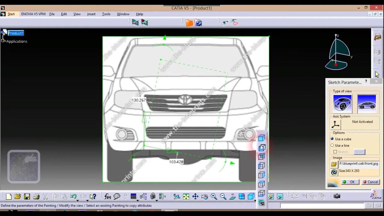
The workspace loads a front-view blueprint of the car with green dashed lines and measurement arrows. The tree structure on the left shows Product1, and the Sketch Parameters dialog on the right displays:
- Type of view: front and side view icons
- Axis System: Not Activated
- Options: Use a cube or line, Stretch (unchecked), Reset button
- Image: Path
F:\blueprint\cab\front.jpg, Size 343 x 293
The blueprint is now loaded and ready for scaling and alignment.
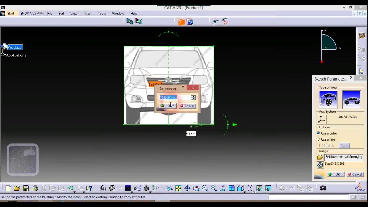
Align and scale the front blueprint
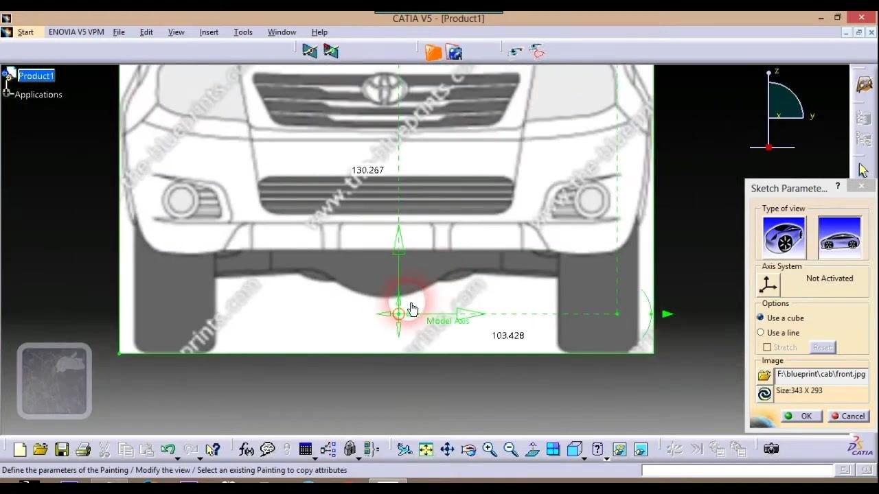
Use the green arrows and handles to adjust the position and scale of the blueprint. The model axis is centered at the bottom of the car's front bumper. The vertical and horizontal green arrows display measurements of 130.267 and 103.428 respectively, and the cursor sits on the model axis to indicate alignment or scaling actions.
Set the blueprint's dimension
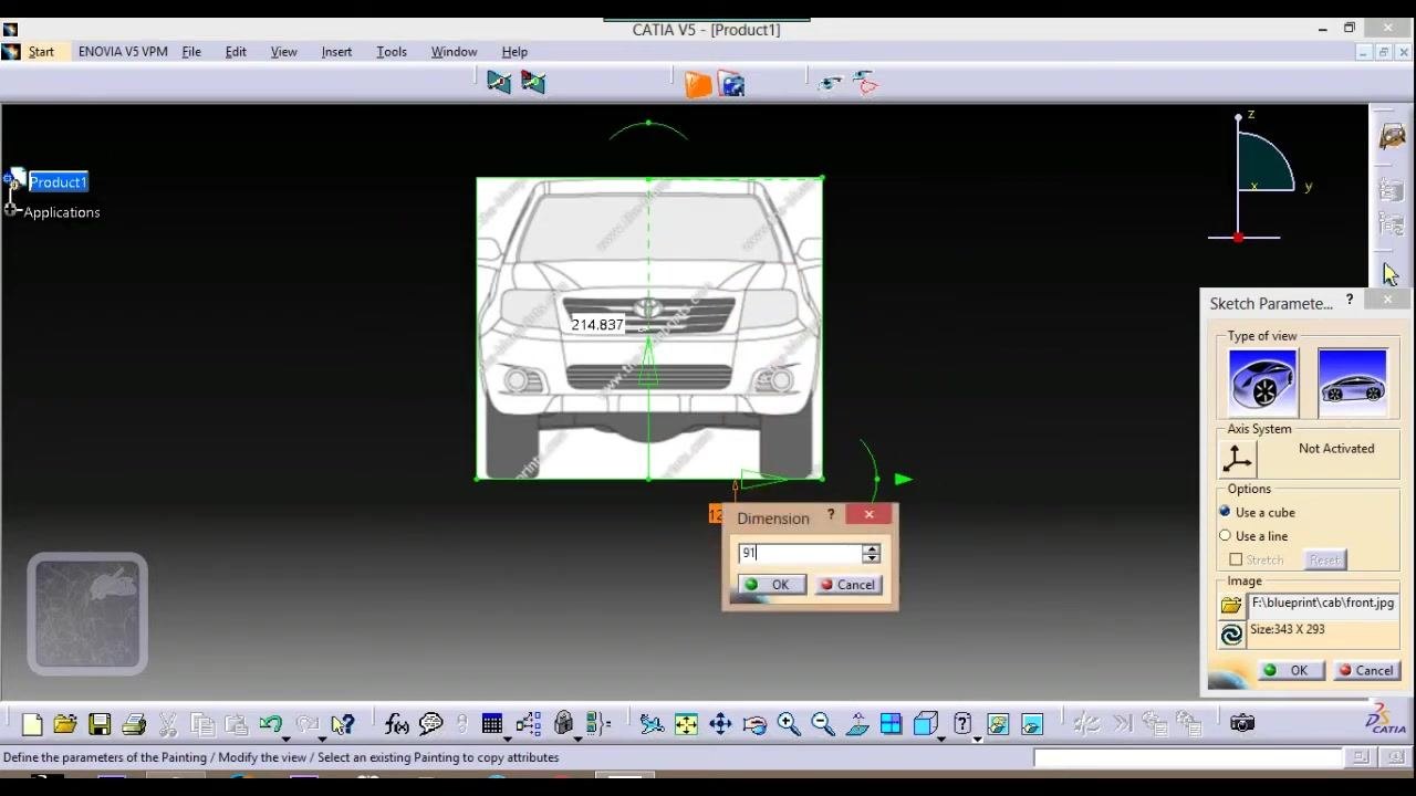
A Dimension dialog box appears, allowing you to enter a specific value. Enter 91 in the input field. The green alignment arrows and handles remain visible around the blueprint, and the vertical measurement updates to 214.837.
Copy the dimension value
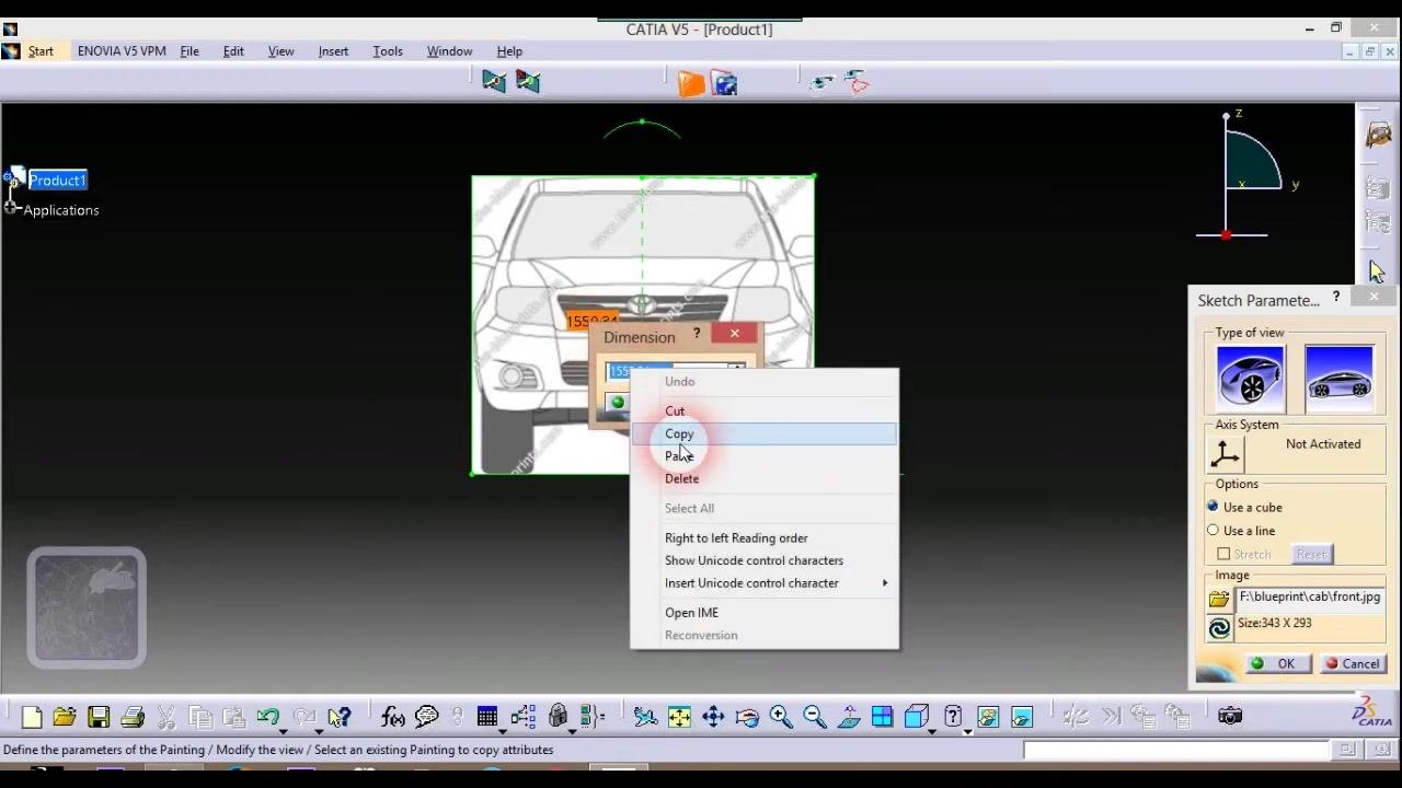
Right-click inside the Dimension dialog box and select Copy from the context menu to copy the dimension value. The dialog shows a dimension value of 1550.34.
Confirm the dimension setting
Click OK in the Dimension dialog to confirm the entered value. The dimension is now set to 1550.34 mm, and the blueprint is scaled accordingly.
With these steps complete, the front blueprint image is imported, aligned, and scaled, ready for further modeling.
Import and align the right-side blueprint
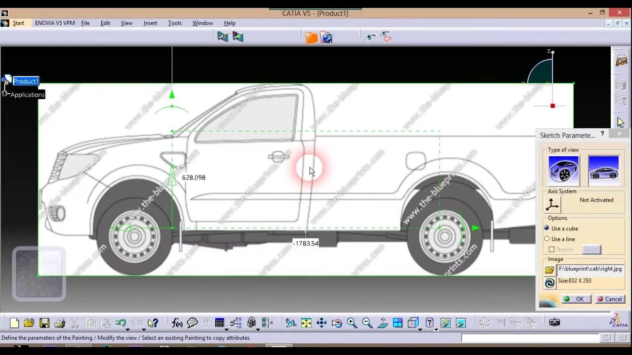
Import the right-side blueprint image
The workspace displays the right-side view of the vehicle loaded as a blueprint. The Sketch Parameters dialog shows:
- Type of view: Side view icon selected
- Axis System: Not Activated
- Options: Use a cube (selected), Use a line, Stretch (unchecked), Reset
- Image: Path
F:\blueprint\cab\right.jpg, Size 832 x 293
Green alignment arrows and handles surround the image, with measurements of 628.098 (vertical) and -1783.54 (horizontal). The cursor is centered on the vehicle, indicating possible alignment or scaling.
Zoom in and adjust alignment handles
Zoom in on the front wheel area of the blueprint. The green alignment arrows and handles remain visible for precise adjustment, with the vertical measurement (628.098) displayed. Position the cursor on the lower-left alignment handle to fine-tune the image position.
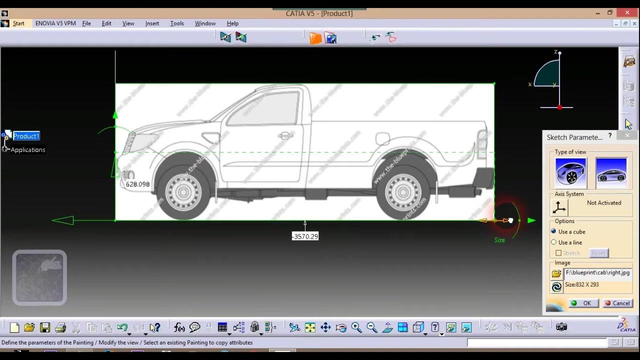
Scale the right-side blueprint
The workspace displays the full right-side blueprint with the green alignment arrows and handles visible. The horizontal measurement updates to -3570.29, and the Sketch Parameters dialog remains open. Position the cursor on the right alignment handle to scale or stretch the image.
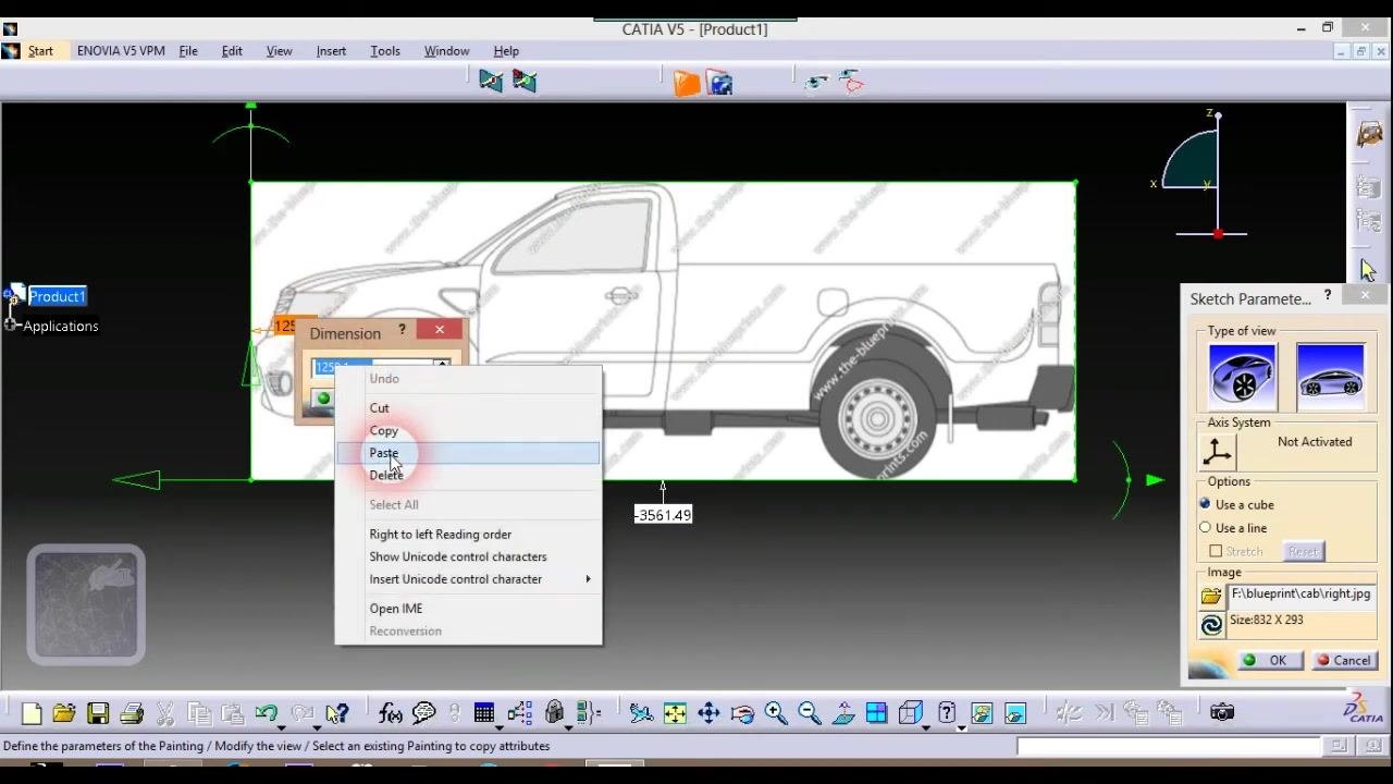
Set the dimension for the right-side blueprint
The Dimension dialog box appears. Enter 1251 mm in the input field. The green alignment arrows and handles remain visible, and the horizontal measurement updates to 3561.49.
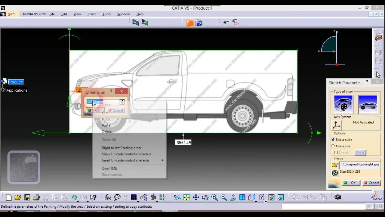
Paste the dimension value
Right-click inside the Dimension dialog box and select Paste from the context menu to apply a copied dimension value. The dialog shows a dimension value of 1251 mm.
Import and align the top blueprint
Import the top blueprint image
The File Selection dialog appears, showing four blueprint images: back, front, right, and top. Select the "top" view image. The file type filter is set to image files (*.tif;*.bmp;*.jpg;*.rgb;*.psd).
Align and scale the top blueprint
The workspace displays the top view of the vehicle as a blueprint. The Sketch Parameters dialog shows:
- Type of view: Top view icon selected
- Axis System: Not Activated
- Options: Use a cube (selected), Use a line, Stretch (unchecked), Reset
- Image: Path
F:\blueprint\cab\top.jpg, Size 828 x 334
Green alignment arrows and handles surround the image, with measurements of -2741.86 (vertical) and 6797.18 (horizontal). The cursor is centered on the vehicle for alignment or scaling.
Zoom in and fine-tune the top view alignment
Zoom in on the front section of the top blueprint. The green alignment arrows and handles remain visible for precise adjustment, with measurements of -3260.63 (vertical) and -8083.25 (horizontal). Position the cursor on the left alignment handle to continue aligning the image.
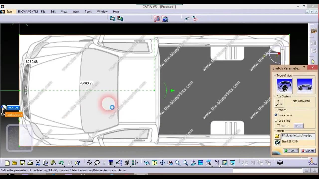
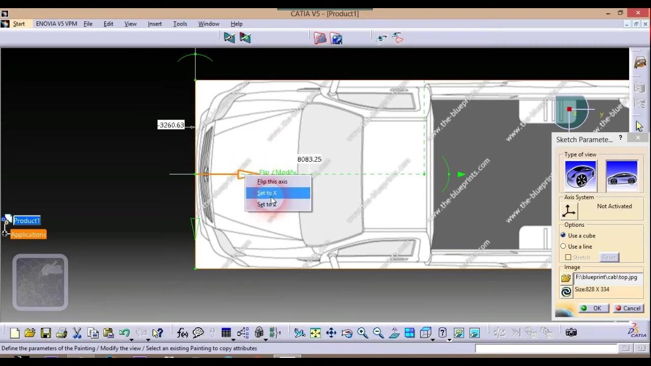
Flip or set the axis for the top blueprint
Right-click on the orange axis handle at the front of the vehicle in the top view. A context menu appears with the options Flip this axis, Set to X, and Set to Z. Select the operation needed to orient the blueprint correctly. The Sketch Parameters dialog remains open, confirming the top view is active, with the image path F:\blueprint\cab\top.jpg (size 828 x 334) and measurements of 3260.63 (vertical) and 8083.25 (horizontal).
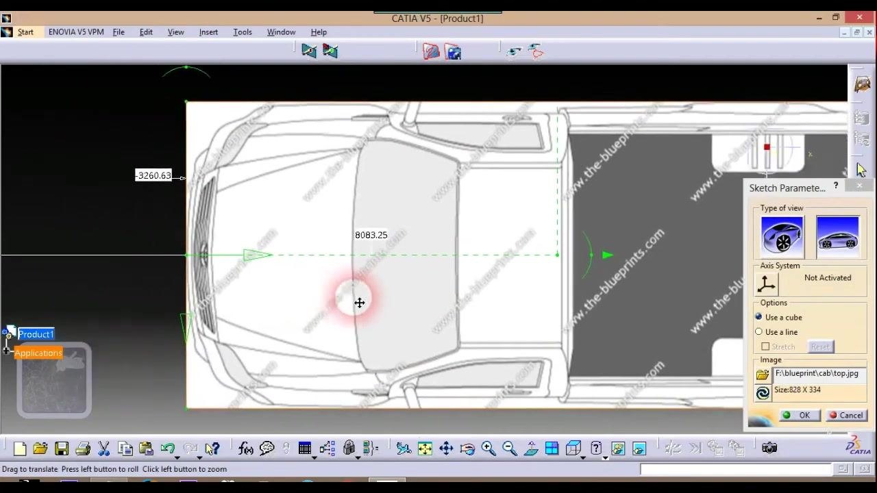
Drag and adjust the top blueprint position
Click and drag the central handle (shown by a crosshair cursor with a red highlight) to reposition the top blueprint image for precise alignment. The workspace displays the top view with green alignment arrows and measurement labels, while the Sketch Parameters dialog stays visible on the right. Make sure the blueprint is centered and aligned with the other views.
Review the combined blueprint views
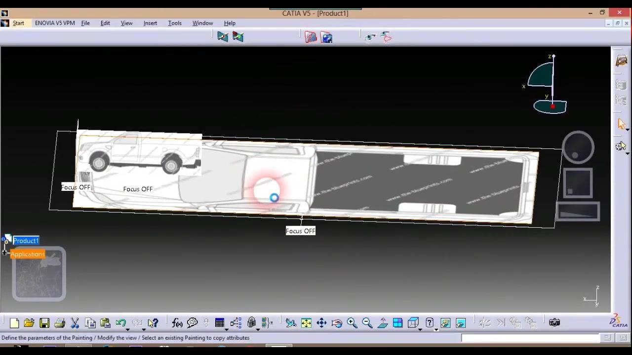
Switch to a 3D perspective to review the alignment of all imported blueprint images. The workspace shows both the side and top blueprints arranged in a 3D box, with "Focus OFF" labels indicating no active selection. Confirm that the blueprints are correctly positioned relative to each other.
Fine-tune the top blueprint alignment
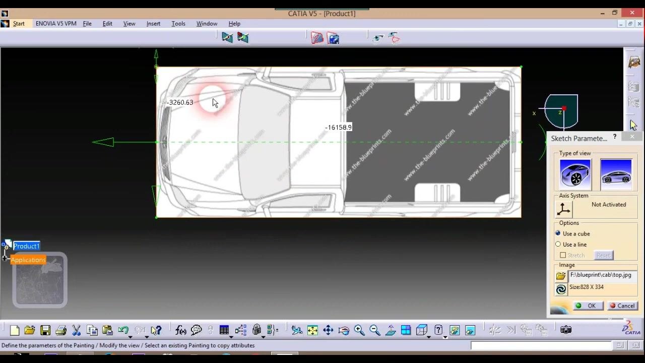
Return to the top view for further adjustment. Click and drag the left alignment handle to adjust the position. The green alignment arrows and updated measurement labels show -3260.63 (vertical) and -16158.9 (horizontal), while the Sketch Parameters dialog remains open.
Set the dimension for the top blueprint
The Dimension dialog box appears in the upper left of the workspace. Enter 917.5 in the input field to set the precise dimension for the top blueprint. The green alignment arrows and measurement labels remain visible, and the Sketch Parameters dialog stays open on the right.
Save your CATIA V5 project
Save the project and choose the save location
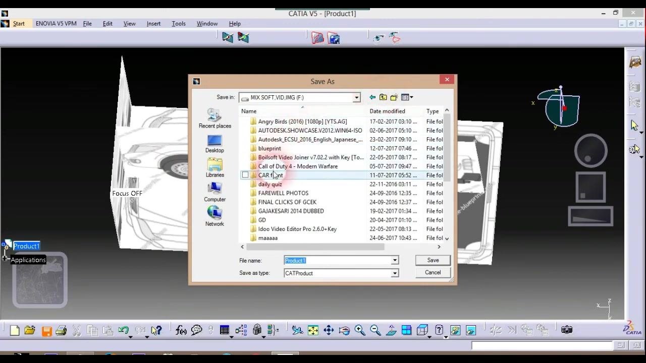
Open the Save As dialog box and navigate to the desired folder (for example, "CAR front"). Select the current product file (Product1) to save your work, with the file type set to CATProduct. If needed, browse to a different directory, such as "MIX_SOFT.VID_IMG (F:)". Confirm the file name and type, then click Save to store your CATIA V5 project.
Verify the saved project and blueprint alignment
After saving, return to the CATIA V5 workspace. The product tree on the left shows Product1 with its parts and planes, and the 3D workspace displays the aligned blueprint images (side and top views) in a box configuration. "Focus OFF" labels indicate no active selection, confirming the project is ready for further 3D modeling.
Confirm the save operation for referenced parts
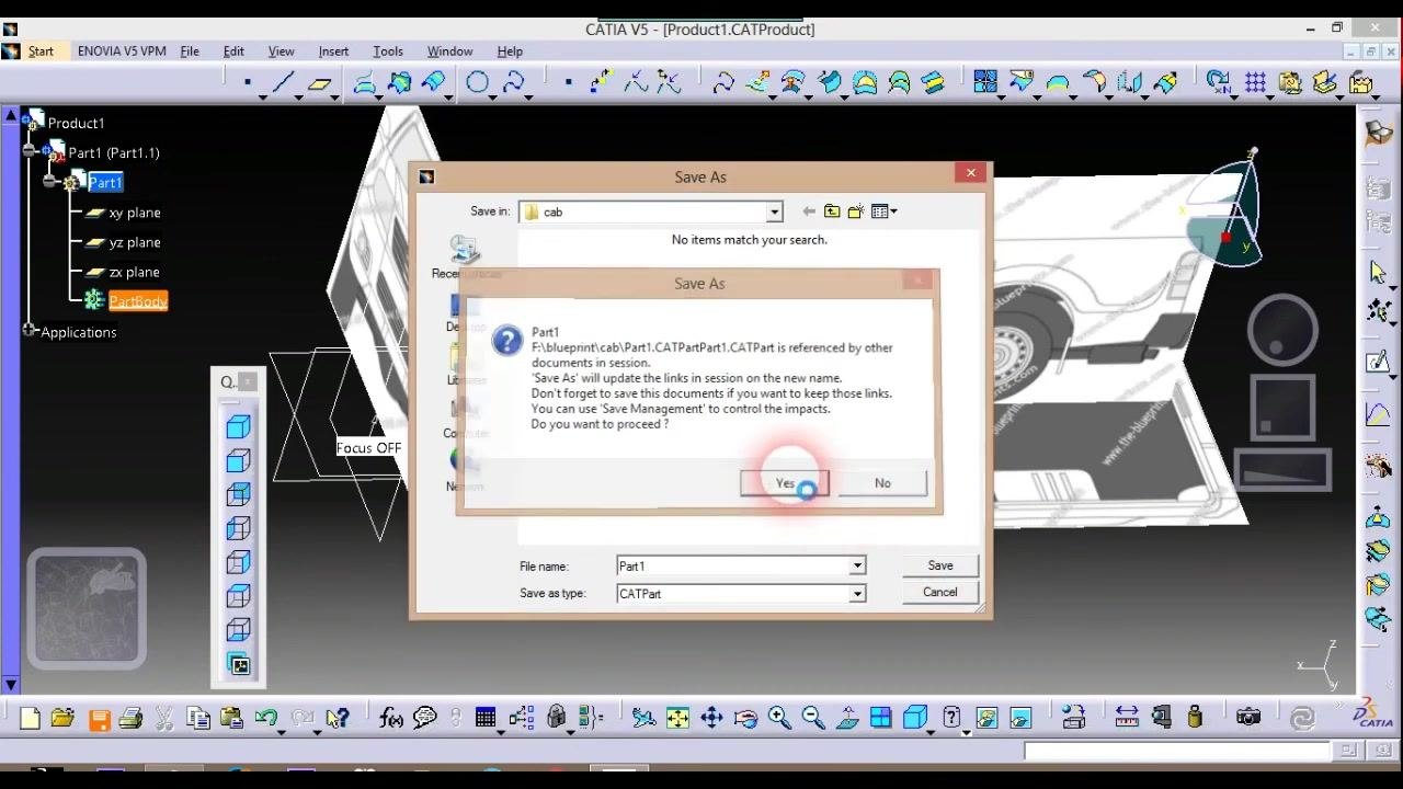
When saving, a Save As dialog appears warning that Part1 is referenced by other documents in the session. It shows the file path F:\blueprint\cab\Part1.CATPart, notes that saving will update links in the session with the new name, reminds you to save all documents to keep those links, and suggests using "Save Management" to control the impact. Click Yes to confirm and proceed with saving the referenced part. The file name is set to Part1 with the file type CATPart.
What's next
With the front, side, and top blueprint images imported, aligned, scaled, and saved, your CATIA V5 project now has a reliable reference framework. You can proceed to build 3D geometry on top of these blueprints as the next stage in designing your car.
Generation details: cost, quality tiers
Docsie billed 3,000 credits ($2.10) to analyze this 6-minute video at standard quality. The rewrite, template fill and Word/PDF exports were included. The same video at each quality tier:
| Quality | Frames sampled | Credits | Approx. cost |
|---|---|---|---|
| Draft | every 16-30 s | 1,500 | $1.05 |
| Standard (this guide) | every 8-15 s | 3,000 | $2.10 |
| Detailed | every 4-7 s | 6,000 | $4.20 |
| Ultra | every 1-3 s | 12,000 | $8.40 |
Credits priced at $0.70 per 1,000; plans include a monthly allowance. Enterprise customers on on-premise or bring-your-own-model deployments run this on their own inference and pay no per-video credits.
Generated by Docsie Video-to-Docs on 2026-10-12 from a 5-minute video. Screenshots are frames from the source video and belong to their creator, HKM Vision3Sixty, whose original is embedded above. If you own this video and want the guide removed or credited differently, contact us and we will act within one business day.