
How to Import Airfoil Coordinates in CATIA
This guide shows you how to import airfoil coordinates in CATIA using a macro-enabled Excel template. You will prepare your coordinate data in Excel, run a macro that transfers the values into CATIA, and generate either points, a spline, or a full loft from the imported data.
Video: How to import Airfoil coordinates from Excel to CATIA V5? by MechStuff (2020). All credit for the demonstration goes to the creator; watch the original on YouTube. The written guide below was generated from this video by Docsie. Creator? Request a change or removal.
This guide shows you how to import airfoil coordinates in CATIA using a macro-enabled Excel template. You will prepare your coordinate data in Excel, run a macro that transfers the values into CATIA, and generate either points, a spline, or a full loft from the imported data.
Prerequisites
Before you begin, make sure you have the following:
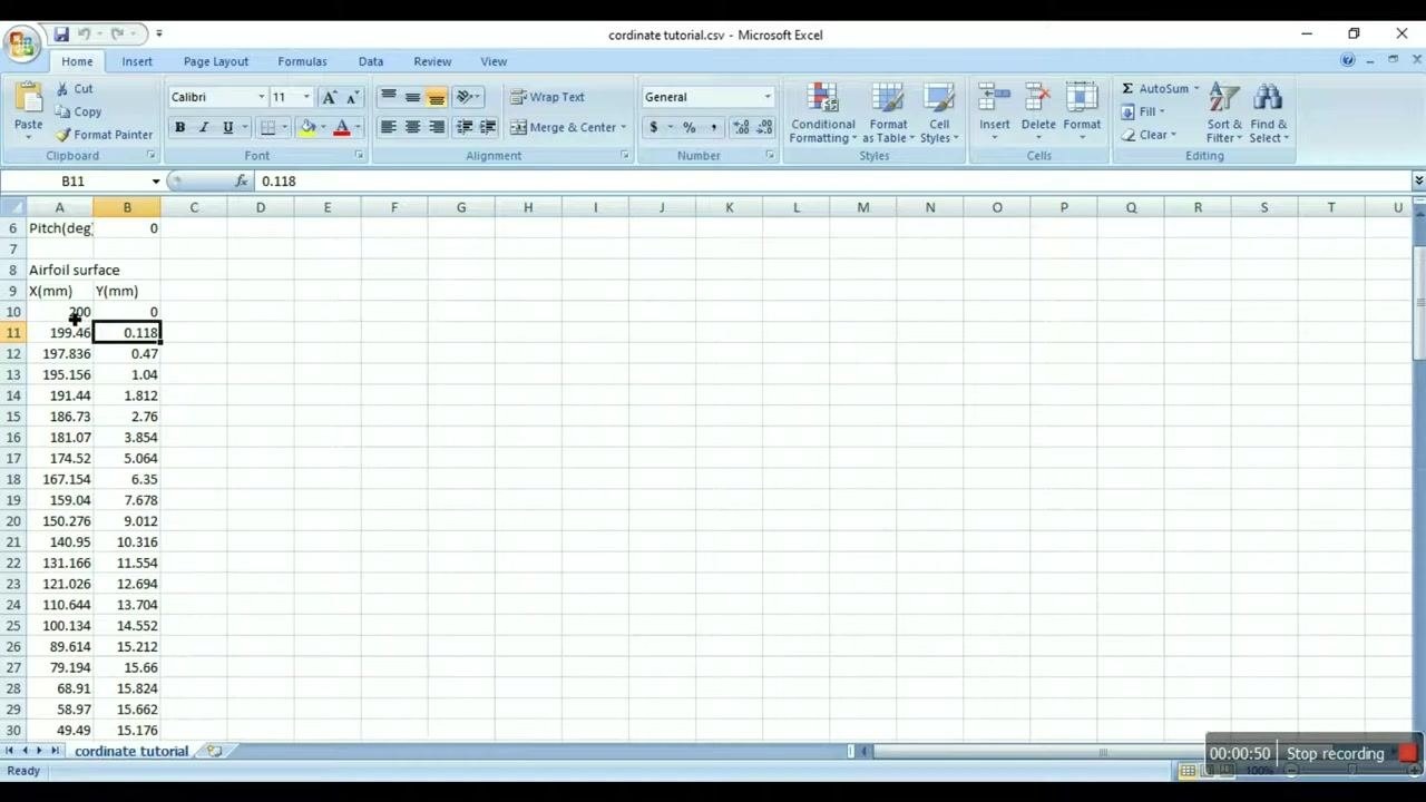
- An Excel file containing your airfoil coordinates in two columns: X (mm) and Y (mm). Example values include X: 200, 199.46, 197.836... and Y: 0, 0.118, 0.47...
- Access to CATIA V5 with the Mechanical Design workbench.
- The
GenerativeShapeDesign_SplineFromExcel.xlstemplate file, available from the website link in the video description.
Confirm that all required coordinate points are present in your source file before moving on.
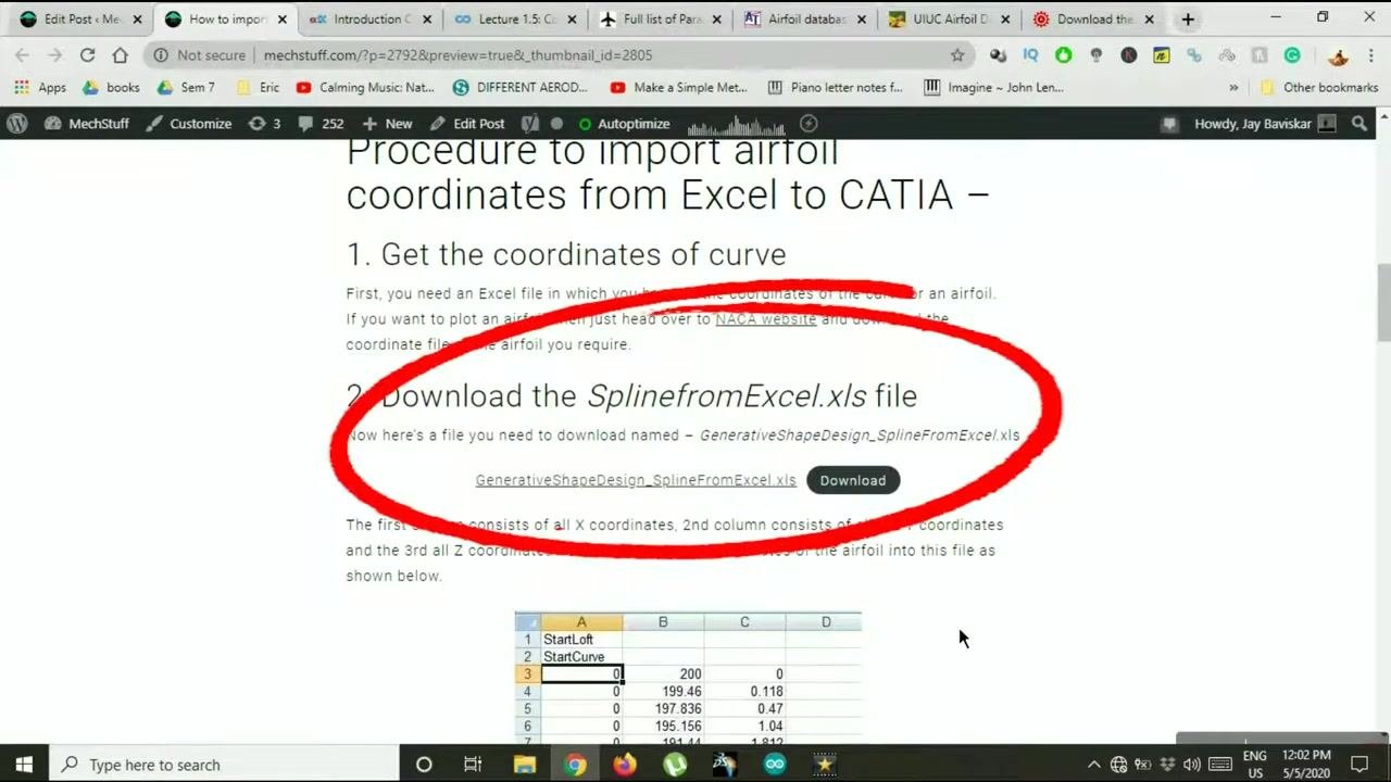
Download the required Excel template
Visit the website link provided and download the file named GenerativeShapeDesign_SplineFromExcel.xls. This template is specifically formatted for importing coordinates into CATIA.
Open the Generative Shape Design spline template
Launch the downloaded GenerativeShapeDesign_SplineFromExcel.xls file in Microsoft Excel. The airfoil will be plotted on the YZ plane in CATIA, so double-check your coordinate orientation to match this requirement before proceeding.
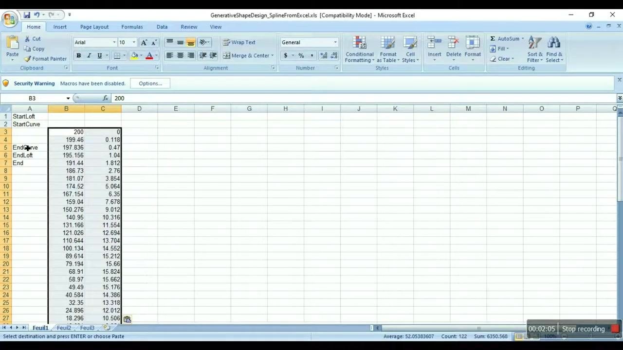
The template expects three columns, structured as follows:
- Column A: X coordinate (to be set as 0)
- Column B: Y coordinate (your original X values)
- Column C: Z coordinate (your original Y values)
Your original X and Y values are treated as Y and Z coordinates in CATIA, and all X coordinates are set to zero.
Copy and paste your airfoil data
Copy the X and Y columns from your original airfoil coordinate file. Paste your original X values into Column B (Y) and your original Y values into Column C (Z) of the template.
Ensure the data is pasted below the StartCurve label and above the EndCurve label.
Set all X coordinates to zero
In Column A (X), enter 0 for each row corresponding to your coordinate points. Use Excel's fill handle to quickly fill down the value 0 for all rows.
Double-check that every X value is zero before continuing.
Enable macros in Excel
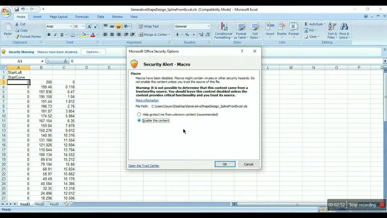
If you see a security warning stating "Macros have been disabled," click Options.... In the Security Alert dialog, select Enable this content, then click OK to allow macros to run in the workbook.
Open CATIA and start a new sketch
Launch CATIA V5. Go to the top menu and select Start > Mechanical Design > Sketcher. When prompted, rename the new part as "airfoil".
Verify the sketch environment
In the CATIA tree, confirm you see the following structure: airfoil, xy plane, yz plane, zx plane, Geometrical Set.1, and PartBody. The main workspace should display the coordinate system.
Run the macro to export data to CATIA
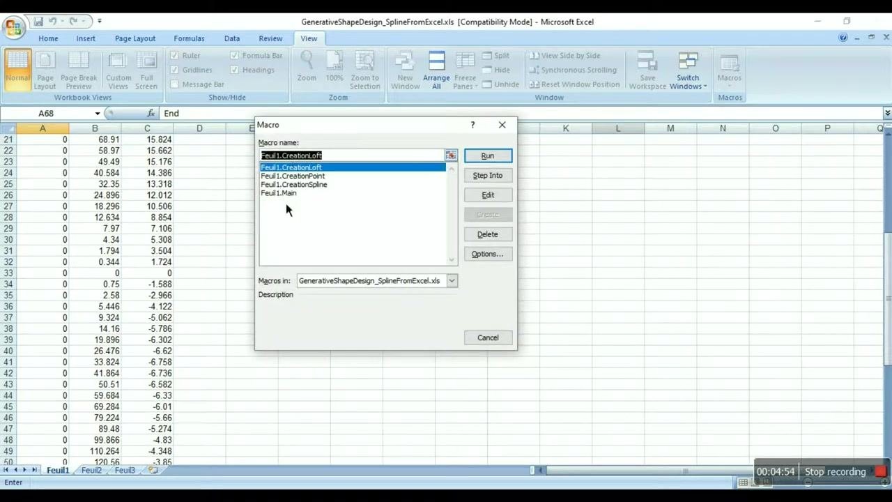
Go to the View tab in Excel. On the right side, click Macros, then select View Macros. In the macro dialog, select Feuil1.Main from the list, confirm it is running from the GenerativeShapeDesign_SplineFromExcel.xls file, and click Run.
Choose the type of entities to create
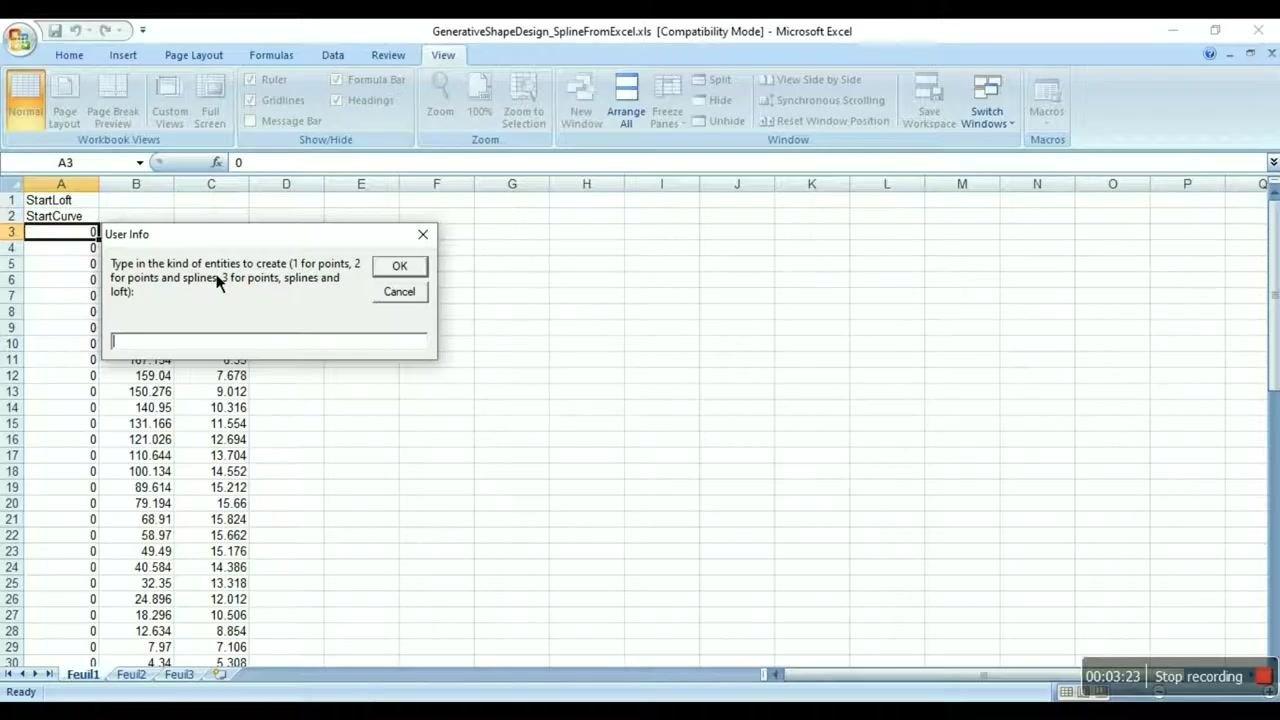
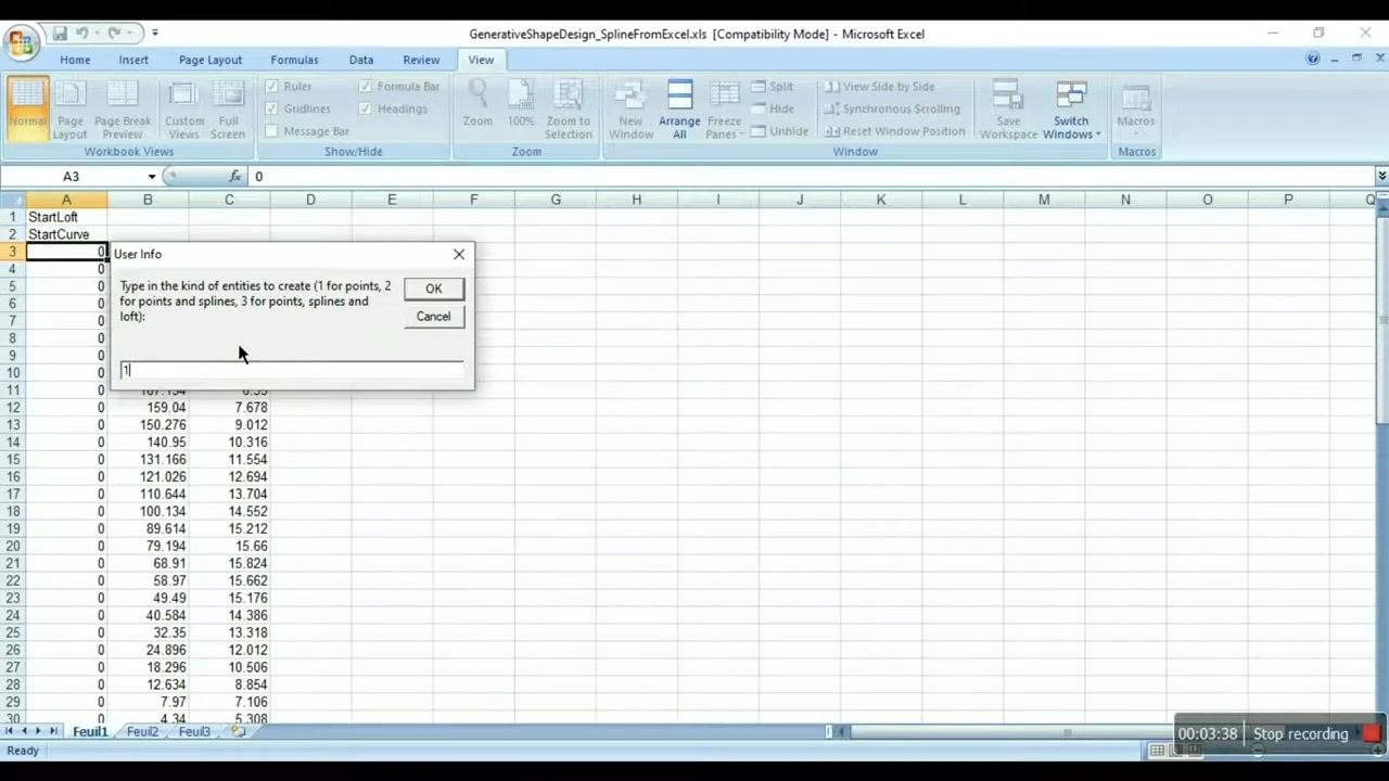
A "User Info" dialog box appears, asking: "Type in the kind of entities to create (1 for points, 2 for points and splines, 3 for points, splines and loft):"
- Enter
1to create only points in CATIA. - Click OK to proceed.
After clicking OK, the macro processes your request. Switch to CATIA to view the imported geometry.
Verify imported points in CATIA
In CATIA, confirm that all airfoil coordinate points have been imported and are visible as individual points on the sketch. The points are listed under GeometryFromExcel in the tree structure, and the airfoil shape is represented by a series of points only.
Delete the imported geometry to try a different option
If you want to try a different import option, select the imported geometry (for example, all points under GeometryFromExcel) in CATIA and delete it to clear the workspace.
Import points and a curve
Return to the Excel macro file and run the macro again by navigating to the View tab, clicking Macros, and selecting Feuil1.Main. When prompted, enter 2 to create both points and a spline (curve), then click OK.
Switch back to CATIA and confirm that both the points and the spline curve representing the airfoil have been imported. The points and the curve appear in the workspace and are listed in the tree structure, giving you a visual airfoil outline in addition to the coordinate points.
Save your work
Save your CATIA project to avoid losing any progress. You can then close CATIA or continue experimenting with additional modeling features.
What's next
With your airfoil points and curve imported, you can continue building on this geometry in CATIA—for example, by using the entity option 3 to generate points, splines, and a loft in a single pass. Keep the source Excel file and template handy if you need to re-import coordinates for a different airfoil profile.
Generation details: cost, quality tiers
Docsie billed 3,000 credits ($2.10) to analyze this 6-minute video at standard quality. The rewrite, template fill and Word/PDF exports were included. The same video at each quality tier:
| Quality | Frames sampled | Credits | Approx. cost |
|---|---|---|---|
| Draft | every 16-30 s | 1,500 | $1.05 |
| Standard (this guide) | every 8-15 s | 3,000 | $2.10 |
| Detailed | every 4-7 s | 6,000 | $4.20 |
| Ultra | every 1-3 s | 12,000 | $8.40 |
Credits priced at $0.70 per 1,000; plans include a monthly allowance. Enterprise customers on on-premise or bring-your-own-model deployments run this on their own inference and pay no per-video credits.
Generated by Docsie Video-to-Docs on 2026-10-14 from a 5-minute video. Screenshots are frames from the source video and belong to their creator, MechStuff, whose original is embedded above. If you own this video and want the guide removed or credited differently, contact us and we will act within one business day.