
How to Make an Animation in CATIA
This guide shows you how to make an animation in CATIA V5 by building a simple crank mechanism and animating it to rotate from 0 to 360 degrees. You will create the individual parts, assemble them with constraints, convert the assembly into a kinematic mechanism, and compile a playable simulation of the crank's rotation.
Video: Animation in CATIA v5 ?? #animationCATIA #catia by The Nor Design (2013). All credit for the demonstration goes to the creator; watch the original on YouTube. The written guide below was generated from this video by Docsie. Creator? Request a change or removal.
This guide shows you how to make an animation in CATIA V5 by building a simple crank mechanism and animating it to rotate from 0 to 360 degrees. You will create the individual parts, assemble them with constraints, convert the assembly into a kinematic mechanism, and compile a playable simulation of the crank's rotation.
Prerequisites
- CATIA V5 installed and ready to launch.
- Basic familiarity with the CATIA Part Design and Assembly Design workbenches.
Setting up the product structure
Open CATIA V5 and prepare the product structure
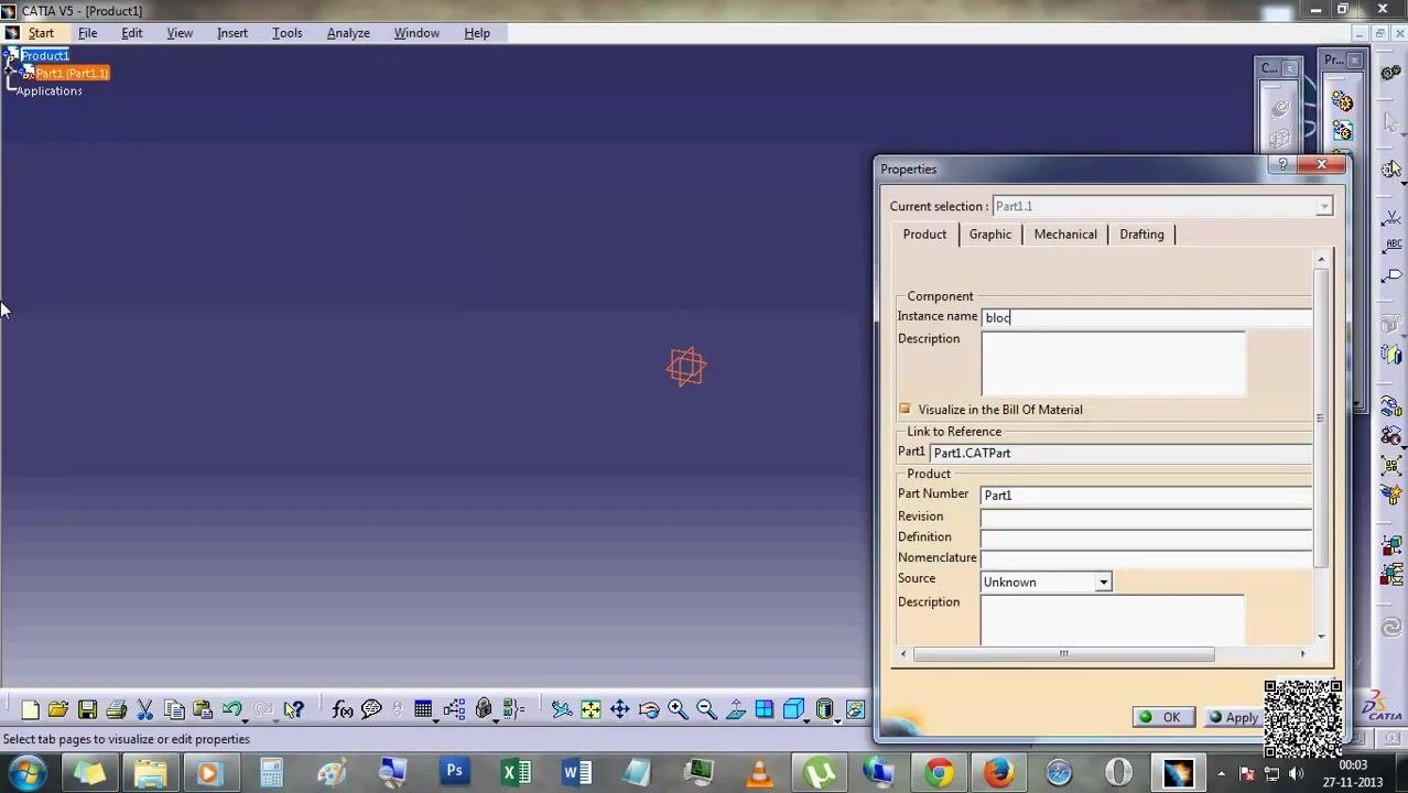
Launch CATIA V5. You see a workspace titled CATIA V5 - [Product1], with a product tree on the left showing Product1 containing Part1 (Part1.1).
Open the Properties dialog for Part1.1. In the Component section, set Instance name to block. Make sure Visualize in the Bill Of Material is checked. The Product section shows Part Number: Part1.
Insert an existing component
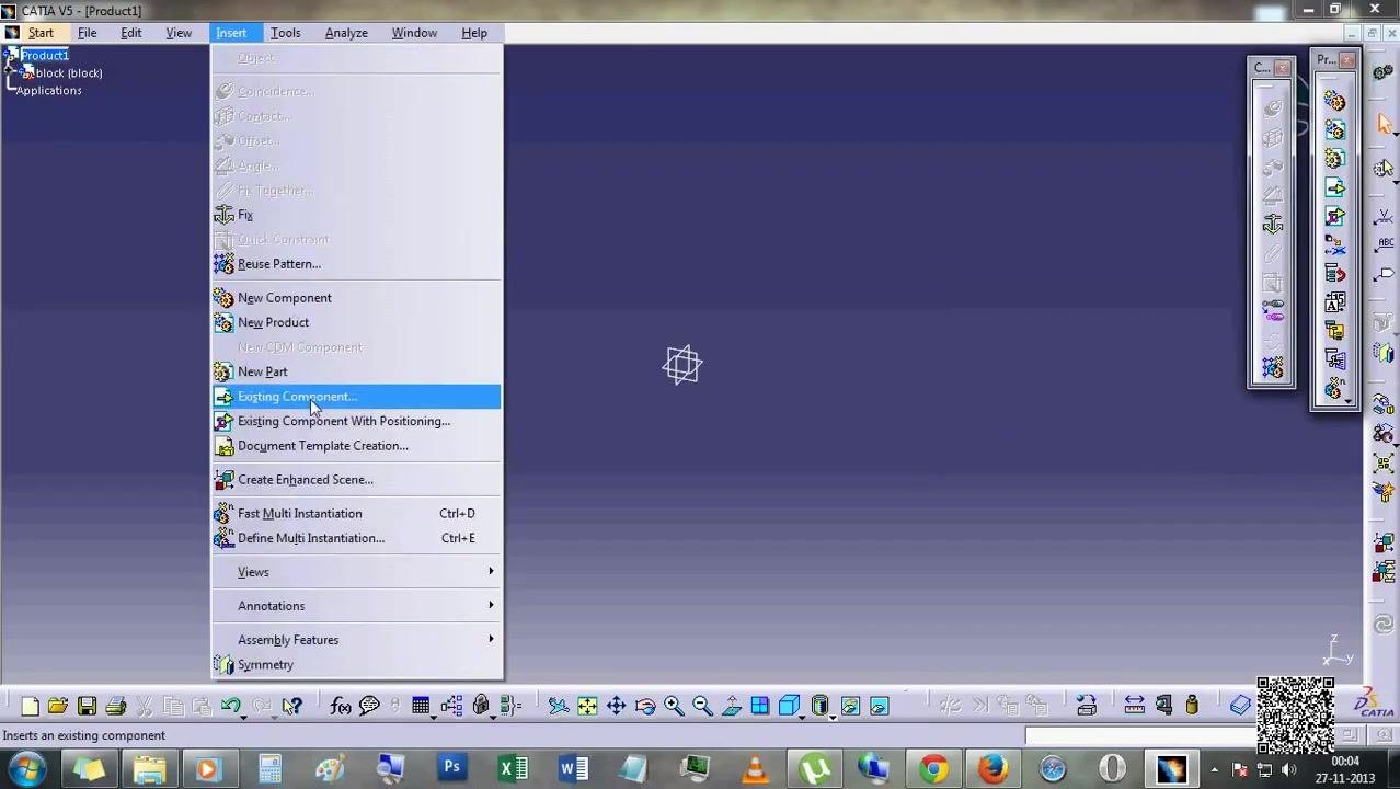
In the menu bar, click Insert, then select Existing Component... from the dropdown. This adds another part to the product structure.
The product tree now shows block (block) under Product1.
Set properties for the new component
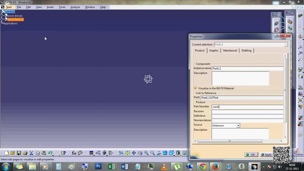
The Properties dialog opens automatically for the newly inserted component, Part1.2. In the Product section, set Part Number to crank.
The product tree now lists both block (block) and Part1 (Part1.2) under Product1.
Building the block and crank
Sketch the block
Enter the sketching environment for the block part. Use the rectangle tool to draw a square on the grid, positioned at the origin where the X and Y axes intersect.
The rectangle's dimensions appear as: Second Point H = 90 mm, V = -100 mm, Width = 90 mm. The Sketch tools toolbar is visible at the top of the workspace.
Pad the sketch into a 3D block
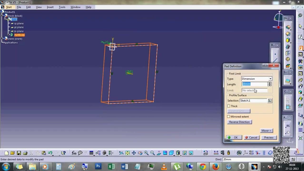
Exit the sketch and open the Pad Definition dialog. Set First Limit type to Dimension and enter Length = 20mm. Confirm Profile/Surface is set to Sketch.1.
Click OK to create a 3D block from the rectangle.
Sketch the crank
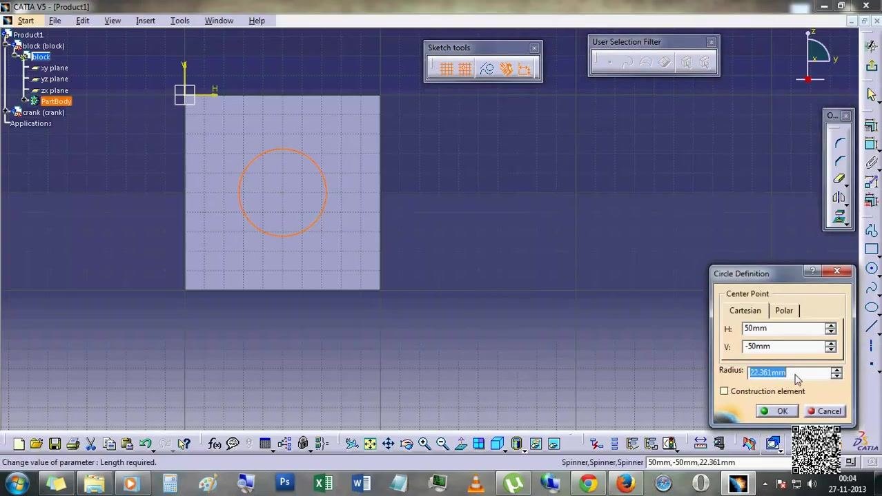
Enter the sketching environment for the crank part and draw a circle on the grid. In the Circle Definition dialog, set Center Point to H = 50 mm, V = -50 mm, with an initial Radius of 22.361 mm.
Adjust the circle radius
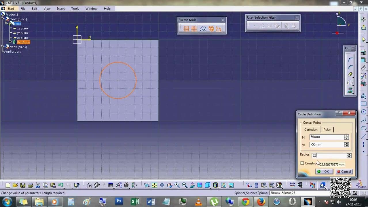
In the Circle Definition dialog, change the radius value to 25mm and click OK to confirm.
The circle updates to reflect the new radius.
Visualize the assembled block and crank
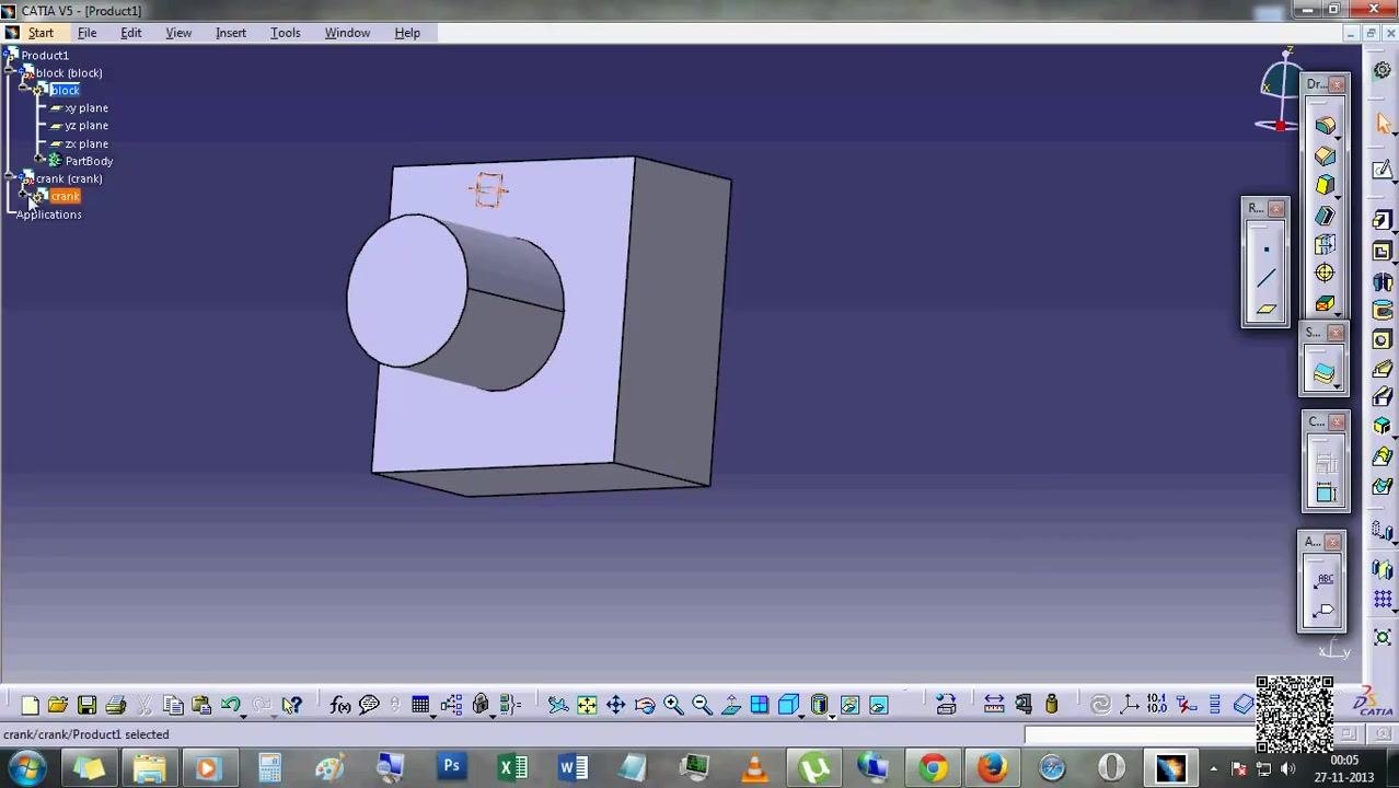
Exit the sketching environment. The 3D view now shows a block with a cylindrical crank protruding from its face, and the product tree lists both block and crank under Product1.
Sketching the crank arm
Begin the crank arm sketch
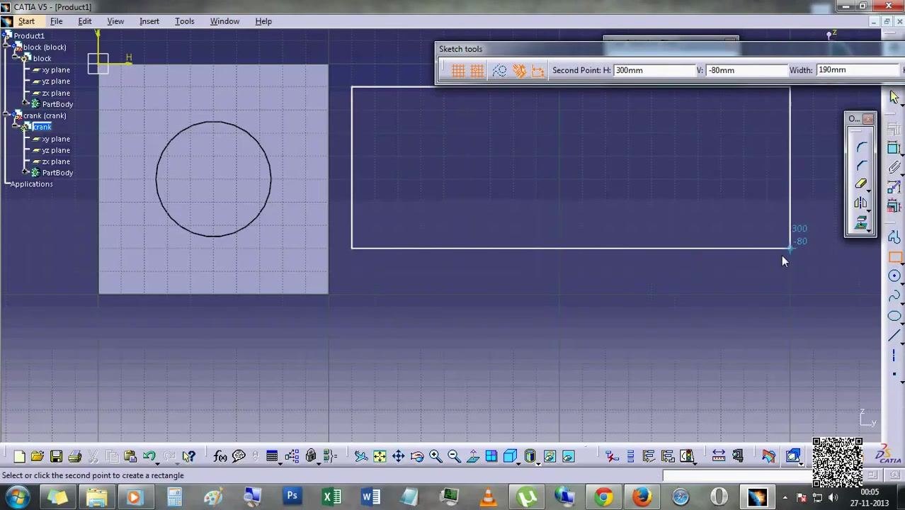
Enter the sketching environment for the crank part again. Draw a large rectangle on the grid, starting from the left of the circle.
The rectangle's dimensions appear as: Second Point H = 300 mm, V = -80 mm, Width = 190 mm.
Add circles to the crank arm sketch
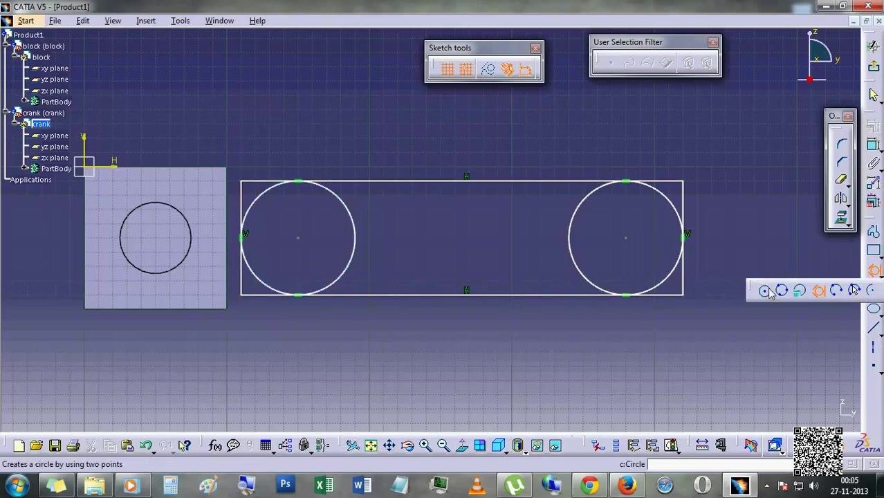
With the large rectangle (crank arm) and the previously drawn circle at the left end in view, draw two additional circles, one at each end of the rectangle. Position them tangent or nearly tangent to the rectangle's shorter sides.
These circles form the basis for the holes or pivots in the crank arm.
Add an inner circle for the pivot hole
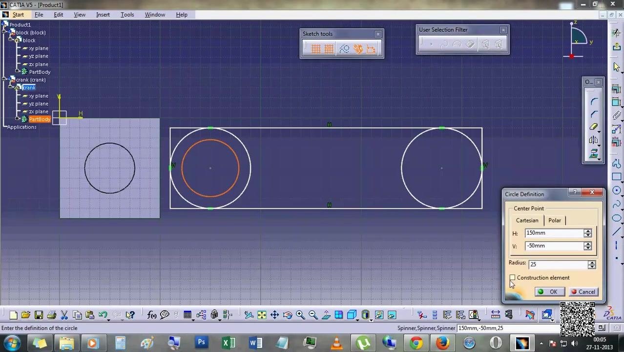
Draw an inner circle concentric with the leftmost large circle. In the Circle Definition dialog, set Center Point to H = 150 mm, V = -50 mm, with Radius = 25mm.
Make sure Construction element is unchecked so the circle becomes a solid feature, then click OK.
Finalize the crank arm sketch
Confirm the sketch now contains a large rectangle (the crank arm body), two large circles at each end, and an inner circle at the left end (the pivot hole). Exit the sketching environment to proceed with 3D operations.
Pad and assemble the crank arm
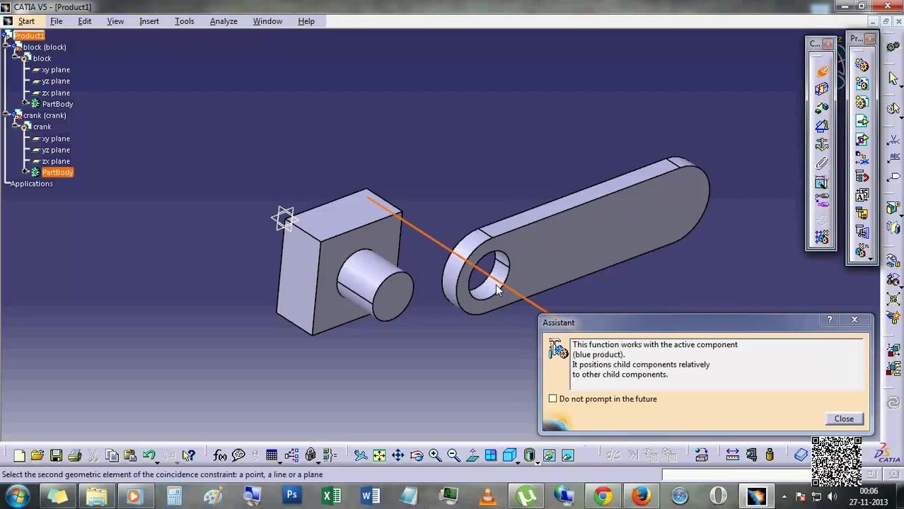
Use the Pad feature to extrude the crank arm sketch into a 3D solid. The 3D view now shows the block and the crank arm as separate solid bodies, with the crank arm displaying rounded ends and a hole at the left end that matches the block's cylindrical protrusion.
Assembling the parts
Position the crank arm
Use the Manipulation panel to drag the crank arm along the Z axis or rotate it as needed for alignment. The crank arm is highlighted in orange to indicate it is the active component being positioned.
Make sure the crank arm's hole aligns with the block's protrusion.
Apply a coincidence constraint
Enter the Assembly Design workbench. Select the cylindrical face of the block's protrusion and the inner cylindrical face of the crank arm's hole, then apply a Coincidence constraint to align the two faces.
An Assistant dialog explains: "This function works with the active component (blue product). It positions child components relatively to other child components." Click Close to dismiss it.
Set coincidence constraint properties
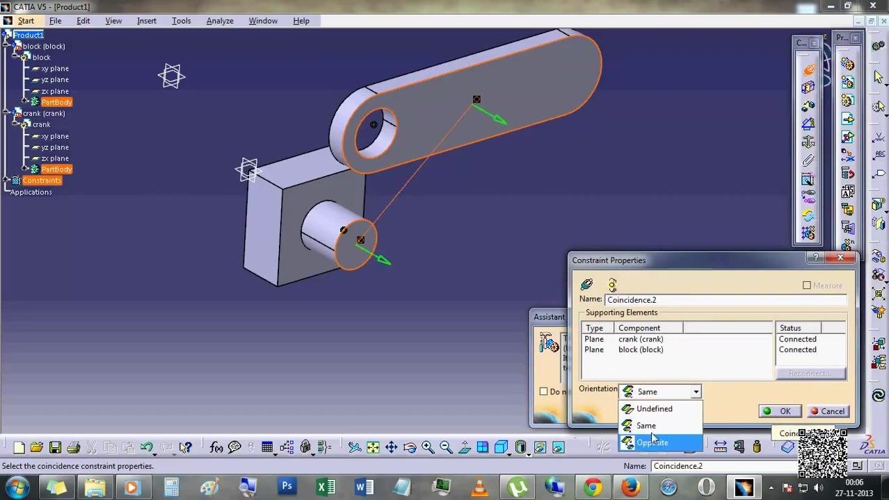
The Constraint Properties dialog appears for Coincidence.2, showing Supporting Elements of type Component, with Plane: crank (crank) and block (block), and Status: Connected.
Set Orientation to Opposite if needed for correct alignment, then click OK to apply the constraint.
Verify the assembly and fix the block
Confirm the crank arm is now assembled onto the block, with its hole fitting over the block's cylindrical protrusion. In the constraints tree, verify:
- Coincidence.1 (crank, block)
- Coincidence.2 (crank, block)
- Fix.3 (block) — fixes the block in space to prevent movement
The assembly is now ready for animation.
Setting up DMU kinematics
Switch to the DMU Kinematics workbench
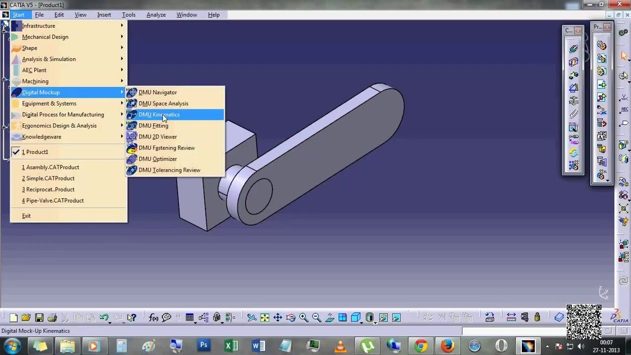
Open the Start menu from the top left and navigate to Digital Mockup > DMU Kinematics. Select DMU Kinematics to enter the kinematic simulation environment.
Start the assembly constraints conversion
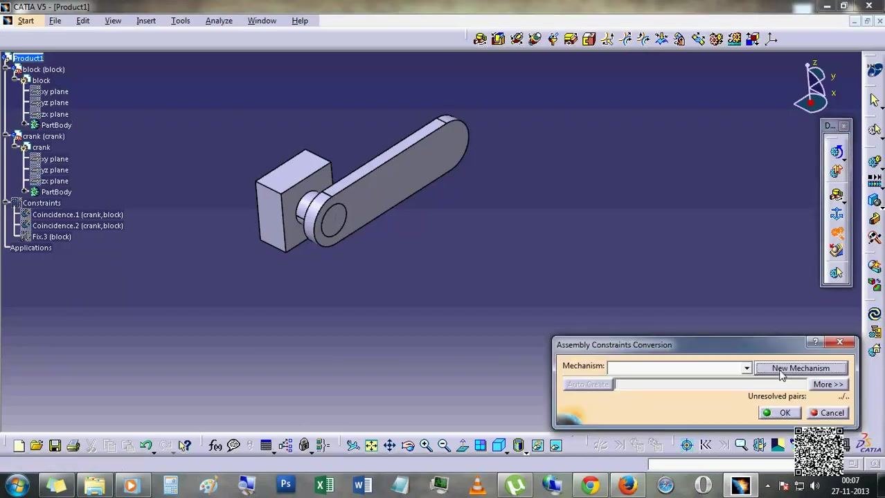
The workspace displays the assembly with the Assembly Constraints Conversion dialog open at the bottom right. In the dialog, the Mechanism dropdown is set to New Mechanism, and the dialog is ready for mechanism creation.
Create and name the mechanism
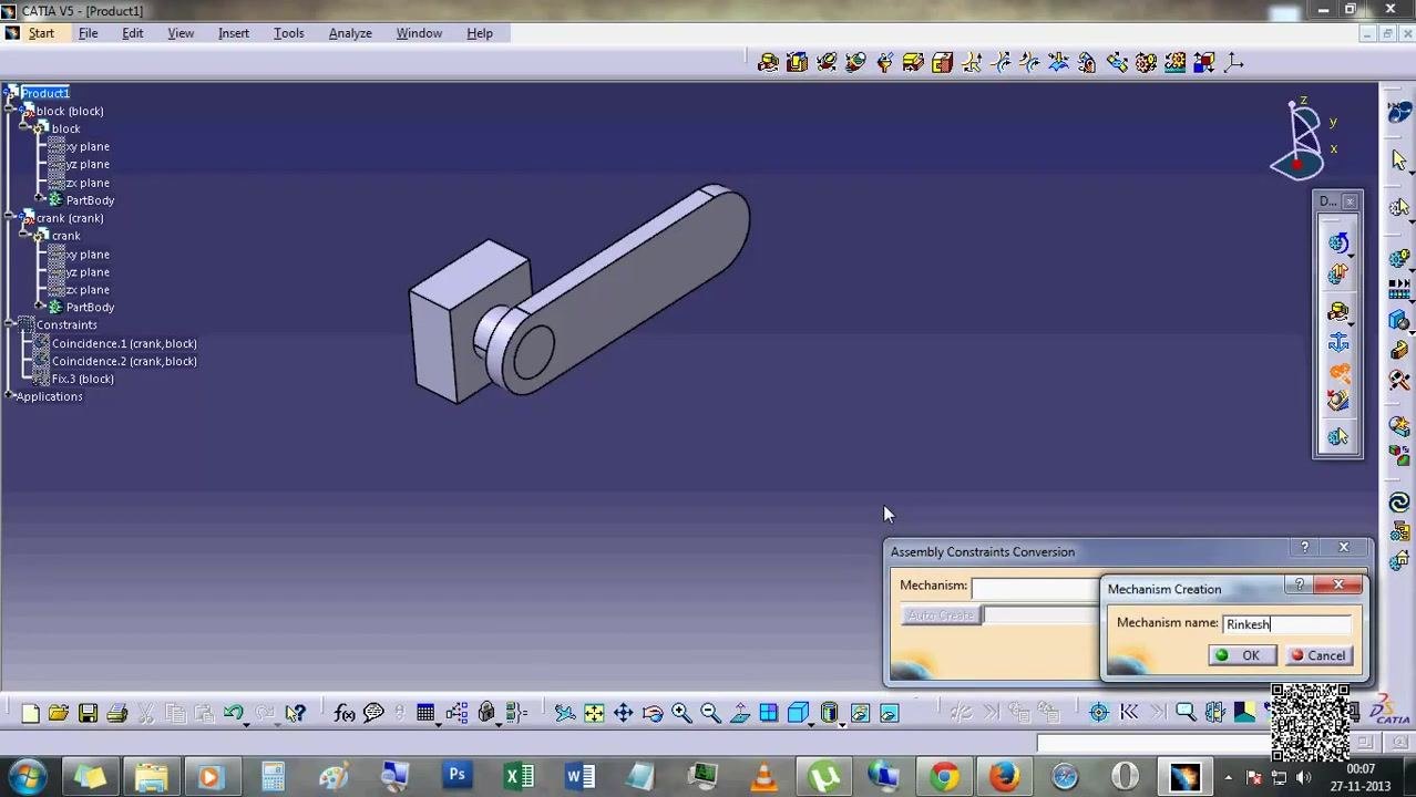
In the Assembly Constraints Conversion dialog, click to create a new mechanism. A Mechanism Creation dialog appears, prompting you for a name.
Enter the desired mechanism name and click OK to confirm. The name then appears in the dialog.
Verify mechanism creation
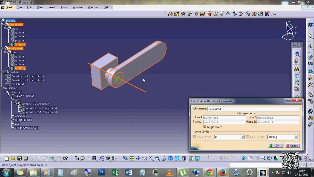
Check that the mechanism is now listed under Applications in the tree on the left, for example as "DOF=1" (Degree of Freedom = 1). The mechanism contains joints (such as Revolute.1 (crank, block)), commands, a fixed part (block), and any laws or speeds-accelerations.
The assembly remains unchanged visually, confirming successful mechanism creation.
Edit the revolute joint properties
In the Joint Edition: Revolute.1 dialog, set the joint geometry: Line 1: crank/Pad.1, Line 2: block/Solid.1, Plane 1: crank/Pad.1, Plane 2: block/Solid.1.
Check Angle driven to control the rotation, and set joint limits to Lower limit: 0° and Upper limit: 360°. Click OK to confirm.
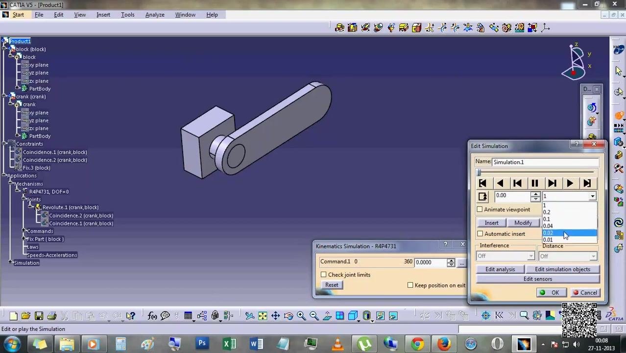
Open the kinematics simulation settings
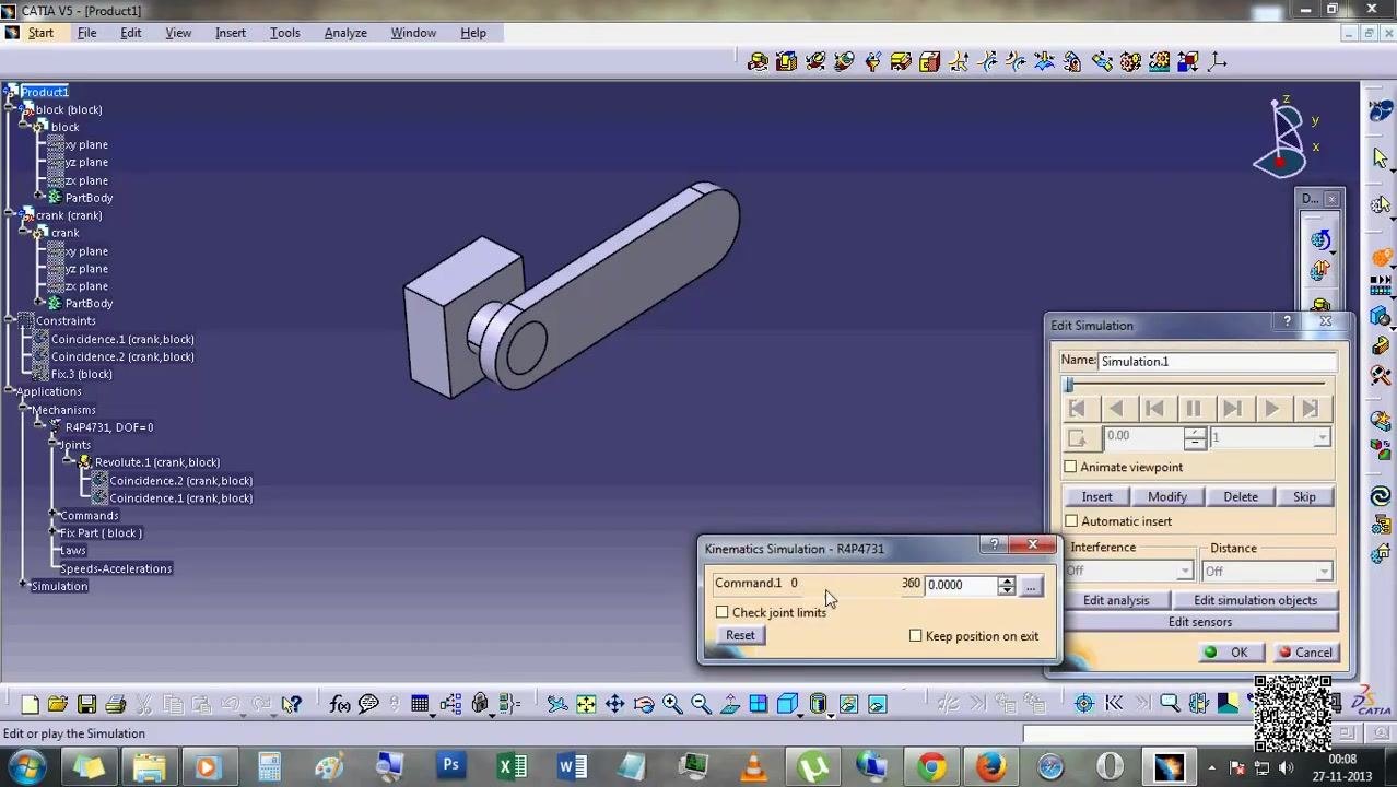
The Kinematics Simulation dialog appears, showing Command.1 ranging from 0 to 360, with an option to check joint limits and reset.
The Edit Simulation dialog also opens, letting you name the simulation (for example, "Simulation.1"), use playback controls, insert or modify steps, enable Automatic insert, and set interference checking.
Set the simulation step size
In the Edit Simulation dialog, use the dropdown to select a step size value (for example, 0.02). This determines the increment for each simulation step.
Make sure Automatic insert is checked if you want steps added automatically.
Compiling and playing the simulation
Compile the simulation
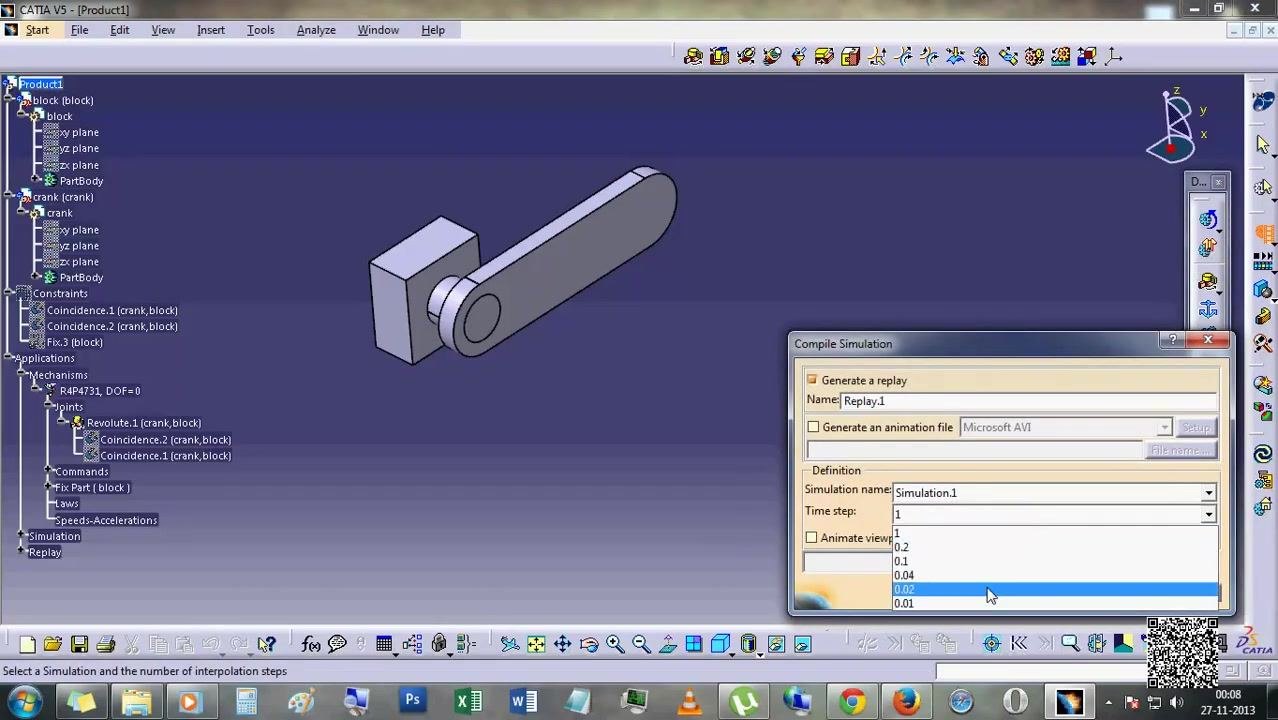
In the Compile Simulation dialog, check Generate a replay and enter the replay name as Replay.1. Optionally, check Generate an animation file and select a format (such as Microsoft AVI) if you want to export the animation.
Under Definition, confirm Simulation name is set to Simulation.1, and set the Time step value (for example, 0.02). Optionally, check Animate viewpoint if you want the camera to move during the simulation.
Play the simulation replay
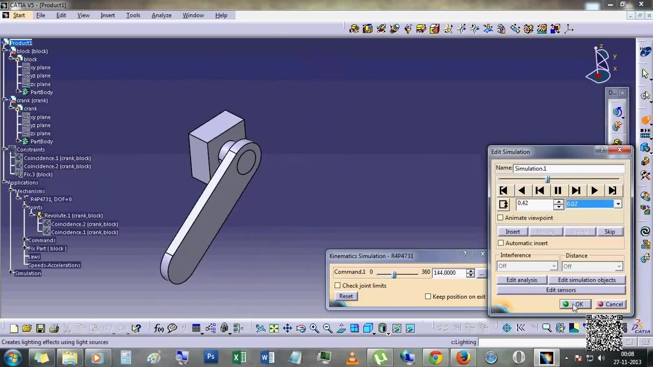
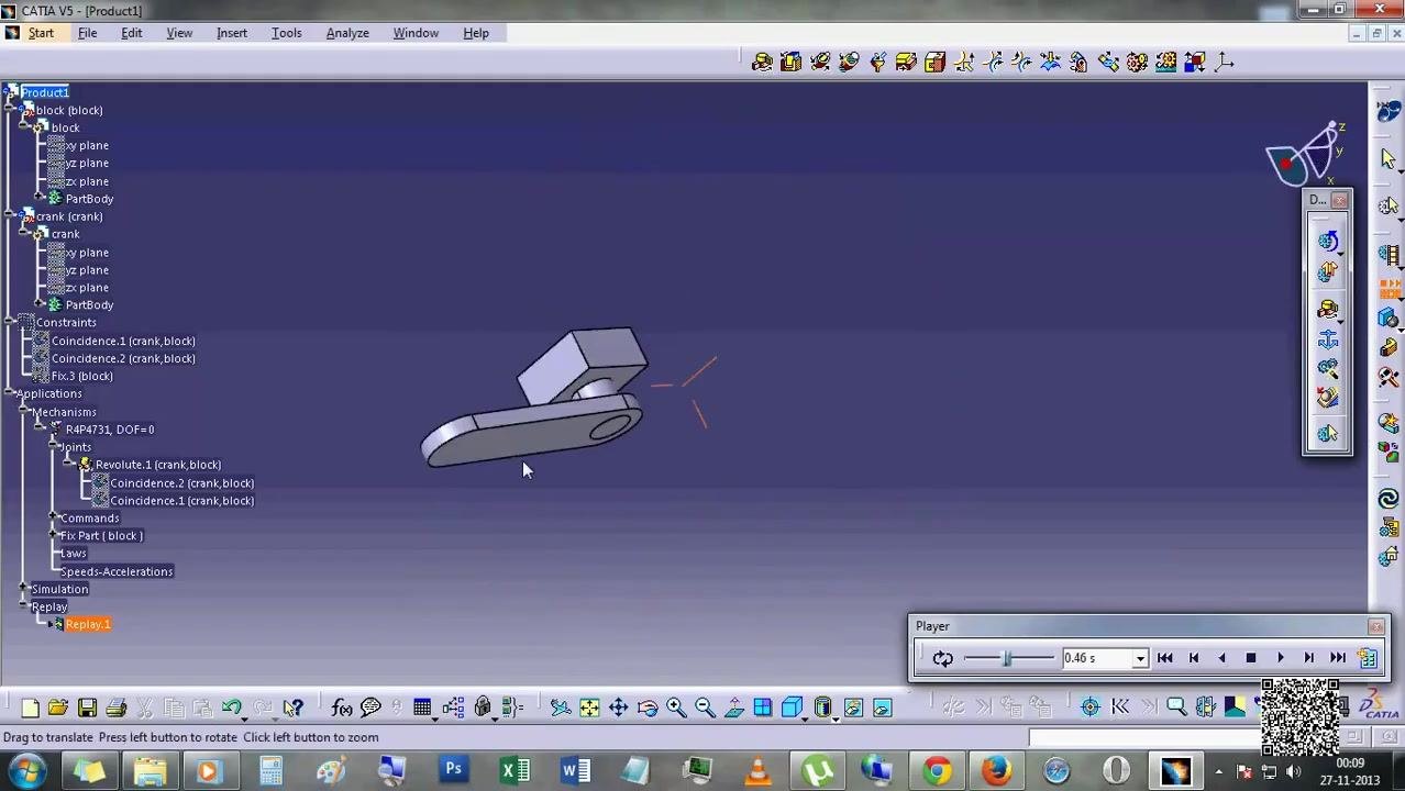
Once the simulation is compiled, a Player window appears at the bottom right, and the assembly is shown in the main workspace, ready for replay. The replay (Replay.1) is now listed under the Simulation section in the tree.
Use the player controls to start the replay and observe the mechanism's motion.
Interact with the simulation view
Rotate, zoom, or pan the 3D view during or after the simulation to inspect the mechanism from different angles. The simulation continues to play, showing the full range of motion defined by the constraints and commands.
The Player window displays the current simulation time, for example 0.46s.
Summary
You have now learned how to make an animation in CATIA V5 by building a block and crank, assembling them with coincidence constraints, converting the assembly into a kinematic mechanism with a revolute joint driven from 0 to 360 degrees, and compiling a replay to visualize the crank's rotation.
Generation details: cost, quality tiers
Docsie billed 3,500 credits ($2.45) to analyze this 7-minute video at standard quality. The rewrite, template fill and Word/PDF exports were included. The same video at each quality tier:
| Quality | Frames sampled | Credits | Approx. cost |
|---|---|---|---|
| Draft | every 16-30 s | 1,750 | $1.22 |
| Standard (this guide) | every 8-15 s | 3,500 | $2.45 |
| Detailed | every 4-7 s | 7,000 | $4.90 |
| Ultra | every 1-3 s | 14,000 | $9.80 |
Credits priced at $0.70 per 1,000; plans include a monthly allowance. Enterprise customers on on-premise or bring-your-own-model deployments run this on their own inference and pay no per-video credits.
Generated by Docsie Video-to-Docs on 2026-10-14 from a 6-minute video. Screenshots are frames from the source video and belong to their creator, The Nor Design, whose original is embedded above. If you own this video and want the guide removed or credited differently, contact us and we will act within one business day.