
How to Write G Code for a CNC Machine
This guide shows you how to write G-code for a CNC machine to build a tool counting macro that tracks tool life, faults out automatically when a tool reaches its limit, and prompts the operator with a clear message. A macro is an automated input sequence that imitates keystrokes or mouse actions, and macro variables can significantly increase efficiency in CNC machining. Mastering macros can elevate your programming skills, since they can automate tasks such as tool counting, tool life management, and resetting messages, allowing an operator to press start and let the macro handle the rest. Because each CNC machine handles tool counters and menus differently, a custom macro is often the most reliable solution.
Video: Secret Art of MACRO PROGRAMMING on a CNC Machine | G-Code Genius by TITANS of CNC MACHINING (2023). All credit for the demonstration goes to the creator; watch the original on YouTube. The written guide below was generated from this video by Docsie. Creator? Request a change or removal.
This guide shows you how to write G-code for a CNC machine to build a tool counting macro that tracks tool life, faults out automatically when a tool reaches its limit, and prompts the operator with a clear message. A macro is an automated input sequence that imitates keystrokes or mouse actions, and macro variables can significantly increase efficiency in CNC machining. Mastering macros can elevate your programming skills, since they can automate tasks such as tool counting, tool life management, and resetting messages, allowing an operator to press start and let the macro handle the rest. Because each CNC machine handles tool counters and menus differently, a custom macro is often the most reliable solution.

Purpose
This document explains how to write, test, and apply a G-code macro that counts tool cycles, checks tool life against a maximum value, and stops the program safely with an operator message when the tool needs to be changed.
Scope
This procedure covers writing macro variables into an existing CNC program, adding conditional (IF) logic, using GOTO statements to control program flow, displaying operator messages, resetting the tool counter, and performing the physical insert change once the macro fault triggers.

Prerequisites and required equipment
- Access to a CNC control panel with macro programming capability (demonstrated on a FANUC Series 31i-MODEL B Plus control).
- An existing CNC program with a defined tool path and cutoff operation.
- Familiarity with your machine's offset and macro variable screens.
-
A reference copy of FANUC CNC Custom Macros by Peter Smid is recommended, as it covers programming resources for custom macro users at both beginner and advanced levels.
-
Safety glasses (required before handling tool holders or inserts).
- A replacement insert and the appropriate tool for removing and installing it.
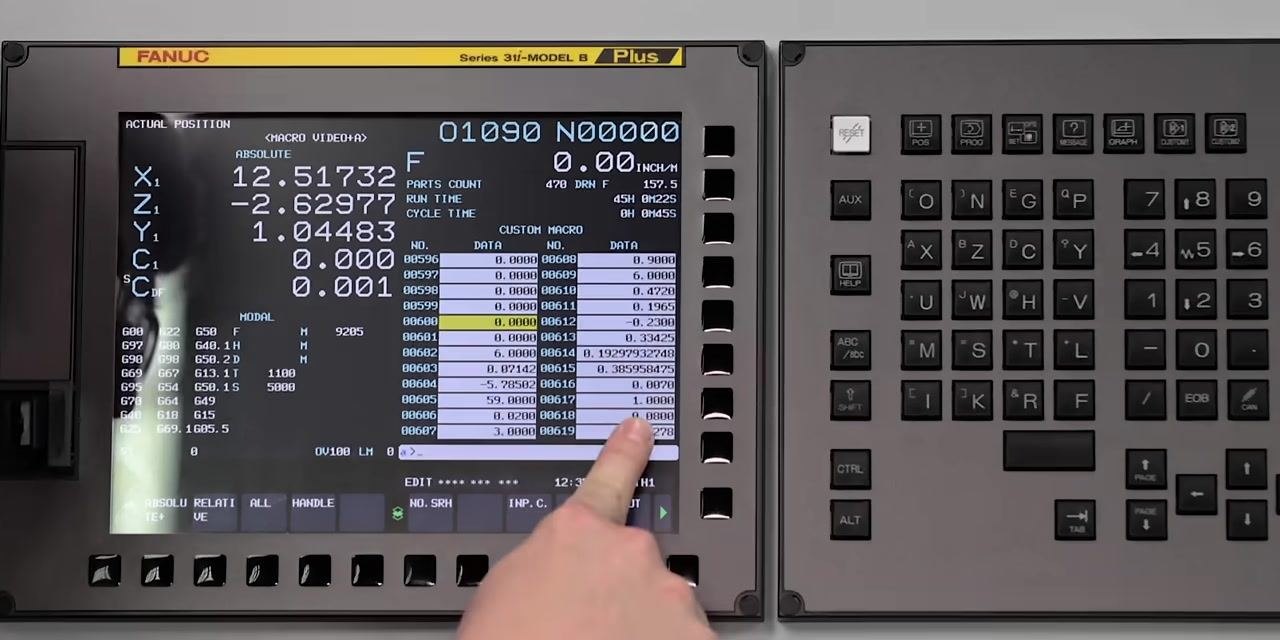
Confirm your macro variables are available
Before writing any code, confirm that the macro variables you plan to use are not already reserved by the machine or its subprograms. Different manufacturers reserve certain macro variables for specific functions, such as tailstock position, so checking first prevents conflicts.
- Press OFFSET on the control panel.
- Use the arrow keys to navigate to the MACRO section.
- Press MACRO to open the macro variable screen.
- Enter the variable number you intend to use and confirm it is not currently assigned.
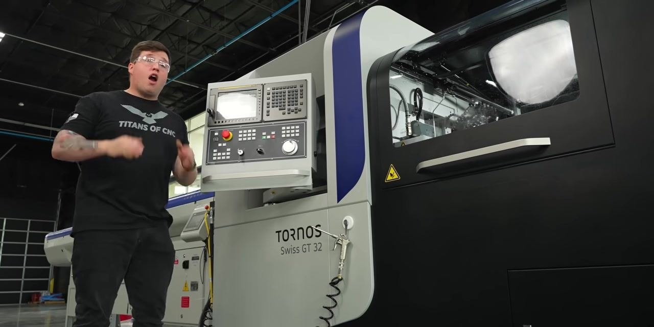
Identify an unused variable for the tool counter
In this example, variable #600 is selected as the tool counter. Review the macro variable table on your control to confirm the variable shows as available before assigning it.
Review variables already in use
Some macro variables may already be populated by other macros, such as a thread macro. Review the table to see which variables hold data and which are empty so you avoid overwriting important values.

Confirm variable assignments before proceeding
Look closely at which variables are currently holding data versus which are set to zero or empty. This check prevents you from accidentally assigning a variable that another macro already relies on.
You will use two macro variables for this procedure: #600 for the tool counter and #601 for the maximum tool life. Placing the maximum tool life variable at the top of the program keeps it easy to find and adjust later.
Set the maximum tool life
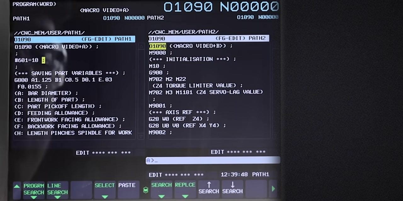
At the top of your CNC program, add the following line to define the maximum tool life:
#601=10 ;
This sets the maximum tool life to 10 cycles, meaning the tool can produce 10 parts before the macro triggers a fault.
The value 10 represents the maximum number of cycles, or parts, the tool can produce before the macro fault activates.

Locate the tool path in your program
Scroll to the end of the tool path section in your CNC program. This is where you will insert the line that increments the tool counter after each cycle.
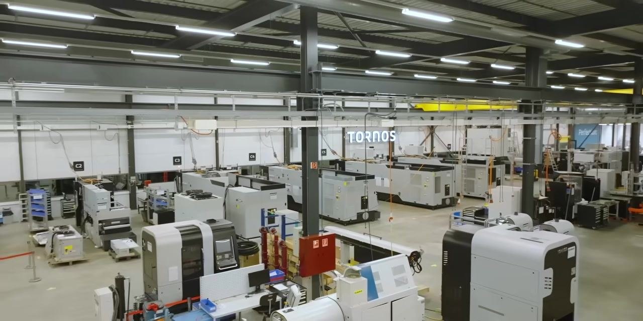
Add the tool counter increment
At the end of the tool path, insert the following line:
#600=#600+1 ;
This line increases the value of #600 by 1 each time the tool completes a cycle.
With both the maximum tool life variable and the counter increment in place, your program is ready for the logic that compares the two and triggers a fault when the limit is reached.
Choose a safe location for the fault check
Insert the fault logic immediately after the cutoff operation, not before. Faulting out before cutoff would leave a half-finished part in the spindle, creating a safety hazard and operational disruption.
Add the IF statement for tool life
Use an IF statement to check whether the tool counter has reached or exceeded the maximum tool life:
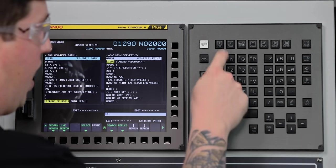
IF[#600 GE #601] GOTO 1234 ;
This means: if the value of #600 (tool counter) is greater than or equal to #601 (maximum tool life), jump to sequence number N1234.
Review supported macro conditional statements
Macro programming supports several conditional and logical statements: IF [ ], WHILE [ ], AND [ ], and THEN [ ]. For this tool life logic, you only need the IF statement.
Understand the IF statement structure
Think of the IF statement in simple terms: IF [condition] GOTO [action]. In your program, the condition is tool life rather than any everyday example — the logic works the same way regardless of what is being checked.
Break down the IF statement syntax
In the line IF[#600 GE #601] GOTO 1234 ;, #600 is your tool counter, GE stands for "greater than or equal to," and #601 is your maximum tool life. If the condition is true, the program jumps to sequence number N1234.
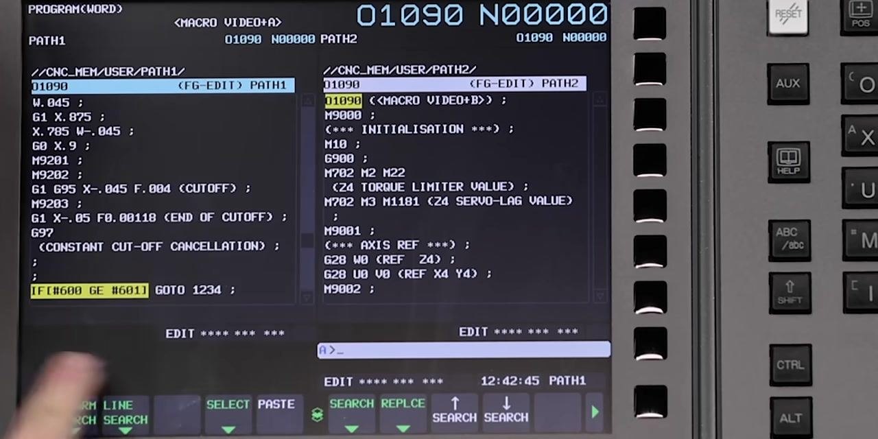
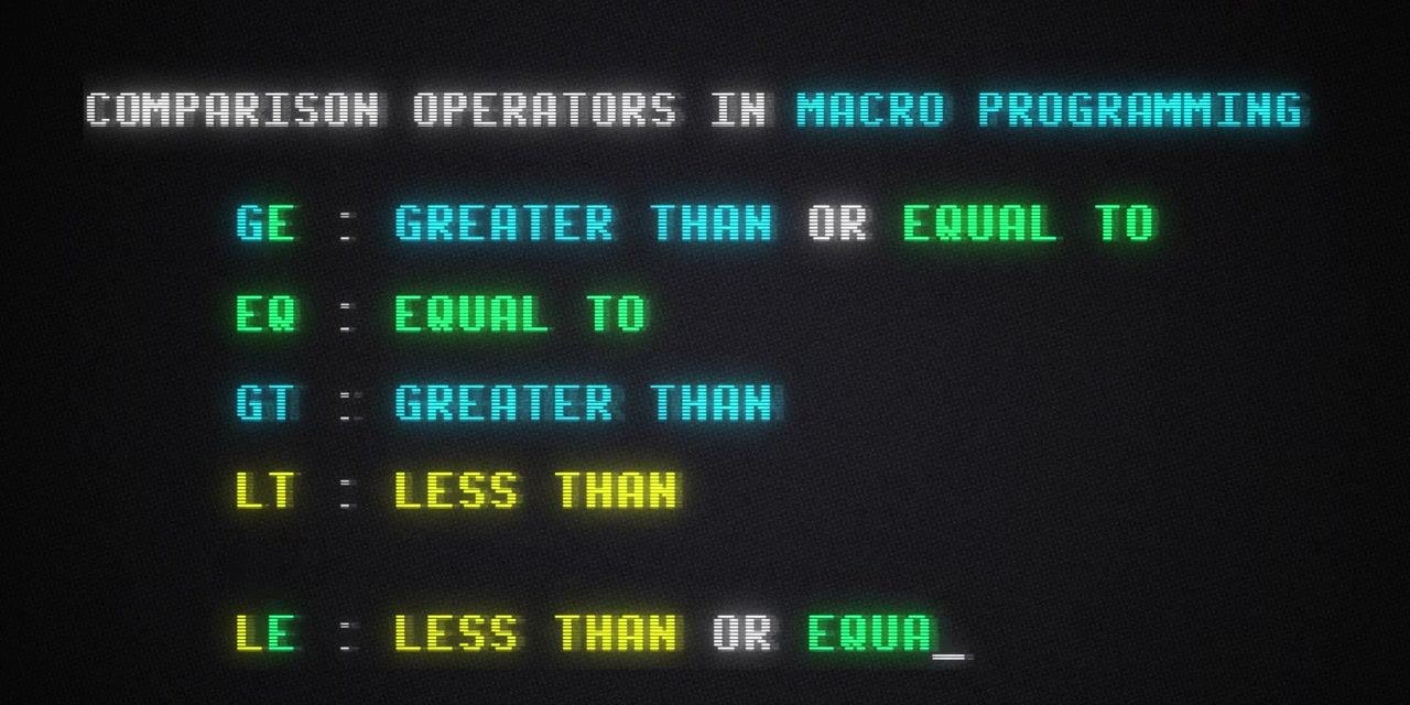
Learn the comparison operators
Macro programming supports these comparison operators for building conditions:
GE— greater than or equal toEQ— equal toGT— greater thanLT— less thanLE— less than or equal to
Understand the GOTO statement
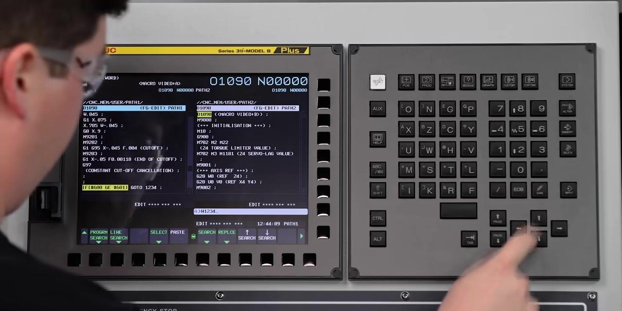
The GOTO command jumps to any sequence number (N number) in your program. For example, GOTO 1234 jumps to the line labeled N1234, allowing you to direct program flow based on a condition.
Search for the target sequence number
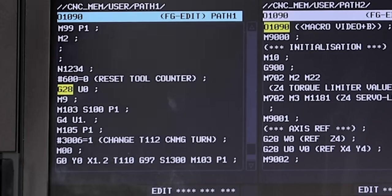
Use the control's search function to locate N1234 in your program. Enter N1234 on the keyboard and use the arrow keys to navigate to that sequence, where you will add logic to reset the counter, turn off coolant, and position the machine for the tool change.
Reset the tool counter
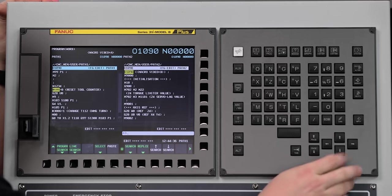
At sequence N1234, add the line:
#600=0 (RESET TOOL COUNTER);
This resets the tool counter to zero as the first step in the tool change sequence.
The steps that follow may vary depending on your machine type, such as a turret lathe versus a gang tool lathe. Always refer to your machine's manual for machine-specific instructions.
Move the axis to a safe position
Add the line G28 U0; to move the axis to a reference (safe) position, ensuring the tool is clear of the workpiece and safely positioned for the tool change or maintenance.
Turn off the coolant
Add the line M9; to turn off the coolant. This prevents coolant from running while an insert is changed or maintenance is performed.
Slow and stop the spindle
Add the following lines in sequence:
M103 S100 P1;
G4 U1.;
M105 P1;
The first line slows the spindle to 100 RPM, the second dwells for 1 second, and the third stops the spindle completely. The display shows a message confirming the spindle has stopped.
Display an operator message and pause the program
Add the line:
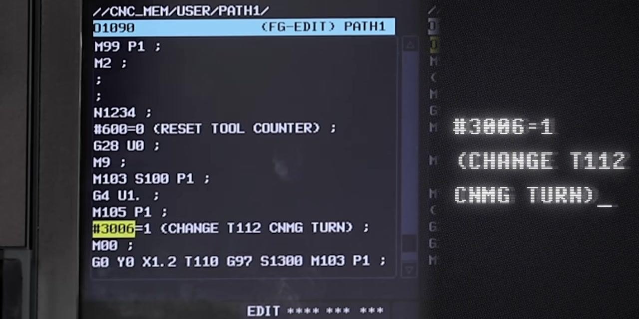
#3006=1 (CHANGE T112 CNMG TURN);
Any text placed in parentheses after #3006=1 appears as a message to the operator — in this case, "CHANGE T112 CNMG TURN." Keep messages clear and operationally relevant, since this text is intended to guide the operator's next action.
Safety note: Once this message displays, the machine faults out and prevents further operation until the message is acknowledged and the required action, such as a tool change, is completed. You cannot press start until the issue is resolved and the message is cleared.
Consider M00 as an alternative to a custom message
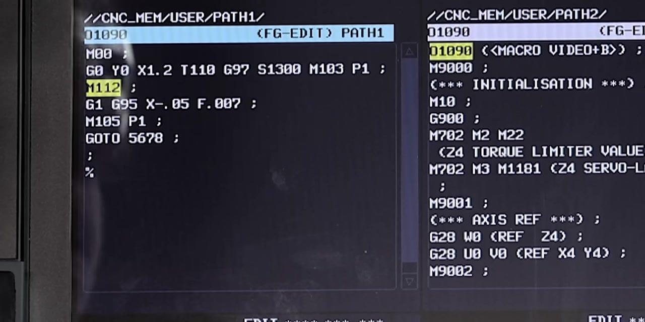
If your operators are well-trained and know what to look for, you can place an operator note on the M00 (program stop) line instead of a custom message. This method relies on operator awareness rather than an automated message, so use it only where your team is experienced with the program's structure.
Use GOTO to resume the program after the stop
After stopping the spindle and completing the required action, use a GOTO statement to continue the program from a specific line, for example:
GOTO 5678;
Use numeric labels, such as 5678, without the N prefix in the GOTO statement itself.
Navigate to the target line number
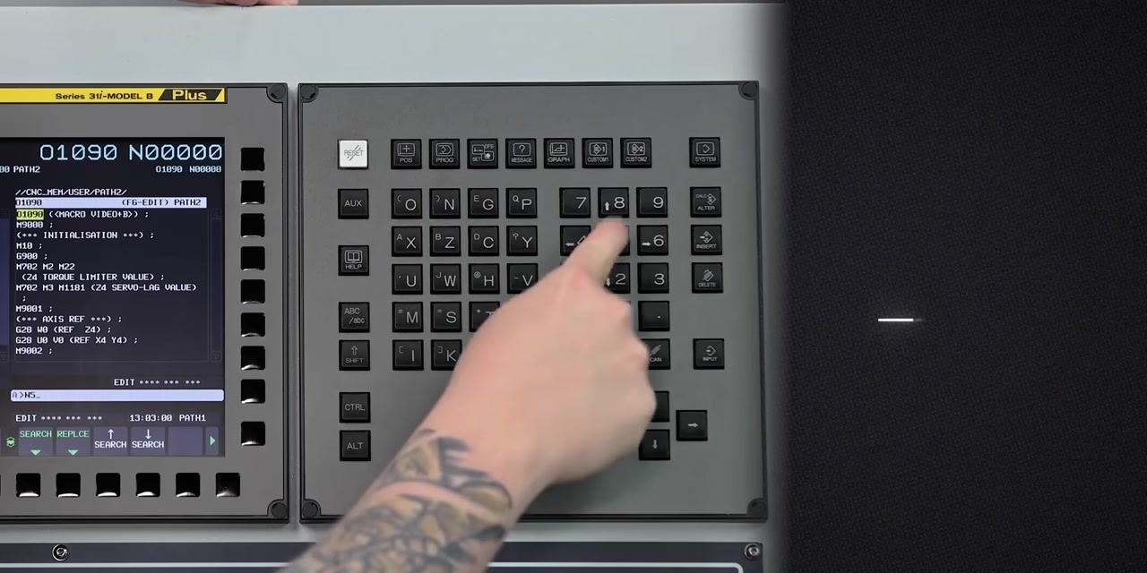
To jump to a specific line, enter the line number, such as N5678, using the keypad, and press the appropriate navigation key to move directly to that line.
Resume the program after the tool change
Once the tool change or maintenance is complete, press the start button to resume execution. The program restages everything as needed and continues automatically from the specified line.
Note: Tool counting menus can vary significantly between different CNC machines and can be confusing to learn due to differences in interface and terminology. Using programmatic messages and stops, as described above, standardizes the tool change process across different machines and reduces the learning curve for operators.
Review the complete macro logic
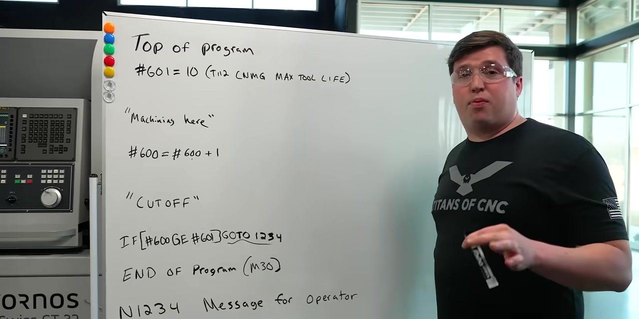
The full macro structure follows this pattern:
#601 = 10 (T112 CNMG MAX TOOL LIFE)
"Machining here"
#600 = #600 + 1
"CUTOFF"
IF[#600 GE #601] GOTO 1234
END OF Program (M30)
N1234 Message for Operator
These lines work together to automate tool life tracking and operator notification.
After each machining operation, the tool counter variable increments by one, ensuring accurate tracking of tool usage.
After machining and incrementing, the program executes the cutoff operation, then checks whether the tool counter has reached or exceeded the maximum tool life using IF[#600 GE #601] GOTO 1234. If the condition is met, the program jumps to line 1234, where the operator message is located.
The program repeats the machining and increment steps until the tool counter reaches the set limit (10 in this example). Once the condition is met, the program jumps past M30 (end of program) to display the operator message, instructing them to change the insert and restage the machine, minimizing downtime.

Run a test part to confirm the logic
Run additional parts to confirm the macro logic in a real-world scenario before relying on it in production.
Complete the final cycle and return to home position
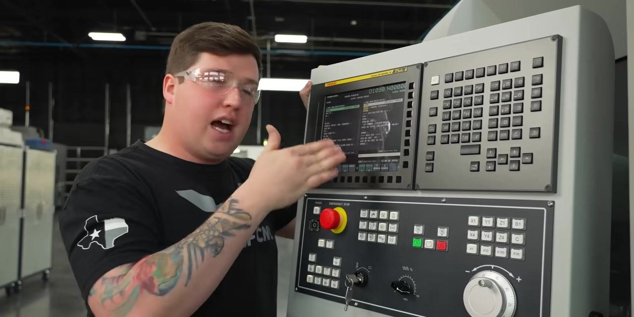
Once the final part completes, the CNC machine returns to its home or rest position. The setup includes tool holders, coolant lines, and a monitoring camera. The machine is now ready to check the tool counter and display the operator message if needed.
Confirm the operator message appears
The CNC control panel displays the message "CHANGE T112 CNMG TURN," confirming the tool change condition has been met. The screen also shows part count, run time, and other relevant data.
Prepare to perform the tool change
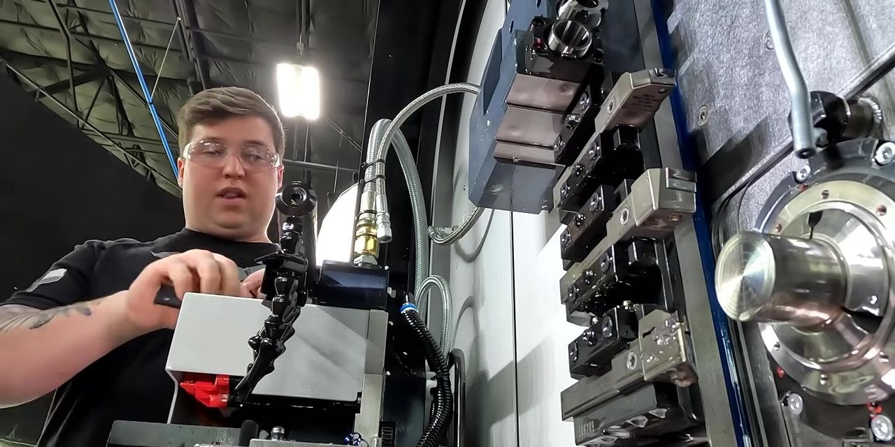
Approach the CNC machine to perform the required tool change. The tool turret, spindle, and surrounding machine components are visible as you prepare to replace the worn insert, following the message prompt.
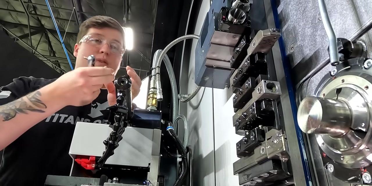
Remove the current insert
PPE required: Wear safety glasses before handling the tool holder or insert.
Use the appropriate tool to loosen and remove the current insert from the tool holder inside the CNC machine. Hold the replacement insert ready for installation.
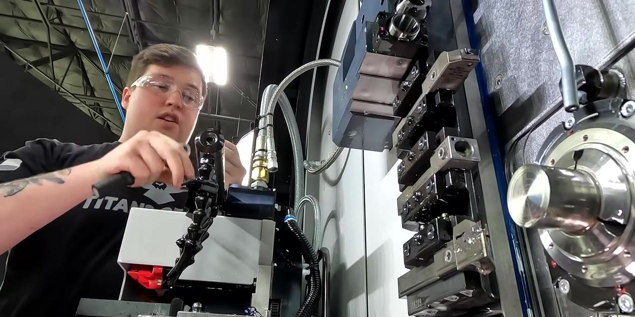
Install the new insert
Place the new insert into the tool holder and secure it by tightening it with the appropriate tool.
Confirm the insert is properly seated and secured before continuing, so the machine is ready for the next operation.
Verify the machine after the insert change
Return to the CNC control panel and check the machine interface to confirm it is ready for operation after the insert change.
Verification and summary
Confirm the following before returning the machine to production:
- The macro variables
#600(tool counter) and#601(maximum tool life) are defined at the top of the program. - The tool counter increment line
#600=#600+1 ;sits at the end of the tool path. - The IF statement
IF[#600 GE #601] GOTO 1234 ;is placed immediately after the cutoff operation. - Sequence
N1234resets the counter, turns off coolant, stops the spindle, and displays the operator message. - A
GOTOstatement resumes the program after the tool change is completed and start is pressed. - The new insert is installed, seated, and secured, and the control panel confirms the machine is ready.
Key program lines for reference:
#601=10 ;— sets the maximum tool life.#600=#600+1 ;— increments the tool counter after each cycle.IF[#600 GE #601] GOTO 1234 ;— checks tool life and triggers the jump.#600=0 (RESET TOOL COUNTER);— resets the counter.G28 U0;,M9;,M103 S100 P1;,G4 U1.;,M105 P1;— move to safe position, stop coolant, and stop the spindle.#3006=1 (CHANGE T112 CNMG TURN);— displays the operator message and pauses the program.GOTO 5678;— resumes the program at the specified line after the tool change.
Always follow your specific machine's safety and operational guidelines, since the steps above are a general example that may require adaptation for your equipment.
What's next
Once you are comfortable writing a tool counting macro, you can explore additional macro programming resources, including trigonometric functions such as tangent, sine, and cosine, to expand what your macros can calculate and control.
As you gain experience, consider which additional macros — such as tool life tracking variations, custom operator messages, or other conditional logic — would be most useful for your own CNC programs.



Generation details: cost, quality tiers
Docsie billed 6,500 credits ($4.55) to analyze this 13-minute video at standard quality. The rewrite, template fill and Word/PDF exports were included. The same video at each quality tier:
| Quality | Frames sampled | Credits | Approx. cost |
|---|---|---|---|
| Draft | every 16-30 s | 3,250 | $2.27 |
| Standard (this guide) | every 8-15 s | 6,500 | $4.55 |
| Detailed | every 4-7 s | 13,000 | $9.10 |
| Ultra | every 1-3 s | 26,000 | $18.20 |
Credits priced at $0.70 per 1,000; plans include a monthly allowance. Enterprise customers on on-premise or bring-your-own-model deployments run this on their own inference and pay no per-video credits.
Generated by Docsie Video-to-Docs on 2026-09-14 from a 12-minute video. Screenshots are frames from the source video and belong to their creator, TITANS of CNC MACHINING, whose original is embedded above. If you own this video and want the guide removed or credited differently, contact us and we will act within one business day.