
How to Wire a PLC
This standard operating procedure explains how to wire a PLC, covering how digital and analog signals from field devices—such as valves, switches, and transmitters—are connected to a PLC's input and output modules. Following a practical example, this procedure walks through identifying the relevant modules, preparing wires, and terminating them correctly using front connectors and wire ferrules.
Video: How to Wire Sensors to a PLC - Part 1 by RealPars (2016). All credit for the demonstration goes to the creator; watch the original on YouTube. The written guide below was generated from this video by Docsie. Creator? Request a change or removal.
This standard operating procedure explains how to wire a PLC, covering how digital and analog signals from field devices—such as valves, switches, and transmitters—are connected to a PLC's input and output modules. Following a practical example, this procedure walks through identifying the relevant modules, preparing wires, and terminating them correctly using front connectors and wire ferrules.
Purpose
The purpose of this procedure is to provide a reliable, repeatable method for wiring field devices to PLC input and output modules, ensuring safe and professional connections.
Scope
This procedure applies to wiring digital and analog field devices—including solenoid valves, pressure transmitters, temperature transmitters, and switches—to a Siemens PLC rack using front connectors. It covers module identification, front connector installation, and wire termination using ferrules.
Required equipment
- Siemens PLC rack with input/output modules (for example, the S7-300 Analog Input Module labeled AI 8x12BIT)
- Front connector compatible with the target PLC module
- Field device wiring (from switches, valves, temperature transmitters, and pressure transmitters)
- Wire ferrules
- Wire stripper
- Crimping tool
Procedure
Step 1: Identify the field devices and wiring layout
Review a wiring diagram showing the PLC mounted on a DIN rail with its connected field devices: a solenoid valve, a pressure transmitter, and a temperature transmitter. Note the wiring paths running from each device to the PLC modules.
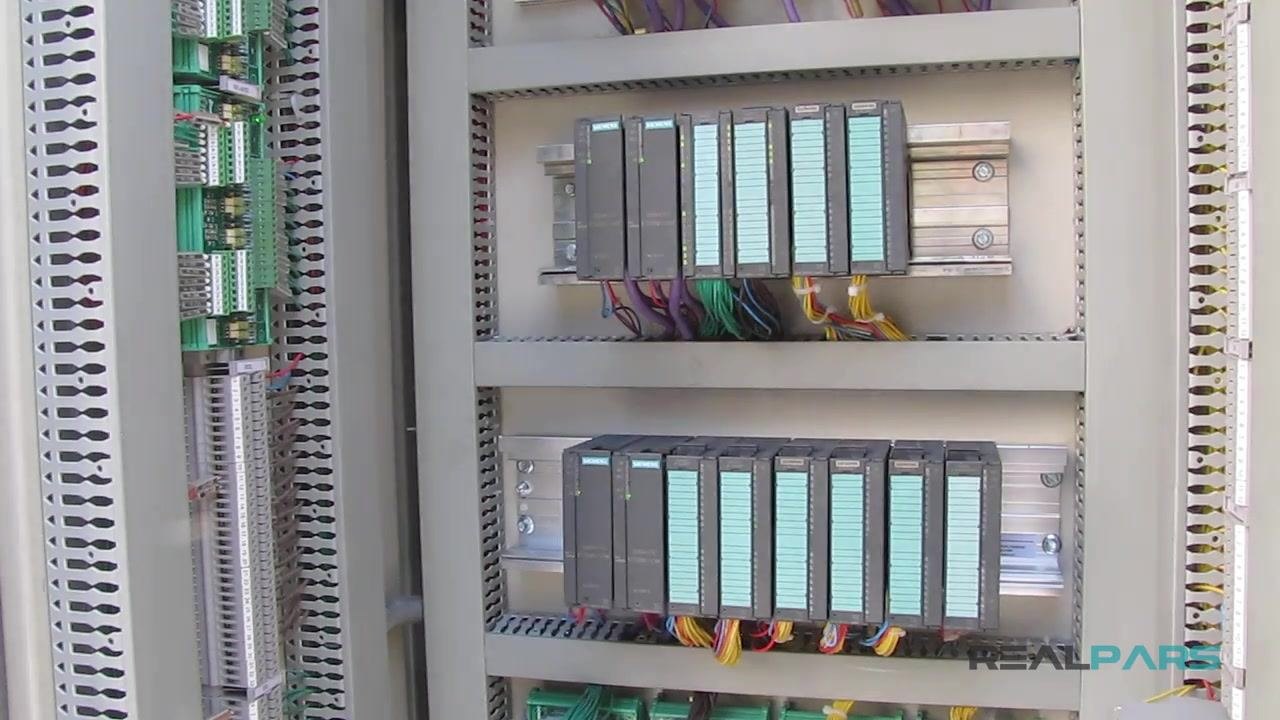
Step 2: Examine a real PLC cabinet for orientation
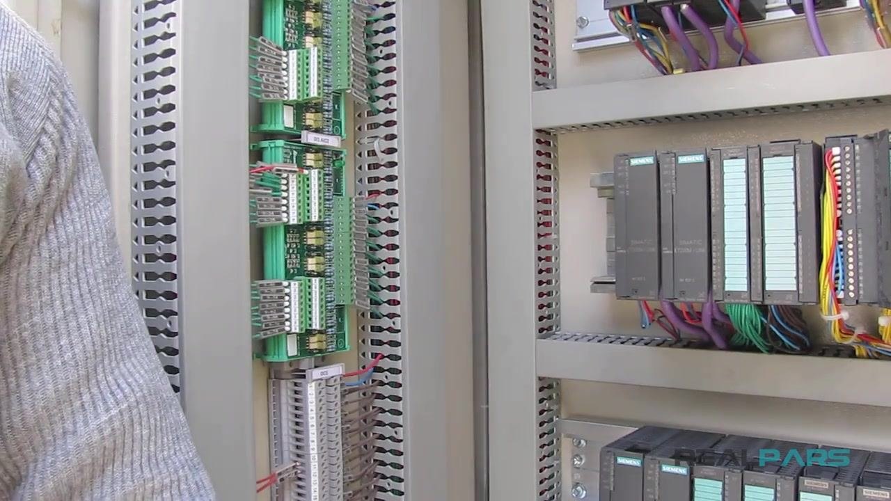
Inspect an actual industrial control panel with multiple PLC modules installed in organized rows. Observe the colored wiring (purple, green, yellow, red) running from the modules to terminal blocks and out to field wiring. Use this view to orient yourself before beginning any wiring work.
Step 3: Review the field device types you will wire
Confirm the categories of field devices you will be connecting: switches, valves, temperature transmitters, and pressure transmitters. These device types correspond to the terminals you will wire in later steps.
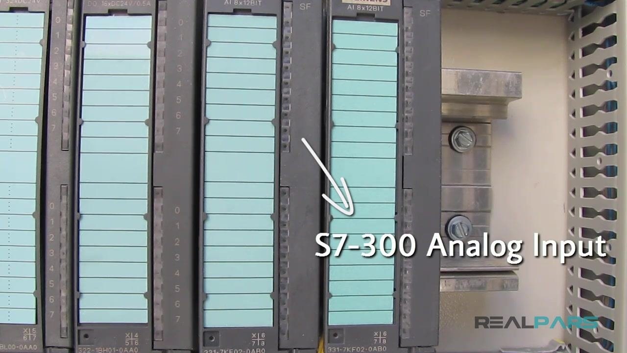
Step 4: Locate the target module on the PLC rack
Locate the module you will be wiring—in this example, the S7-300 Analog Input Module labeled AI 8x12BIT—within the PLC rack. Confirm the module labels and part numbers match the module you intend to wire.
Step 5: Open the module's front door
Open the front door of the module. Note that the module itself has no visible terminals for wiring connections—wiring is not done directly on the module body.
Step 6: Inspect the internal view of the module
Examine the inside of the module after opening the front cover. You will see internal connectors and printed wiring diagrams, but still no obvious wiring terminals. This confirms that a separate front connector accessory is required for wiring.
Step 7: Obtain and install the front connector
Purchase a front connector designed specifically for your PLC module. Before installing it, wire all control signals from your field devices to the terminals on the front connector. To install:
- Hold down the module lock on the PLC module.
- Align the front connector with the module and push it in firmly until fully seated.
- Confirm the connector is properly locked in place.
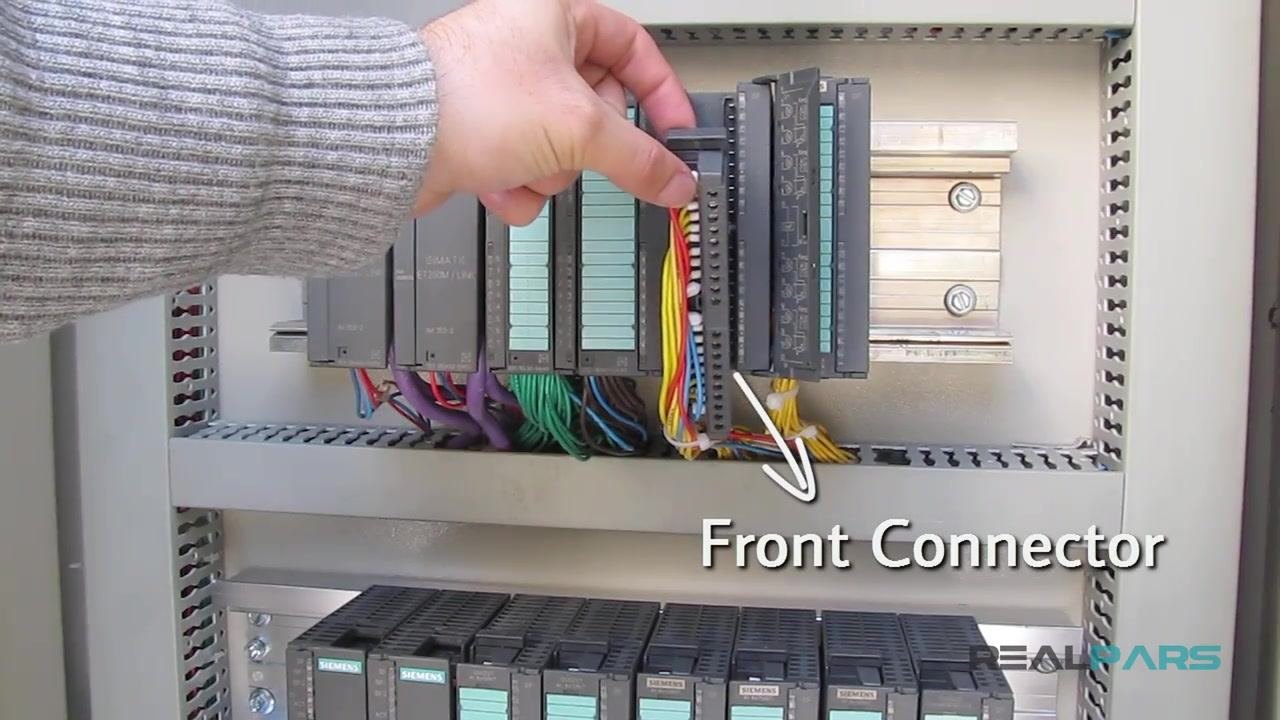
Step 8: Connect wires to the front connector using ferrules
Always use wire ferrules when wiring control signals to the front connector terminals; they ensure a secure and reliable connection. Attach a ferrule to the end of each wire before inserting it into the appropriate terminal, then tighten the terminal screw.
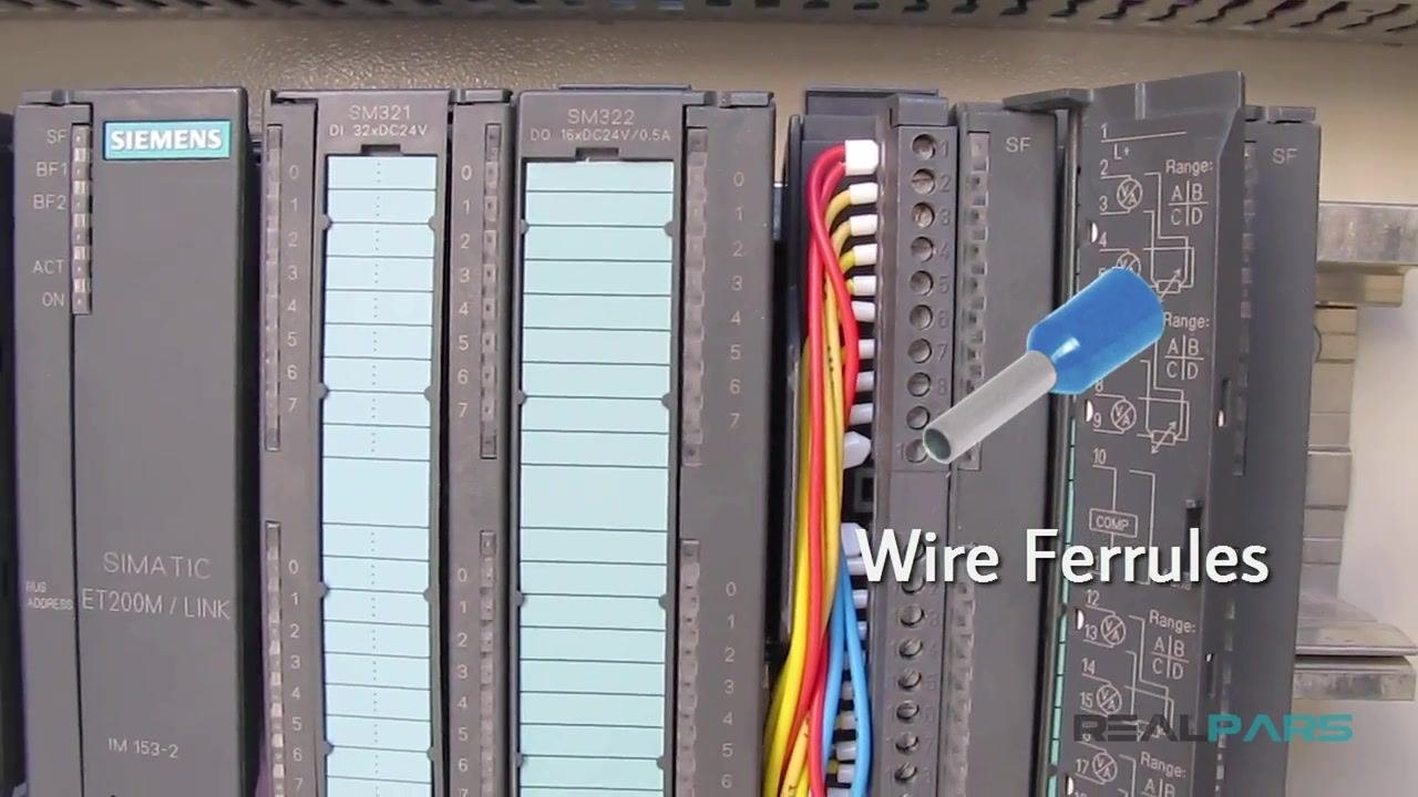
Step 9: Strip the wire for ferrule attachment
Use a wire stripper to remove insulation from the end of the wire, exposing the bare conductor. Strip only enough insulation to match the length of the ferrule—stripping too much or too little will affect the connection quality.
Step 10: Crimp the ferrule onto the wire
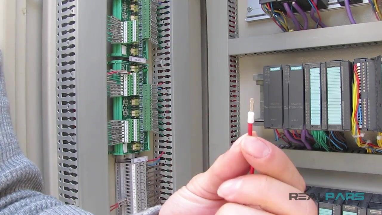
Slide the stripped end of the wire into the ferrule. Use a crimping tool to firmly compress the ferrule onto the wire by squeezing the tool's handles. Confirm the ferrule does not move or slip off the wire after crimping.
Step 11: Verify the crimped connection
Inspect the crimped ferrule to confirm it is properly attached and the connection is solid. The wire should be securely held inside the ferrule with no exposed strands visible.
Step 12: Prepare the finished wire for installation
Once crimped, hold the finished wire to confirm it is straight and undamaged before inserting it into the front connector terminal and tightening the terminal screw. Repeat the stripping, ferrule attachment, and crimping process for every control signal wire that needs to be connected to the module.
Verification
Before closing the module, confirm the following:
- Each wire has a properly crimped ferrule with no exposed strands.
- All terminal screws on the front connector are tightened securely.
- The front connector is fully seated and locked onto the PLC module.
- All required field device signals (switches, valves, temperature transmitters, pressure transmitters) are wired to the correct terminals.
Summary
By following this procedure, you now know how to wire a PLC by identifying the correct module, installing a front connector, and terminating field device wiring using properly stripped and crimped ferrules. This process ensures a safe, reliable, and professional connection between field devices and PLC input/output modules.
Generation details: cost, quality tiers
Docsie billed 3,000 credits ($2.10) to analyze this 6-minute video at standard quality. The rewrite, template fill and Word/PDF exports were included. The same video at each quality tier:
| Quality | Frames sampled | Credits | Approx. cost |
|---|---|---|---|
| Draft | every 16-30 s | 1,500 | $1.05 |
| Standard (this guide) | every 8-15 s | 3,000 | $2.10 |
| Detailed | every 4-7 s | 6,000 | $4.20 |
| Ultra | every 1-3 s | 12,000 | $8.40 |
Credits priced at $0.70 per 1,000; plans include a monthly allowance. Enterprise customers on on-premise or bring-your-own-model deployments run this on their own inference and pay no per-video credits.
Generated by Docsie Video-to-Docs on 2026-09-14 from a 5-minute video. Screenshots are frames from the source video and belong to their creator, RealPars, whose original is embedded above. If you own this video and want the guide removed or credited differently, contact us and we will act within one business day.