
How to Weld Cast Iron
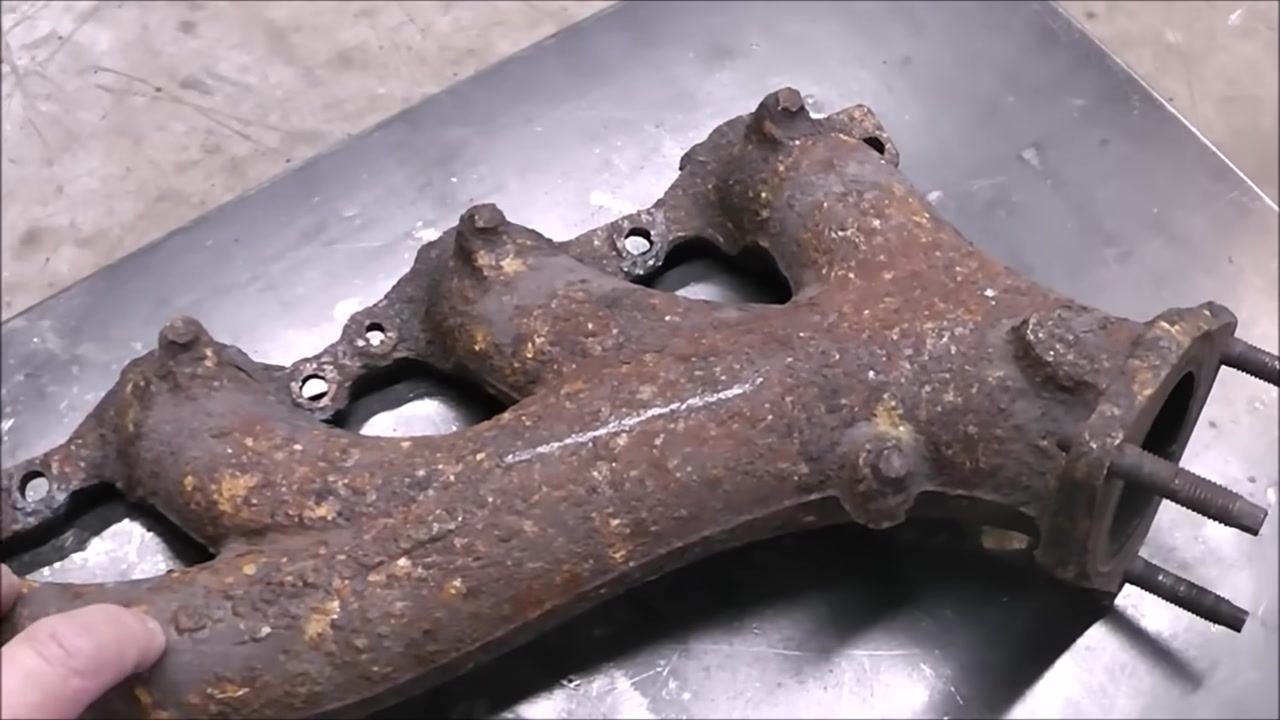
This procedure explains how to weld cast iron using a stick welder and Muggy Weld electrodes. It walks through preparing a cracked cast iron part, selecting the correct rod, running controlled weld beads, and finishing the repair so it blends seamlessly with the surrounding metal. This method is demonstrated on a cracked exhaust manifold sourced from a scrapyard, but the same approach applies to other cast iron parts that need crack repair.
Video: Stick Welding Cast Iron Repair with Muggy Weld by Brandon Lund (2018). All credit for the demonstration goes to the creator; watch the original on YouTube. The written guide below was generated from this video by Docsie. Creator? Request a change or removal.
This procedure explains how to weld cast iron using a stick welder and Muggy Weld electrodes. It walks through preparing a cracked cast iron part, selecting the correct rod, running controlled weld beads, and finishing the repair so it blends seamlessly with the surrounding metal. This method is demonstrated on a cracked exhaust manifold sourced from a scrapyard, but the same approach applies to other cast iron parts that need crack repair.
Purpose
The purpose of this SOP is to provide a repeatable process for stick welding cast iron without cracking the base metal. Cast iron has a high carbon content that makes it strong but brittle — it will break before it bends. Mild steel, by contrast, has lower carbon content and is more ductile, so it can be heated to cherry red and cooled without issue. Cast iron cannot be treated the same way: rapid heating and cooling can cause it to crack, so temperature control throughout the process is critical.
Scope
This procedure covers:
- Confirming that a workpiece is cast iron using a spark test.
- Preparing a cracked cast iron part for welding, including grinding, drilling, and grooving the crack.
- Selecting between Muggy Weld 72 Cast Iron Weld and Muggy Weld 77 Cast Iron Weld rods based on the condition of the part.
- Running controlled weld beads, cooling, peening, and adjusting machine settings.
- Finishing the repair so it is visually indistinguishable from the surrounding metal.
Required equipment and PPE
- Angle grinder with a 40-grit abrasive wheel
- Angle grinder with a diamond-tipped Lennox Metal Max disc
- Angle grinder with a 60-grit abrasive disc
- Angle grinder with an 80-grit flap wheel
- Hand drill with a 3/16" drill bit
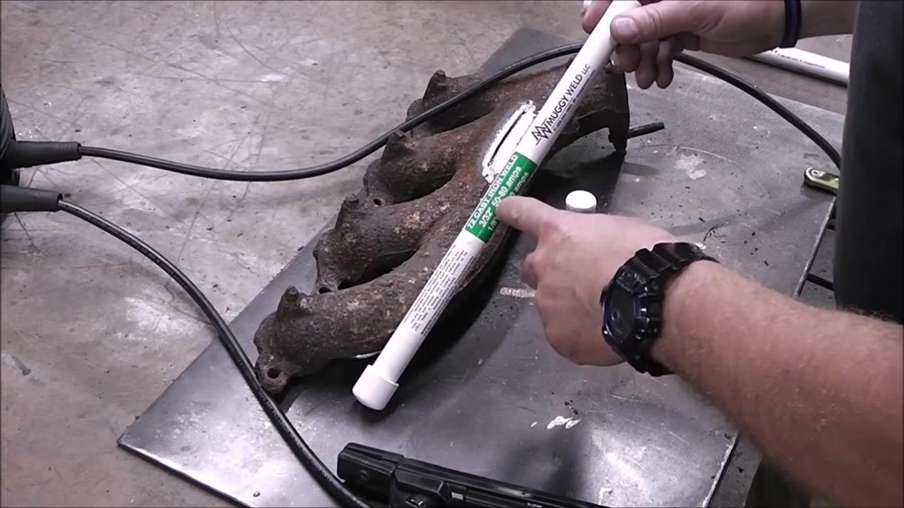
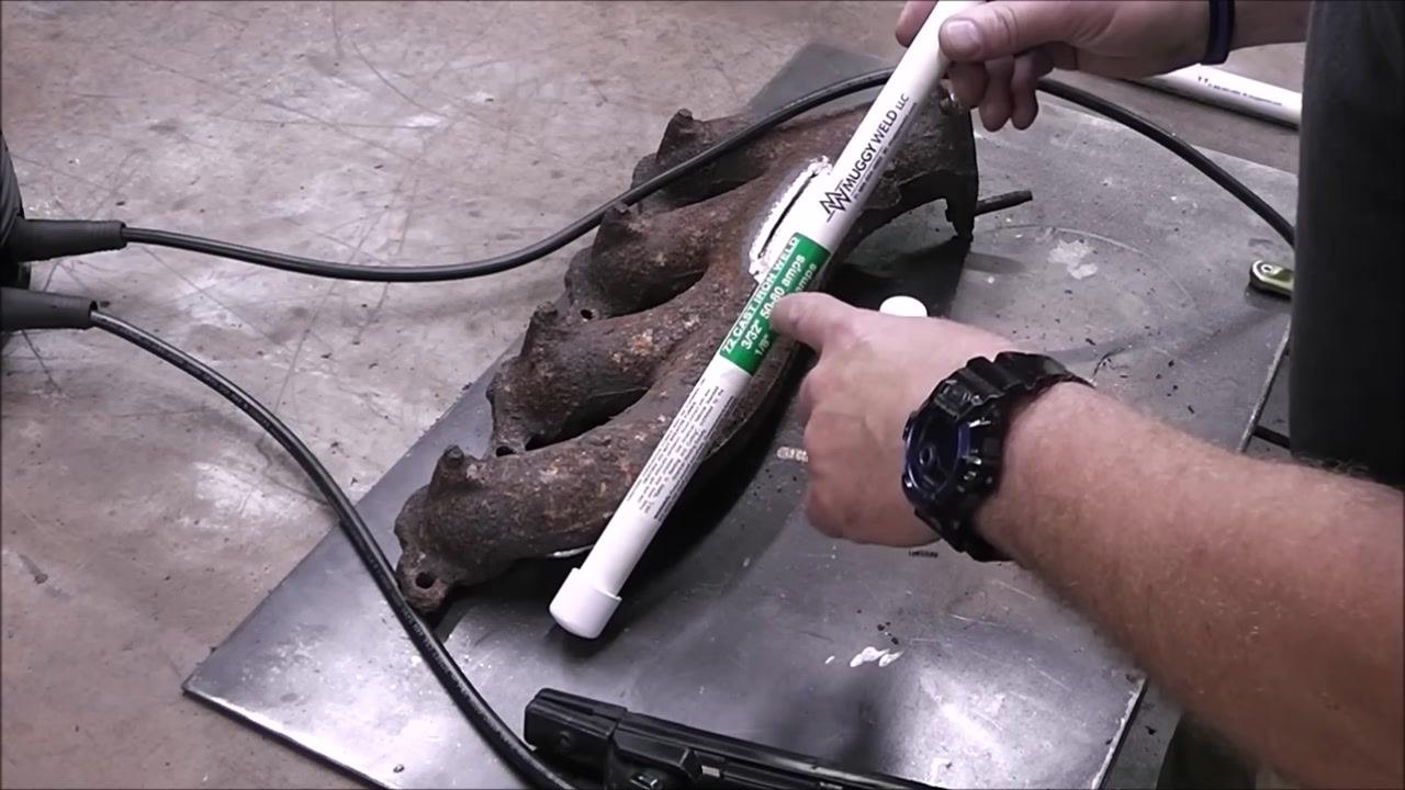
- Muggy Weld 72 Cast Iron Weld rod (3/32", rated 50–80 amps; 1/8", rated 70–120 amps)
- Muggy Weld 77 Cast Iron Weld rod (3/32", rated 50–70 amps; 1/8", rated 60–110 amps)
- Stick welder (a Blue Demon 160 or a BlueArc 90STI / 160STI DC Inverter Arc Welder are shown in this procedure), with ground clamp and electrode holder
- Peening tool or chipping hammer
- Metal pointer or similar tool for tracing the crack
- Protective gloves
- Propane torch (optional, for preheating)
- A well-ventilated work area free of flammable materials
Prepare the workpiece and confirm the material
-
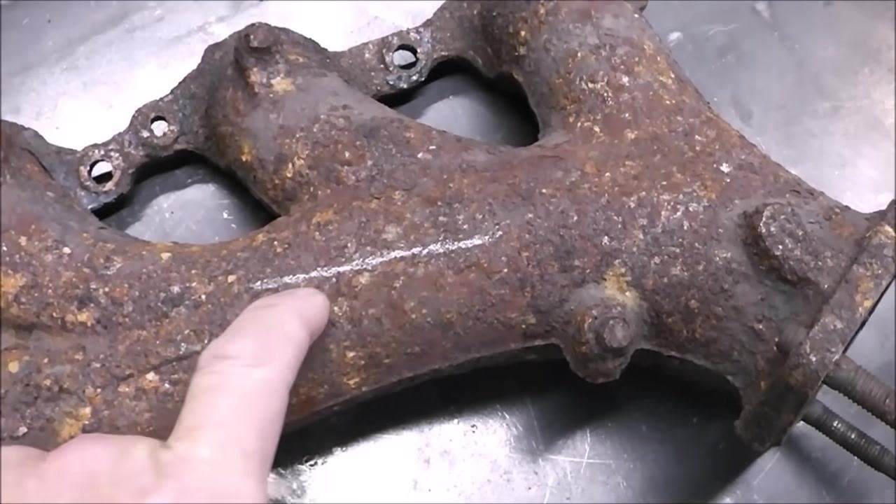
Place the cast iron part on a metal workbench and mark the area where the crack is located.
-
Mark the line of the crack with your finger or a pointer so the boundaries are clearly visible before grinding.
-
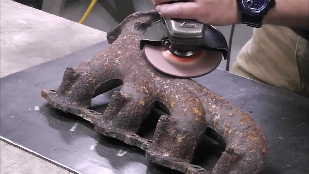
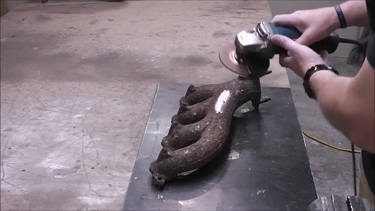
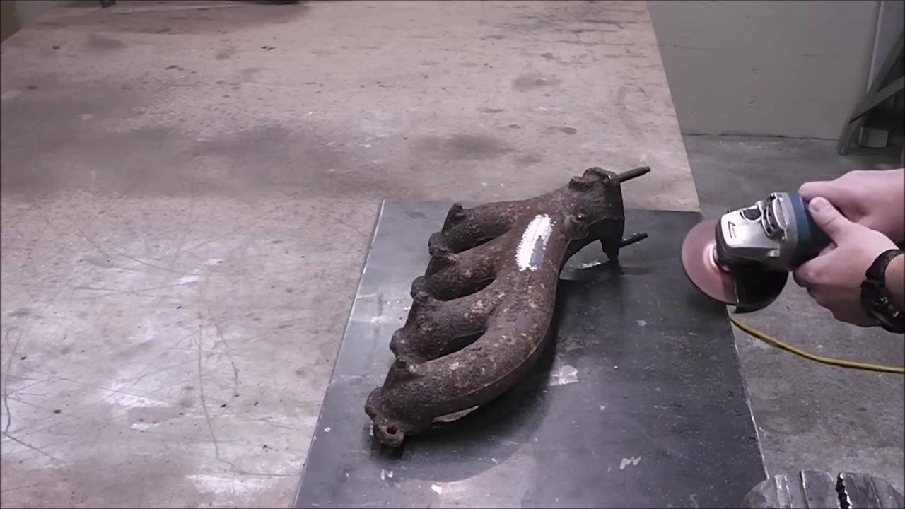
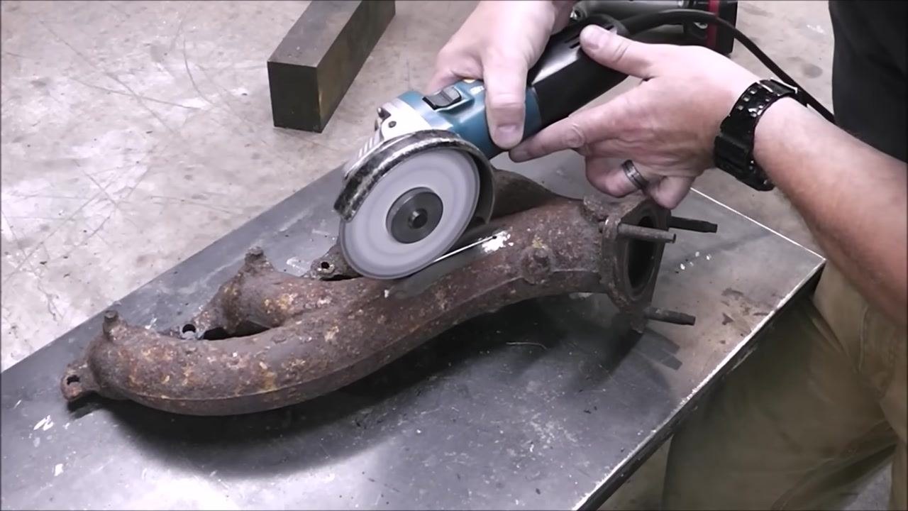
Grind the area around the crack using an angle grinder fitted with a 40-grit abrasive wheel. Grind until you reach bright, shiny metal, removing all rust and debris to maximize weld quality.
-
Continue grinding along the full length of the crack until the entire area is clean, bare metal. This exposes the surface needed for the best welding results.
-
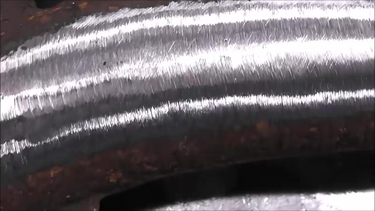
Perform a spark test to confirm the material. Touch the grinder to the cleaned area and observe the sparks: cast iron produces orangey-red, sparse sparks, while steel produces yellow, abundant sparks. Compare the sparks from the part to sparks from a known steel surface, such as the workbench.
-
Confirm the spark pattern matches cast iron. The orangey-red, low-volume spark stream verifies the workpiece is cast iron rather than steel.
-
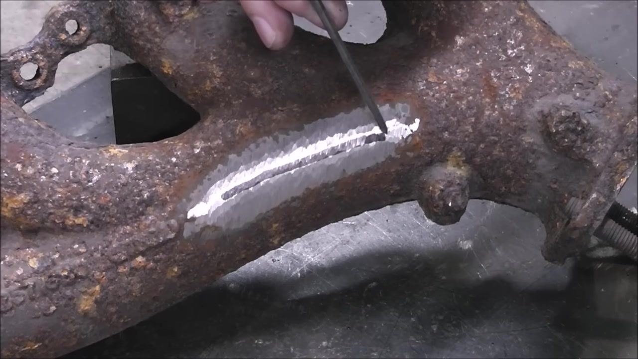
Trace the crack's path on the cleaned surface using a metal pointer to identify exactly where the crack begins and ends.
-
Mark both ends of the crack with the pointer so you know precisely where to drill.
-
Drill a 3/16" hole at each end of the crack, making sure the bit passes through the full thickness of the material at each crack tip. This step stops the crack from spreading further and is critical to a durable repair.
Groove the crack and select the welding rod
-
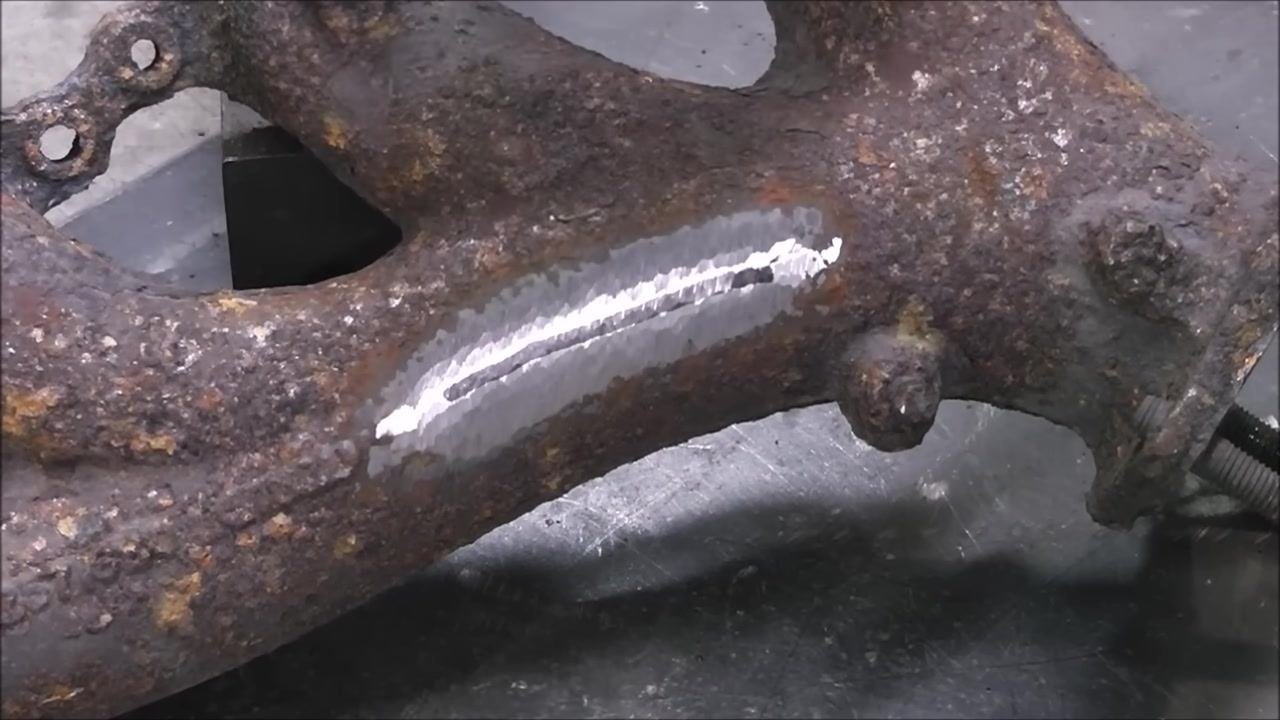
Confirm that the crack is confined between the drilled holes before proceeding to grooving.
-
Groove the crack using a diamond-tipped blade, such as a Lennox Metal Max disc mounted on an angle grinder. Grind carefully along the full length of the crack, between the drilled holes, to create a clean groove for welding.
-
Finish the groove by continuing to grind until it is uniform along its length and free of rust or contaminants.
-
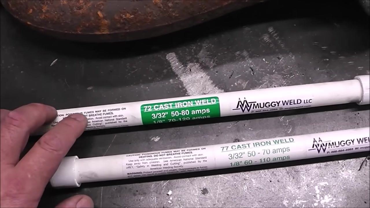
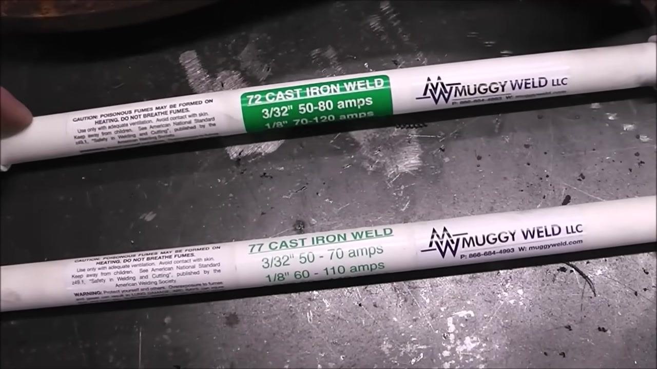
Lay out the two rod options and review their specifications. Muggy Weld 72 Cast Iron Weld is rated at 3/32" for 50–80 amps and 1/8" for 70–120 amps. Muggy Weld 77 Cast Iron Weld is rated at 3/32" for 50–70 amps and 1/8" for 60–110 amps.
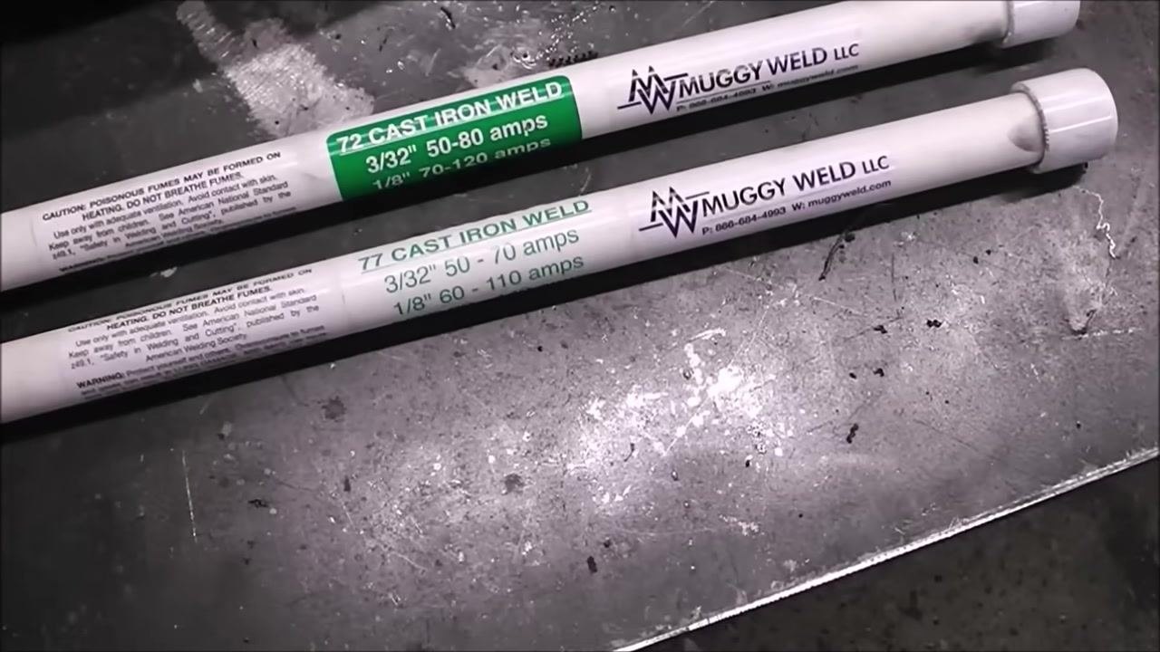
- Match the rod to the condition of the part. The 72 Cast Iron Weld rod is a nickel iron rod designed for joining dirty or contaminated cast iron, making it well suited to parts exposed to oil or heavy contamination, such as exhaust manifolds. The 77 Cast Iron Weld rod is a tri-metal core rod offering up to 300% more elongation than comparable products for superior crack resistance, and it is machinable after welding.
-
Select the rod for your application. Use the 72 rod for dirty, contaminated, or oil-soaked cast iron; use the 77 rod when you need maximum crack resistance and the ability to machine the weld afterward.
-
Have both rod types on hand before beginning the weld, in case conditions call for a change in selection.
Set up the welding machine
- Position the part on a clean, flat metal work surface, free of loose rust and debris, and place your selected Muggy Weld rod alongside it. Connect your welding machine, ground clamp, and electrode holder, and confirm the work area is well-ventilated and free of flammable materials.
- Select a 3/32" rod and set the machine to approximately 60 amps, as recommended for this rod size. Both the 72 and 77 rods are all-position rods, meaning they can be used flat, vertical, overhead, or in any other orientation.
Weld the crack in controlled beads
-
Position the rod on the prepared groove and plan to weld in short, controlled beads of no more than 1 inch at a time. After each bead, allow the part to cool completely before starting the next one — this prevents cracking caused by thermal stress. Repeat this process until the entire crack is filled.
-
Strike an arc and run a 1-inch weld bead along the prepared groove. Stop after each bead and let the part cool to room temperature before continuing; do not rush this step, as cooling is critical to avoiding cracks.
-
Peen the weld bead immediately while it is still hot, using a peening tool such as a small hammer or chipping hammer to gently tap the bead. Peening relieves stress in the weld and further reduces the risk of cracking.
-
Confirm the welding machine is connected and ready. Welding with no preheat, as shown here, is more challenging because of the rapid temperature change cast iron experiences. If possible, preheat the part to around 500°F (260°C) to reduce thermal shock and improve your chances of a crack-free weld.
-
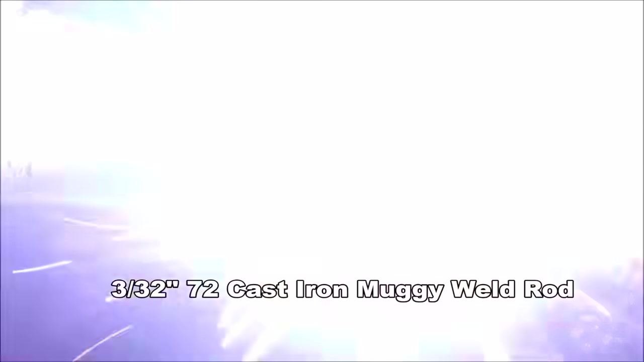
Begin welding with the 3/32" 72 Cast Iron Muggy Weld rod, maintaining a steady hand and a consistent arc length for best results.
-
If you choose to preheat, bring the part to approximately 500°F (260°C) using a torch or oven before welding. This step reduces the risk of cracking by lowering the temperature differential during welding.
Cool, peen, and inspect the weld
-
Let the completed bead cool down very slowly without disturbing or force-cooling the part. Slow cooling helps prevent cracking.
-
Peen the bead again while it is still hot, gently tapping it with a peening tool or chipping hammer to relieve internal stresses.
-
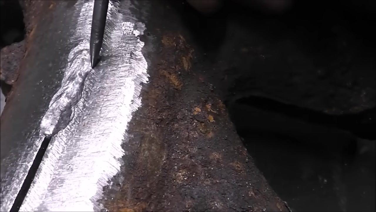
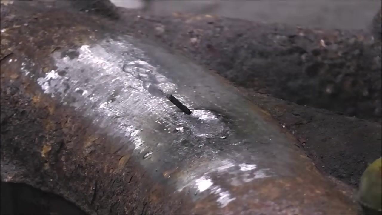
Inspect the bead for undercut — a groove melted into the base metal next to the weld. Undercut indicates that the welding settings may be too hot or that technique needs adjustment.
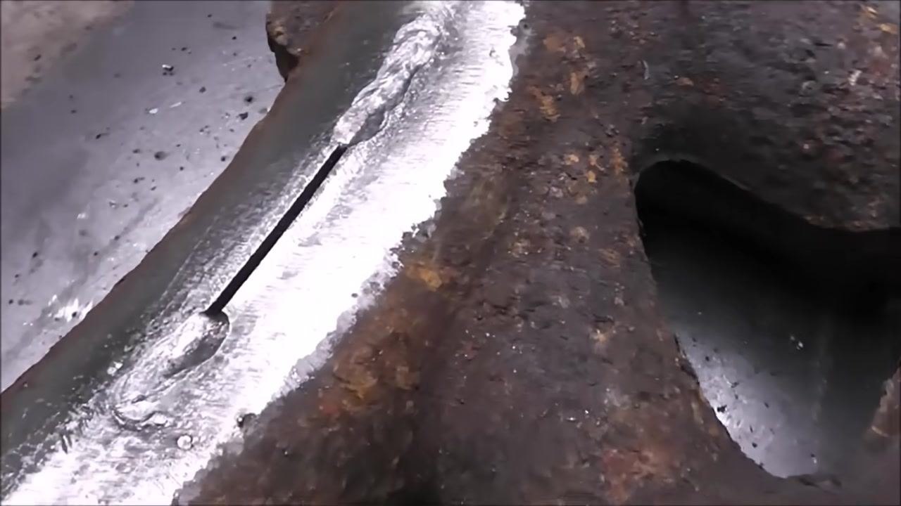
- Run a tool or your finger gently along the bead to feel for ridges or grooves. A slight ridge indicates the machine settings are a bit too hot.
Fine-tune machine settings for weld quality
-
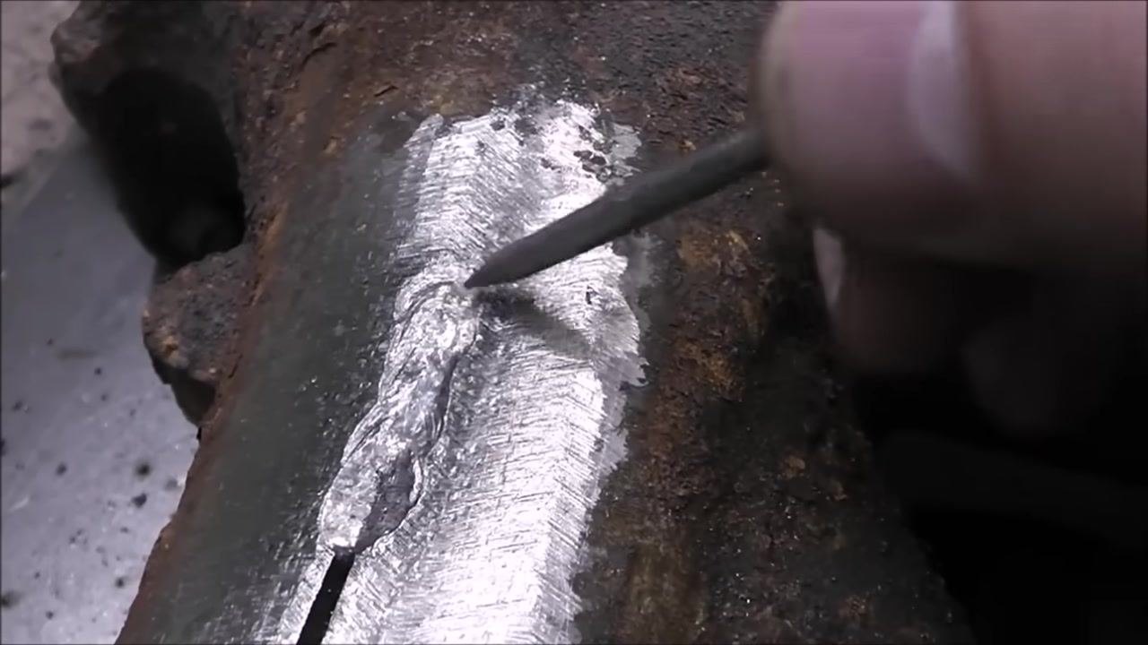
Reduce the amperage if you notice undercut or excessive heat. In this example, the machine is adjusted from around 60 amps down to 51 amps on a BlueArc 160STI DC Inverter Arc Welder.
-
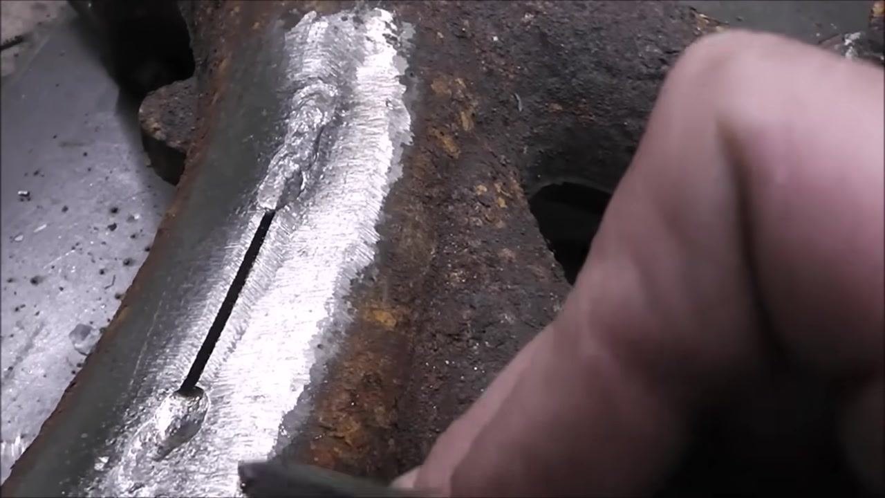
Resume welding with the adjusted setting, continuing to run short beads and allowing slow cooling and peening after each one.
Master electrode technique
-
Hold the electrode at a slight angle to the workpiece and move it in a motion similar to sharpening a pencil. This exposes fresh electrode material and helps maintain a stable arc.
-
Maintain the same sharpening motion consistently to keep the electrode tip clean and exposed. This technique helps you start the arc reliably every time.
-
Observe the weld pool and slag formation after running a bead. A properly executed weld will have a clean, shiny appearance with minimal spatter.
-
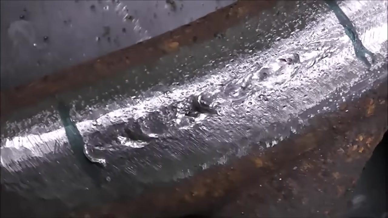
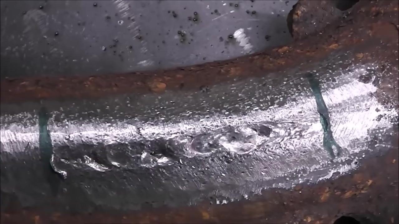
Inspect the completed bead for uniformity, smoothness, and proper fusion to the base metal. A well-executed weld blends smoothly into the surrounding metal.
-
Compare the length of the completed bead to the amount of electrode consumed. In this example, about half of a 3/32" rod was used to complete the weld on the manifold.
-
Confirm the electrode size used for the repair. A 3/32" (2.4 mm) electrode provides a good balance of control and penetration for cast iron welding.
Manage thermal stress with rod selection and preheat
-
Choose a rod with good elongation properties, such as the 77 rod, for parts like exhaust manifolds that undergo repeated heating and cooling cycles. This property helps prevent future cracking as the metal expands and contracts.
-
Account for thermal expansion and contraction in your rod selection. A rod with good elongation ensures the weld can withstand the stresses of thermal cycling without failing.
-
Set the welding machine to approximately 60 amps for optimal performance with the 72 or 77 rods, and adjust slightly if needed for your specific machine or material thickness.
-
Follow the rod manufacturer's recommendations for stringer bead or moderate weave technique. Both techniques are suitable for the 72 and 77 rods.
-
Take advantage of the all-position rating on both rods to weld overhead, vertical, flat, or horizontal without repositioning the part.
-
Limit each bead to 1 inch and allow full cooling before the next pass. Alternate bead placement by starting the next bead at the opposite end of the repair once the previous bead has cooled, then repeat until the weld is complete.
-
Peen each bead immediately after welding, while it is still hot, to relieve internal stresses and help prevent cracking.
-
Weld without preheat if necessary, understanding that this increases the risk of cracking because the cast iron experiences extreme temperature swings from room temperature to welding temperature very quickly.
-
Preheat the part to around 500°F (260°C) when possible to reduce the temperature differential during welding and lower the risk of cracking. With preheat, the part only needs to rise from 500°F to welding temperature rather than from room temperature.
-
Select a rod that allows the weld metal to expand and contract without cracking, such as the 77 rod, especially for parts subject to thermal cycling like exhaust manifolds.
Finish and blend the repair
-
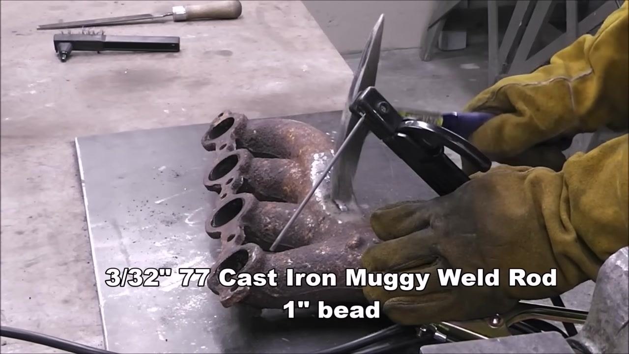
Weld the 1" bead using the 3/32" 77 Cast Iron Muggy Weld rod, wearing protective gloves and keeping a file and wire brush nearby for cleanup. The 72 rod is less forgiving than the 77 rod, so preheating can help optimize results, particularly when using the 72 rod.
-
Continue holding the rod steadily in place against the manifold as you complete the weld. The 77 rod is reliable and consistent, giving no warning indicators before any potential failure.
-
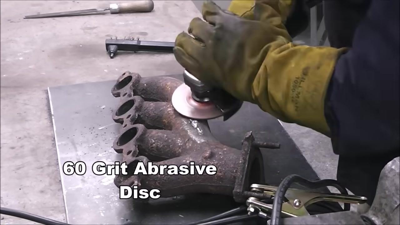
Clean the welded area with a 60-grit abrasive disc on an angle grinder. If desired, preheating before welding further increases your odds of success.
-
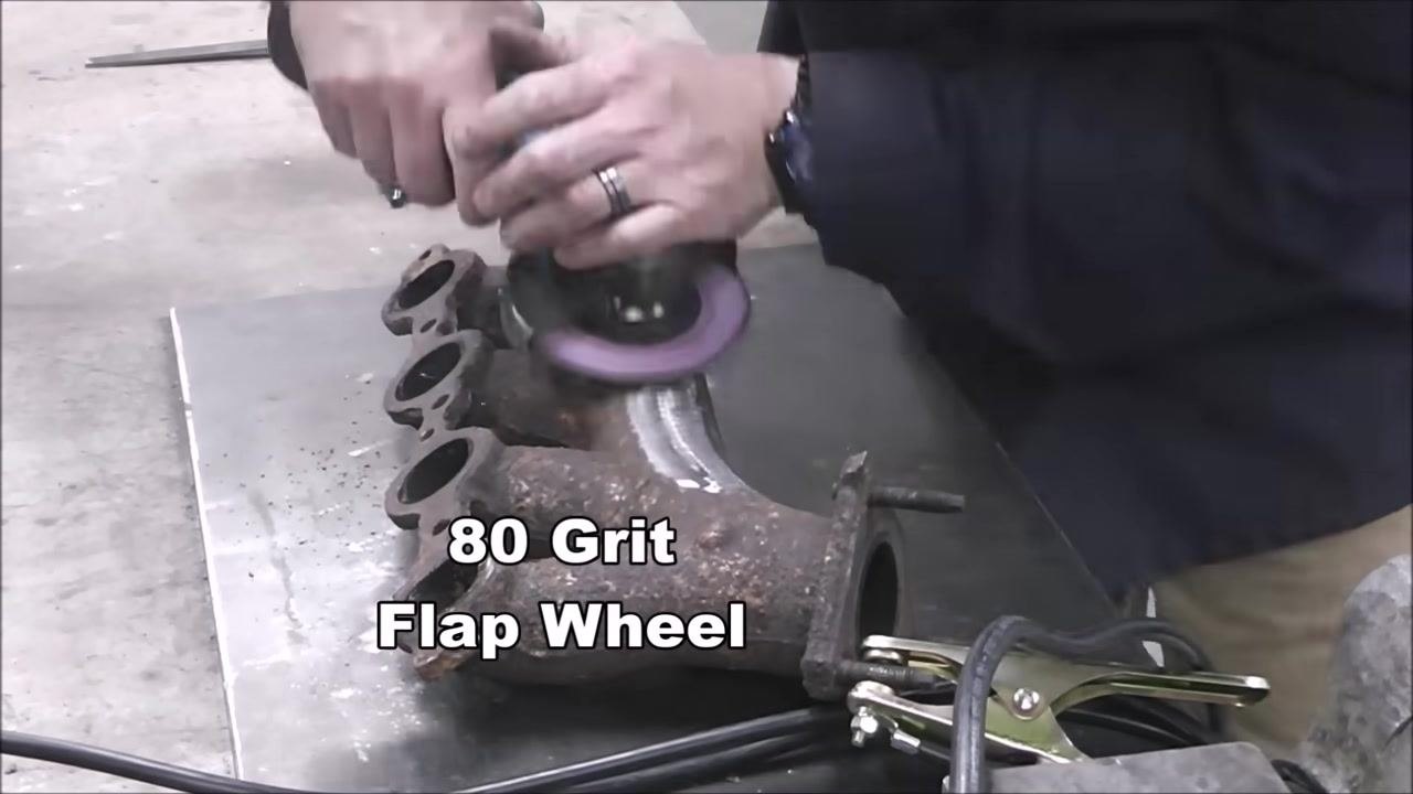
Smooth and blend the repaired area with an 80-grit flap wheel until the repair is finished to a smooth, uniform appearance.
-
Examine the repaired area closely. The weld should blend seamlessly with the original cast iron so the repair is visually indistinguishable from the surrounding metal.
-
Confirm that the repair is perfectly integrated and not visible after finishing. The weld bead should be flush and uniform with the cast iron surface.
-
Review the finished weld at close range to confirm fine finishing marks and an overall smooth surface, verifying a professional result.
Optional preheat and post-heat procedure
If you want additional insurance against cracking, you can apply preheat and post-heat around the weld:
- Use a propane torch to slowly heat the part before welding (preheat).
- Weld the part following the bead, cooling, and peening steps above.
- After welding, let the part cool down slowly (post-heat) to minimize stress and prevent cracking.
This is an alternative to relying solely on rod selection and short-bead technique, and it can be combined with either the 72 or 77 rod.
Verification and summary
Before considering the repair complete, confirm the following:
- The crack was fully traced, drilled at both ends with a 3/16" bit, and grooved along its entire length before welding.
- The correct rod was selected for the part's condition: 72 Cast Iron Weld for dirty or oil-contaminated cast iron, or 77 Cast Iron Weld for maximum crack resistance and machinability.
- The welding machine was set to approximately 60 amps for a 3/32" rod, with adjustments made (such as down to 51 amps) if undercut or excessive heat was observed.
- Each bead was limited to 1 inch, followed by complete cooling and peening while the bead was still hot.
- The finished weld shows no undercut, ridges, or grooves, and blends smoothly with the base metal.
- The repaired area was cleaned with a 60-grit abrasive disc and finished with an 80-grit flap wheel until the repair is visually indistinguishable from the surrounding metal.
- Preheat to approximately 500°F (260°C) and slow post-heat cooling were applied where extra crack resistance was needed.
Welding cast iron does not require specialized equipment beyond a stick welder, the correct Muggy Weld rod, and careful attention to heat control. Following these steps — proper preparation, correct rod selection, short controlled beads, peening, and slow cooling — produces a durable, crack-resistant repair that blends seamlessly into the original part.


Generation details: cost, quality tiers
Docsie billed 6,500 credits ($4.55) to analyze this 13-minute video at standard quality. The rewrite, template fill and Word/PDF exports were included. The same video at each quality tier:
| Quality | Frames sampled | Credits | Approx. cost |
|---|---|---|---|
| Draft | every 16-30 s | 3,250 | $2.27 |
| Standard (this guide) | every 8-15 s | 6,500 | $4.55 |
| Detailed | every 4-7 s | 13,000 | $9.10 |
| Ultra | every 1-3 s | 26,000 | $18.20 |
Credits priced at $0.70 per 1,000; plans include a monthly allowance. Enterprise customers on on-premise or bring-your-own-model deployments run this on their own inference and pay no per-video credits.
Generated by Docsie Video-to-Docs on 2026-09-14 from a 12-minute video. Screenshots are frames from the source video and belong to their creator, Brandon Lund, whose original is embedded above. If you own this video and want the guide removed or credited differently, contact us and we will act within one business day.