
How to Use a Milling Machine
This document explains how to use a milling machine to machine a rectangular metal billet from raw stock through facing, drilling, tapping, and finishing operations. It walks through securing the workpiece, referencing technical drawings, operating the spindle and cutters, and inspecting the finished part. Follow each step in sequence and confirm your setup against the technical drawings before advancing to the next operation.
Video: Milling machine - Easy job by Marek Tabi (2022). All credit for the demonstration goes to the creator; watch the original on YouTube. The written guide below was generated from this video by Docsie. Creator? Request a change or removal.
This document explains how to use a milling machine to machine a rectangular metal billet from raw stock through facing, drilling, tapping, and finishing operations. It walks through securing the workpiece, referencing technical drawings, operating the spindle and cutters, and inspecting the finished part. Follow each step in sequence and confirm your setup against the technical drawings before advancing to the next operation.
Purpose
This SOP provides a standardized procedure for operating a milling machine to produce a machined metal part with multiple drilled and tapped holes, milled edges, and faced surfaces, in accordance with technical drawing specifications.
Scope
This procedure covers the full machining sequence for a rectangular metal billet, including initial setup, face milling, hole drilling, edge milling, tapping, and final inspection. It applies to operators working with a vertical milling machine and standard hand tools.
Required equipment and materials
- Milling machine with vise, spindle, and handwheels
- Raw metal billets (rectangular stock) matching the technical drawing specifications
- Technical drawings with dimensions, hole locations, and section views
- Face mill cutter
- End mill cutter
- Center drill
- Twist drill bits
- Chamfering or deburring tool
- Tap and tap wrench
- Calipers or other measuring tools
- Blue marker or pen for annotating drawings
- Cutting fluid
- Rags for cleanup
Safety precautions
- Always follow proper safety procedures when operating milling machines.
- Wear eye protection at all times during machining operations.
- Keep hands and fingers clear of moving parts, including the drill bit's path.
- Wear appropriate safety gear when operating the handwheel and feed controls.
- Use cutting fluid when tapping threads, and clean the tap regularly to prevent chip buildup.
- Refer to technical drawings frequently to confirm that each machining step is performed accurately.
Procedure
Section 1: Preparing and machining the workpiece
Step 1: Review the technical drawings and gather materials
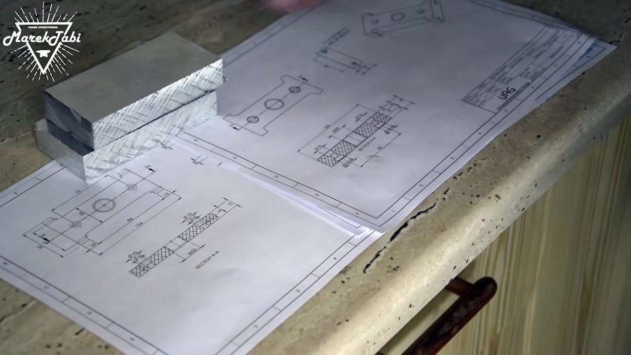
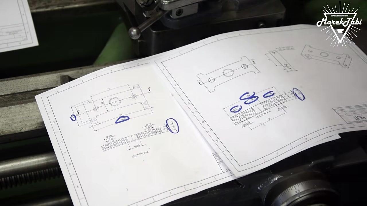
Lay out the technical drawings on a flat work surface so that all dimensions and features are clearly visible. Place the raw metal billets next to the drawings for reference. Confirm that the drawings specify all necessary measurements, hole locations, and section views, and verify that you have the correct number and size of billets.
Step 2: Secure the workpiece in the milling machine
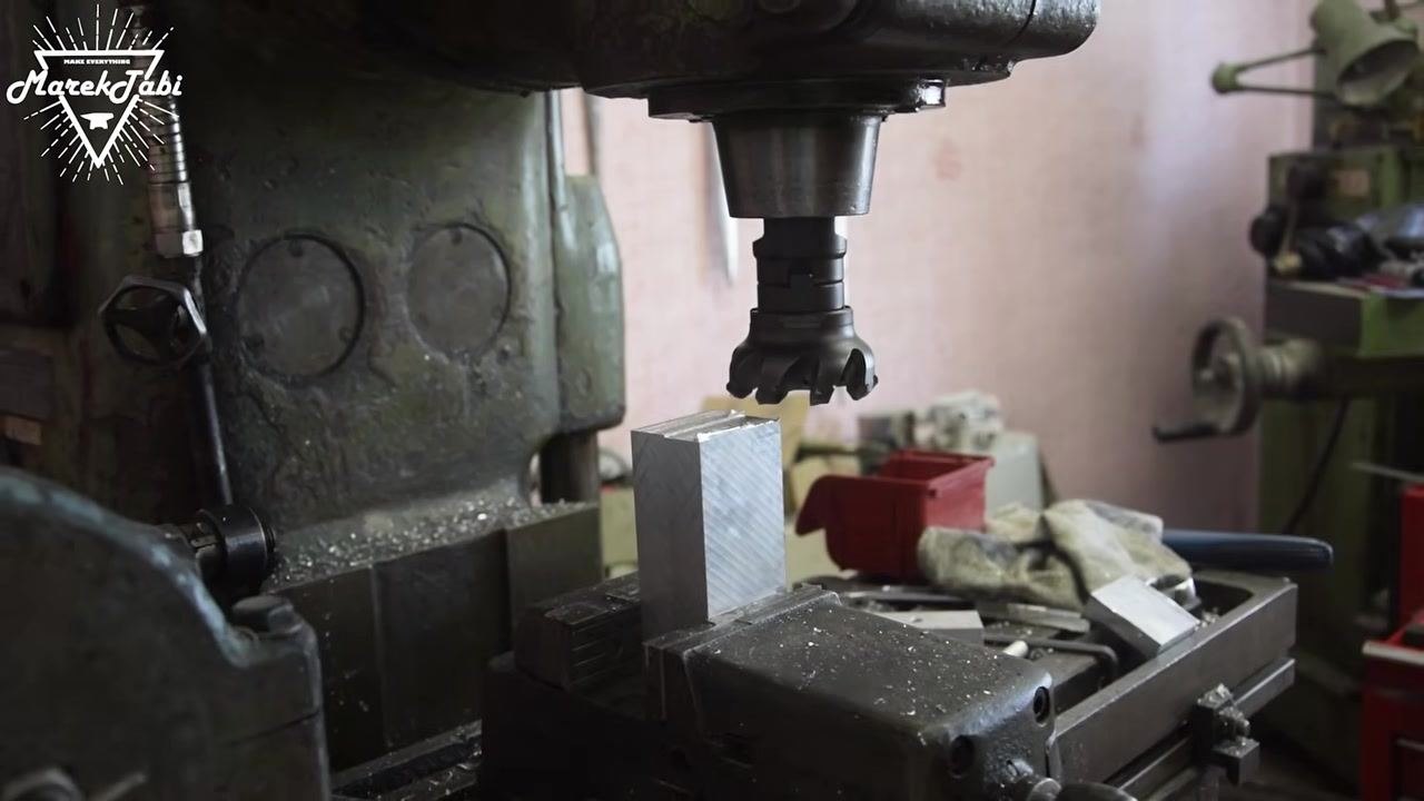
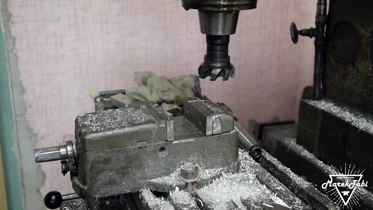
Place one billet vertically in the machine vise, ensuring it is firmly clamped and aligned. Position the billet so the surface to be machined is accessible to the milling cutter. Confirm the machine is clean and free of debris around the vise area, then prepare the milling cutter in the spindle above the workpiece.
Step 3: Install and adjust the milling cutter
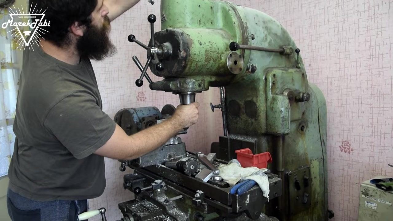
Use the machine's handles and controls to adjust the spindle and cutter position. Ensure the correct cutter is installed for the intended operation, such as facing, slotting, or drilling. Tighten the spindle, verify the cutter is securely mounted, and double-check its alignment with the workpiece.
Step 4: Prepare for machining
Confirm that the correct cutter is installed, such as a face mill for surfacing. Ensure the work area is clear of unnecessary tools and debris, then position the cutter just above the billet, ready for the machining operation.
Step 5: Align the cutter and workpiece
Move the billet into precise alignment under the cutter using the machine's handwheels. Double-check the position to ensure the cutter will contact the correct surface before beginning the machining operation.
Step 6: Measure and mark the workpiece
Use calipers or a measuring tool to verify the billet's dimensions and alignment. Mark the billet or reference the drawing to ensure correct machining locations, and remove any chips or debris from the work area before proceeding.
Step 7: Begin machining the surface
Lower the face mill cutter to make contact with the billet's surface and start the milling operation. Ensure the cutter moves smoothly across the billet, and monitor the process to achieve a flat, even surface as specified in the drawings.
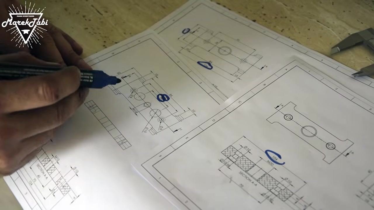
Step 8: Reference and mark the technical drawings
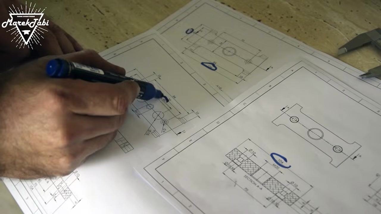
Use a marker to highlight or circle key features and dimensions on the technical drawings. Clearly indicate which holes or surfaces are to be machined next, and double-check all marked features against the billet for accuracy.
Step 9: Continue marking and planning
Continue marking all relevant features on the technical drawings. Ensure all machining steps are planned and clearly indicated before proceeding, and keep the drawings nearby for constant reference during machining.
Step 10: Prepare for drilling operations
Return to the milling machine and ensure the billet is still securely clamped. Prepare the spindle for the next operation, such as drilling holes as indicated in the drawings, and use the machine's controls to position the workpiece for drilling.
Section 2: Drilling and inspecting holes in the workpiece
Step 1: Align the center drill with the marked position
Lean in closely to visually align the center drill with the marked location on the billet. Ensure the billet remains securely clamped in the vise and that the surface is marked with blue ink showing hole locations and directional arrows. The spindle should be fitted with a center drill positioned precisely above the marked spot.
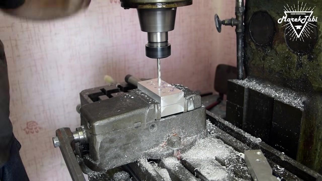
Step 2: Drill the pilot hole
Switch to a twist drill bit in the spindle. Begin drilling at the marked location, ensuring the drill bit is perpendicular to the billet surface. Observe the formation of metal chips and the swirling motion of the drill as it penetrates the billet, and maintain a steady feed rate to avoid damaging the drill bit or workpiece.
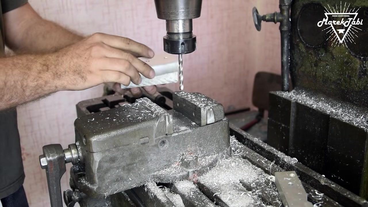
Step 3: Continue drilling to full depth
Allow the drill bit to reach the required depth as specified in the technical drawings. Monitor the drilling process to ensure the hole is clean and accurately positioned. The billet remains clamped in the vise, with metal shavings scattered around the work area.
Step 4: Remove the workpiece from the vise
Stop the machine and carefully unclamp the billet from the vise. Use both hands to lift the billet, taking care to avoid sharp edges and hot surfaces, and inspect the drilled hole for cleanliness and correct placement.
Step 5: Drill additional holes as marked
Re-clamp the billet in the vise if necessary, aligning the next marked position under the drill bit. Drill additional holes at the locations indicated by the blue ink markings and arrows, ensuring each hole is drilled to the correct diameter and depth as specified in the drawings.
Step 6: Complete drilling all required holes
Continue drilling until all marked holes are completed. Inspect each hole for proper size, depth, and placement, confirming that all required holes have been drilled with visible blue ink markings and metal shavings around the work area.
Step 7: Inspect and clean the workpiece
Remove the billet from the vise after all drilling operations are complete. Brush off excess metal shavings and inspect the holes for burrs or irregularities, confirming the billet matches the technical drawing specifications.

Step 8: Reference and update technical drawings
Return to the technical drawings and use a blue marker to circle or highlight the completed holes and features. Double-check all dimensions and hole locations against the machined billet, and mark off each completed operation to track progress.
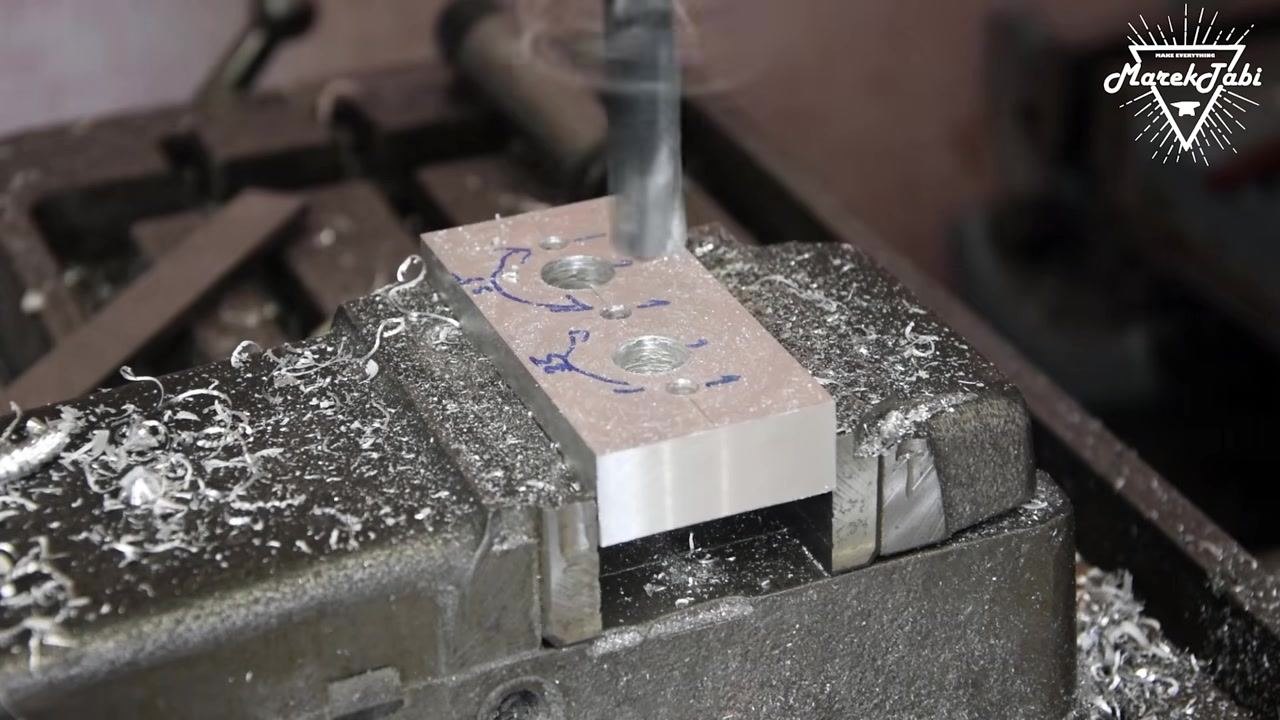
Step 9: Verify all features are accounted for
Review the technical drawings to confirm that all required holes and features have been machined. Ensure all circled features correspond to the completed work on the billet, and keep the drawings accessible for the next machining steps or inspection.
Section 3: Squaring and milling the workpiece
Step 1: Secure the workpiece in the vise
Place the machined billet back into the milling machine vise with a flat face upward, tightly clamped between the vise jaws. Confirm the billet is free of debris and sits flush against the vise bed. Some metal shavings may remain from previous operations.
Step 2: Measure the workpiece with calipers
Remove the billet from the vise and use calipers to check its dimensions. Measure the width or thickness as required by the technical drawing, and compare the measured value to the specified dimensions before further machining.
Step 3: Prepare for face milling
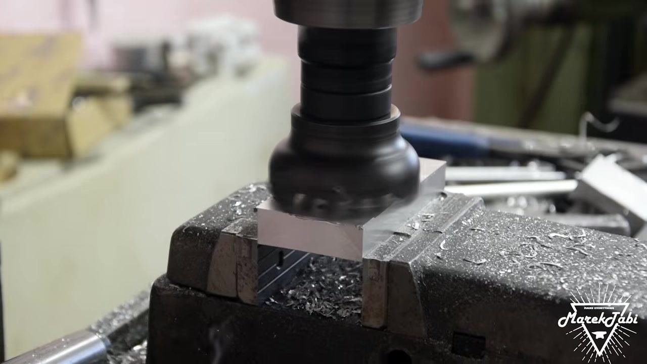
Place the billet back into the vise, ensuring it is properly aligned for the next milling operation. Confirm the face mill cutter is installed in the spindle and positioned above the billet, and clear the vise area of obstructions.
Step 4: Perform the face milling operation
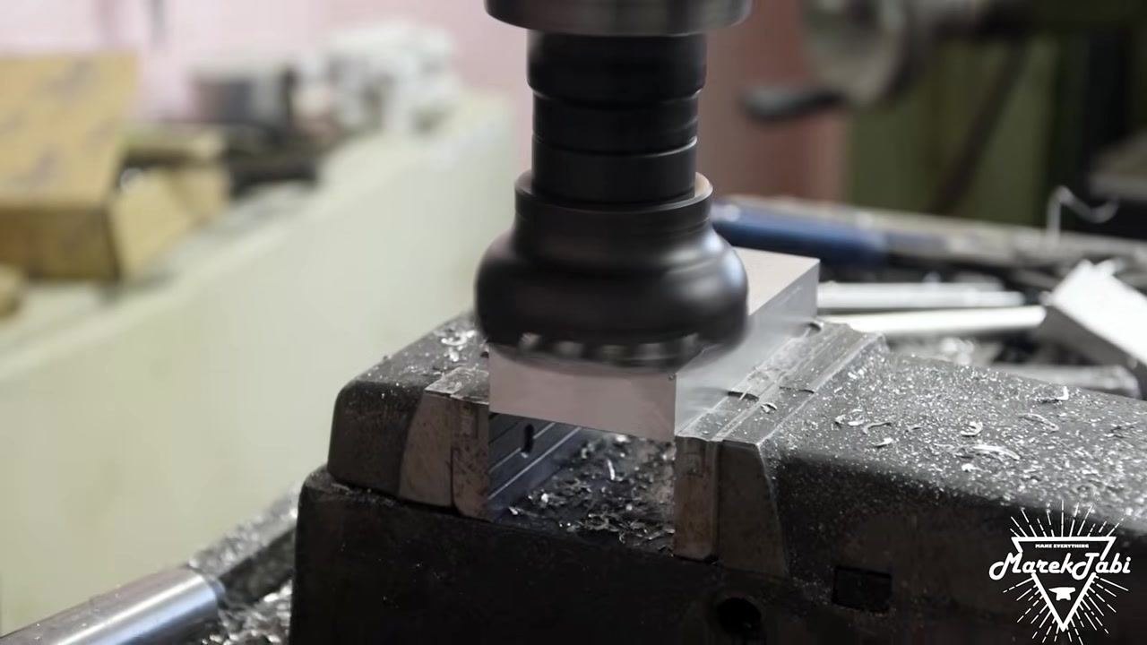
Start the milling machine and lower the face mill cutter onto the billet surface. Move the cutter across the billet to create a smooth, flat surface, maintaining a steady feed rate and keeping the cutter perpendicular to the billet.
Step 5: Continue face milling to achieve desired flatness
Make additional passes with the face mill cutter as needed to achieve the required flatness and surface finish. Monitor progress for uniform material removal, and stop the machine once the desired finish is achieved.
Step 6: Repeat face milling on adjacent surfaces
Rotate or reposition the billet in the vise to expose another surface for face milling. Repeat the process to ensure all relevant faces are flat and parallel as specified in the technical drawing, then remove any burrs or sharp edges after milling.
Section 4: Verifying machined features and preparing for further operations
Step 7: Review technical drawings for next steps
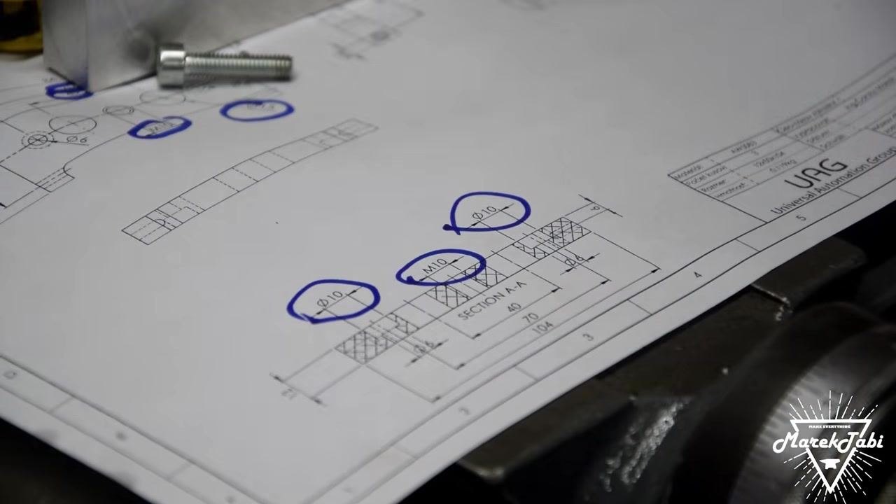
Place the billet and a fastener on the technical drawing for reference. Examine the drawing to identify the next features to be machined, such as holes or threads, noting that key dimensions and hole locations are circled in blue marker. Confirm the drawing matches the current state of the billet.
Step 8: Mill additional features, such as slots or counterbores
Secure the billet in the vise and position the end mill above the area to be machined. Begin milling the specified feature at the marked location, ensuring the end mill is properly aligned and the billet is firmly clamped. Monitor the process to achieve the correct depth and dimensions.
Step 9: Chamfer or deburr machined holes
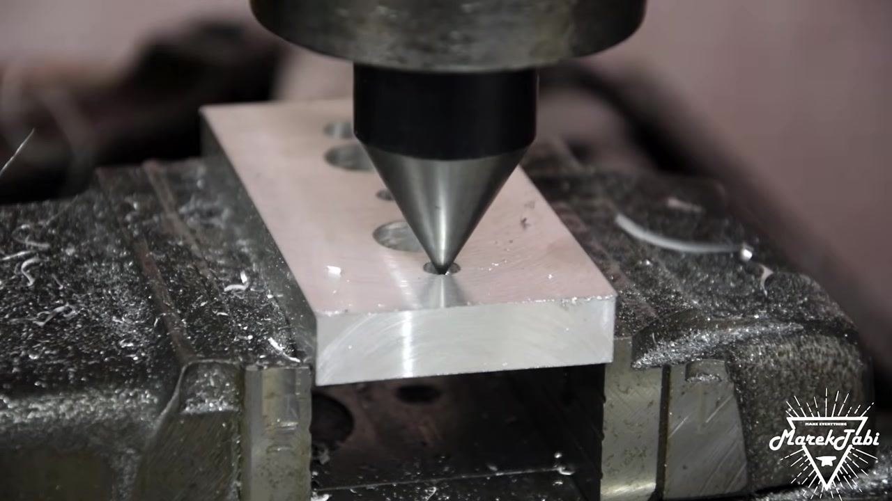
Switch to a chamfering or deburring tool in the spindle. Lower the tool into each drilled hole to remove sharp edges and create a clean chamfer. Ensure all holes are free of burrs and inspect the billet for remaining debris or imperfections.
Section 5: Machining the opposite side of the workpiece
Step 1: Align the center drill on the opposite side
Place the machined metal workpiece securely in the vise with the face containing pre-drilled holes facing upward. Position the center drill precisely above the center mark of the opposite side, and confirm the alignment visually before proceeding.
Step 2: Drill the center hole
Switch to a twist drill bit in the spindle and lower it into the marked center hole. Begin drilling, ensuring the bit is perpendicular to the surface for an accurate hole, and monitor the process while clearing away accumulating chips.
Step 3: Consult the technical drawing
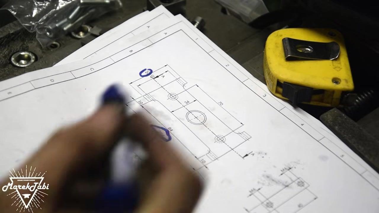
Pause machining and refer to the technical drawing for dimensional verification. Review hole locations, diameters, and other critical measurements, using a pen to circle or mark completed features as needed. Keep the drawing nearby for ongoing reference.
Step 4: Mill the edge of the workpiece
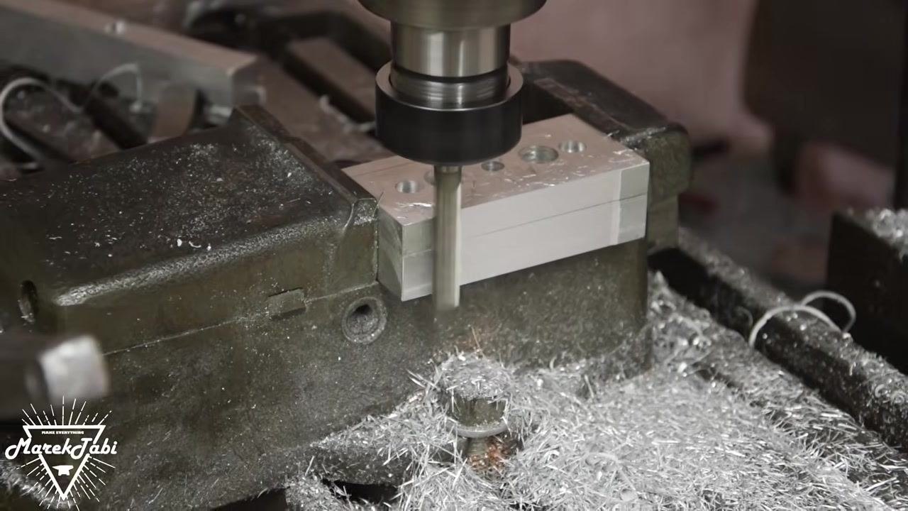
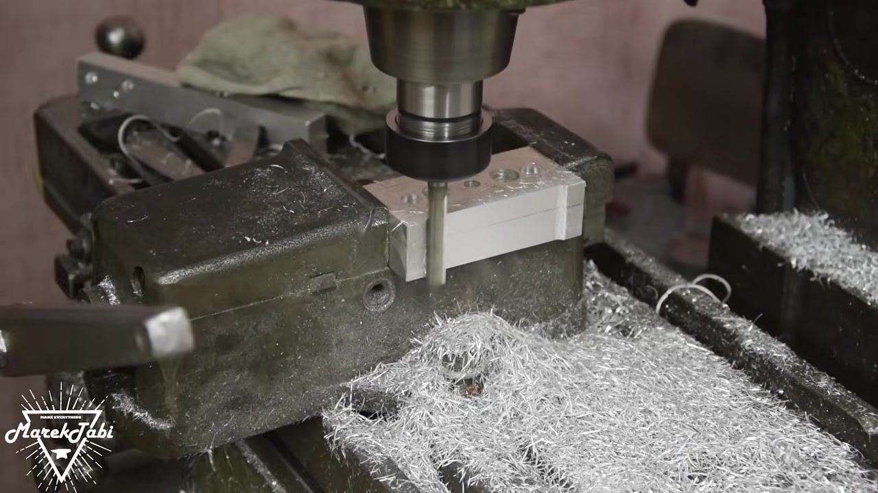
Reposition the workpiece in the vise if necessary to expose the edge for milling. Use an end mill to machine the edge, ensuring a smooth and even finish, and remove excess material as specified in the technical drawing while maintaining a steady feed rate.
Step 5: Continue edge milling
Progressively move the end mill along the length of the workpiece edge. Ensure the entire edge is uniformly milled according to the drawing specifications, checking for consistent surface finish and dimensional accuracy.
Step 6: Operate the milling machine feed
Use the handwheel to advance the workpiece under the milling cutter, adjusting the feed rate as needed for optimal cutting and surface finish. Keep hands clear of moving parts and wear appropriate safety gear. Observe the progress and stop the machine when the cut is complete.
Step 7: Perform the final edge milling pass
Make a final pass with the end mill to achieve the desired surface finish and dimensions. Inspect the workpiece for any remaining rough spots or burrs, then remove it from the vise once milling is complete.
Step 8: Review and mark the technical drawing
Refer back to the technical drawing to verify all machining steps are complete. Mark off completed features and dimensions with a pen, and double-check all measurements and features against the drawing.
Step 9: Inspect the work area and finished part
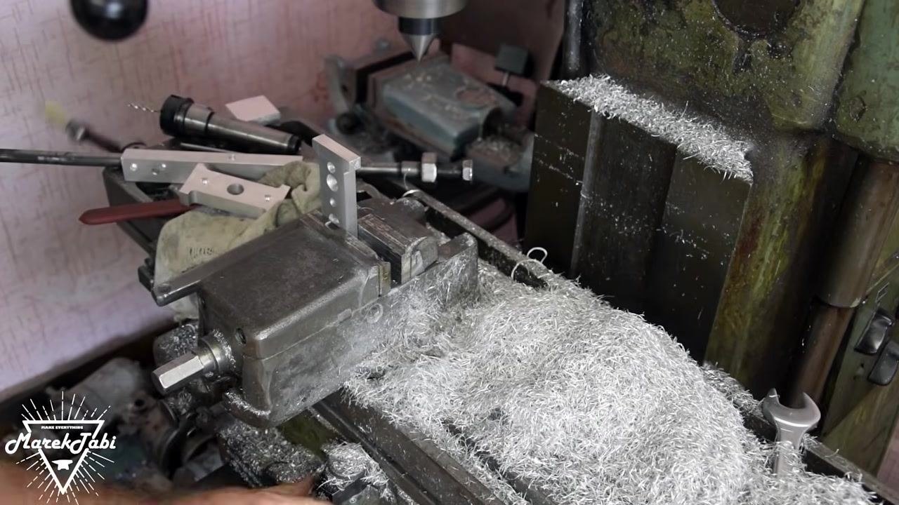
Survey the work area for cleanliness and organization. Inspect the finished workpiece for accuracy, surface finish, and completeness, ensuring all tools and parts are accounted for and returned to their proper places.
Step 10: Prepare for the next operation or cleanup
Leave the workpiece in the vise if further operations are required, or remove it if finished. Begin cleaning up metal shavings and organizing tools for the next task.
Section 6: Drilling and tapping holes in the machined workpiece
Step 1: Position the workpiece for drilling
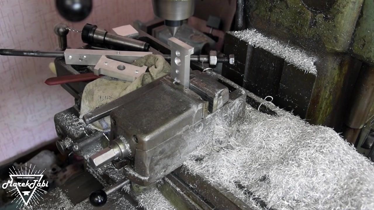
Place the machined metal workpiece vertically in the vise with the face to be drilled facing upward and securely clamped. Align the drill bit above the marked hole location, and confirm the setup is stable and perpendicular to the surface.
Step 2: Secure the workpiece by hand
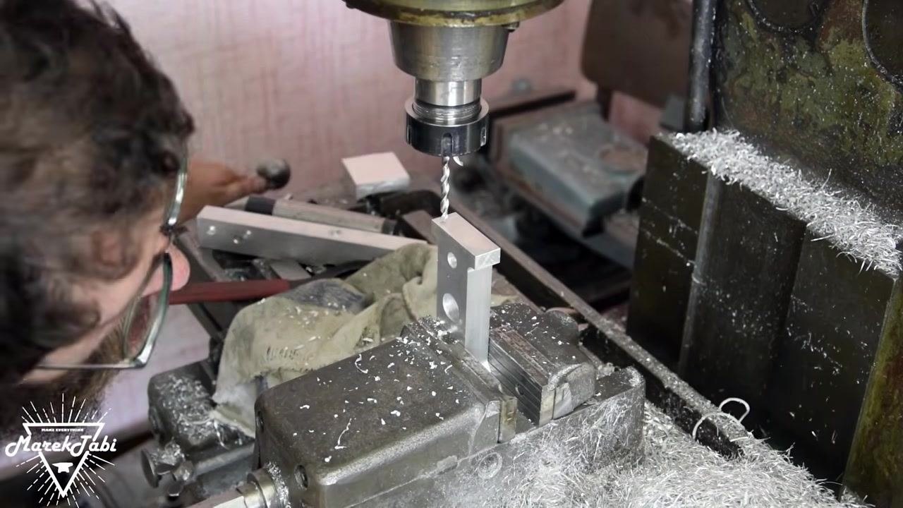
Hold the workpiece steady with one hand while making final adjustments to its position. Double-check that the drill bit is centered over the intended hole location, and keep fingers clear of the drill bit's path.
Step 3: Final alignment before drilling
Use your hand to make precise adjustments to the workpiece's position in the vise. Ensure the workpiece is flush and properly aligned for accurate drilling.
Step 4: Begin tapping the drilled hole
Insert a tap into the newly drilled hole to cut internal threads. Use a tap wrench to start threading by hand, ensuring the tap is perpendicular to the surface, and apply gentle, even pressure to avoid cross-threading.
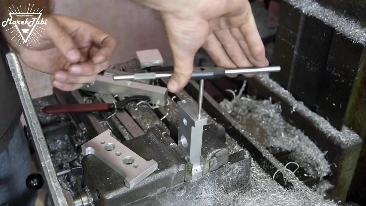
Step 5: Manually cut threads with the tap wrench
Rotate the tap wrench clockwise to cut threads into the hole. Periodically reverse the tap slightly to break chips and prevent binding, continuing until the desired depth is reached.
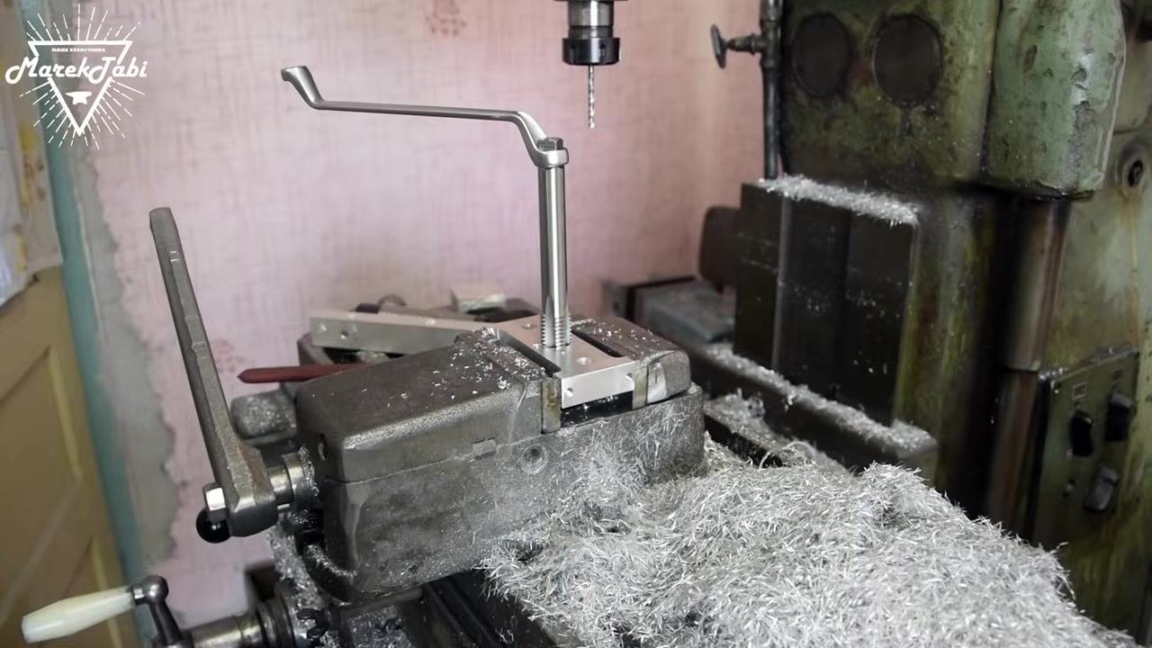
Step 6: Continue tapping to full depth
Use the tap wrench to continue threading the hole to its full depth. Maintain a steady, controlled motion to ensure clean threads, then remove the tap once threading is complete.
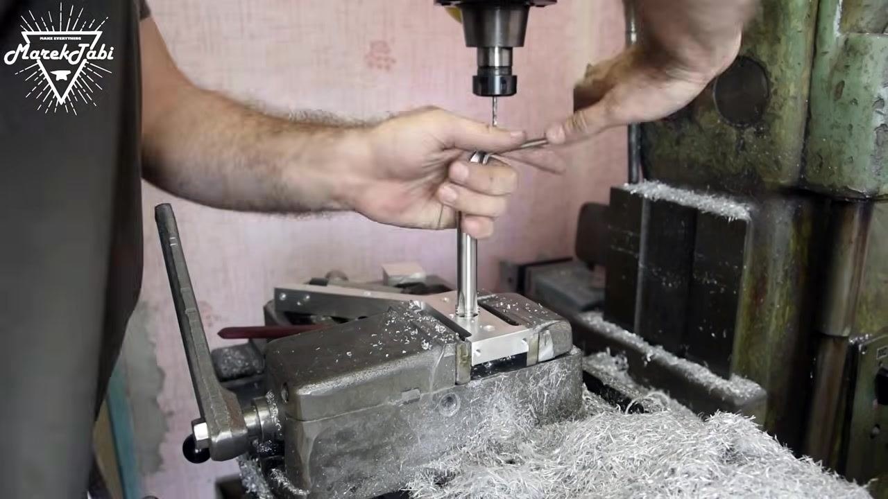
Step 7: Complete the tapping process
Finish threading the hole and carefully remove the tap from the workpiece. Inspect the threads for cleanliness and accuracy.
Step 8: Inspect the finished workpiece
Remove the workpiece from the vise. Hold the workpiece up and visually inspect the drilled and tapped holes for quality, comparing the finished part to the technical drawing to verify all features are present and correctly machined.
Step 9: Compare and verify multiple parts
Place two finished workpieces side by side for comparison. Check that all holes, threads, and machined features match between parts, confirming that both meet the required specifications and tolerances.
Verification and final inspection
Once all operations are complete, verify the finished workpiece against the technical drawings at each stage: confirm that all faces have been faced and squared, all holes are drilled to the correct diameter and depth, all threads are cut cleanly, and all edges are chamfered or deburred. Compare multiple parts side by side to confirm consistency across holes, threads, and machined features, and inspect all surfaces for burrs or defects before final assembly or use.
What's next
After confirming that the workpiece matches the technical drawing specifications and passes inspection, proceed to final assembly or the next stage of production. Clean the work area, return tools to their proper storage locations, and apply cutting fluid maintenance to the tap and other tooling before the next milling machine operation.
Generation details: cost, quality tiers
Docsie billed 4,500 credits ($3.15) to analyze this 9-minute video at standard quality. The rewrite, template fill and Word/PDF exports were included. The same video at each quality tier:
| Quality | Frames sampled | Credits | Approx. cost |
|---|---|---|---|
| Draft | every 16-30 s | 2,250 | $1.57 |
| Standard (this guide) | every 8-15 s | 4,500 | $3.15 |
| Detailed | every 4-7 s | 9,000 | $6.30 |
| Ultra | every 1-3 s | 18,000 | $12.60 |
Credits priced at $0.70 per 1,000; plans include a monthly allowance. Enterprise customers on on-premise or bring-your-own-model deployments run this on their own inference and pay no per-video credits.
Generated by Docsie Video-to-Docs on 2026-09-14 from a 8-minute video. Screenshots are frames from the source video and belong to their creator, Marek Tabi, whose original is embedded above. If you own this video and want the guide removed or credited differently, contact us and we will act within one business day.