
How to Use a Cmm Machine
This document explains how to use a CMM machine to measure and verify the geometric features of manufactured parts. A Coordinate Measuring Machine (CMM) is a device used to measure and report geometric features of manufactured parts, including circles, lines, squares, and geometric dimensioning and tolerancing (GD&T) parameters such as angularity and circularity. Understanding how a CMM operates, the coordinate systems it uses, and where it is applied will help you interpret CMM output correctly and recognize why it is preferred over conventional metrology methods.
Video: What is a CMM? || THORS Coordinate Measuring Machine (CMM) Basics Course Preview by THORS eLearning Solutions (2023). All credit for the demonstration goes to the creator; watch the original on YouTube. The written guide below was generated from this video by Docsie. Creator? Request a change or removal.
This document explains how to use a CMM machine to measure and verify the geometric features of manufactured parts. A Coordinate Measuring Machine (CMM) is a device used to measure and report geometric features of manufactured parts, including circles, lines, squares, and geometric dimensioning and tolerancing (GD&T) parameters such as angularity and circularity. Understanding how a CMM operates, the coordinate systems it uses, and where it is applied will help you interpret CMM output correctly and recognize why it is preferred over conventional metrology methods.
Purpose
The purpose of this procedure is to provide a foundational understanding of what a Coordinate Measuring Machine is, how it captures and processes measurement data, and how its results are used to confirm that a manufactured part matches its intended design and functional purpose.
Scope
This guide applies to anyone who needs to understand the operating principles of a CMM before working with one, including personnel in aerospace, automotive, healthcare, pharmaceutical, and food processing environments where CMMs are used for quality control and inspection.
Required equipment
- Coordinate Measuring Machine (CMM) with a probe
- Connected computer system running CMM software
- Manufactured part to be measured
- Engineering drawing with reference dimensions for comparison
- Protective clothing, where required by the facility's hygiene standards (common in food processing, pharmaceutical, and healthcare settings)
Step-by-step procedure
Step 1: Identify the CMM and its function
Locate the CMM unit and confirm it consists of a probe and a connected computer system. The CMM's role is to measure and report geometric data from the part under inspection.
Step 2: Identify the geometric features to be measured
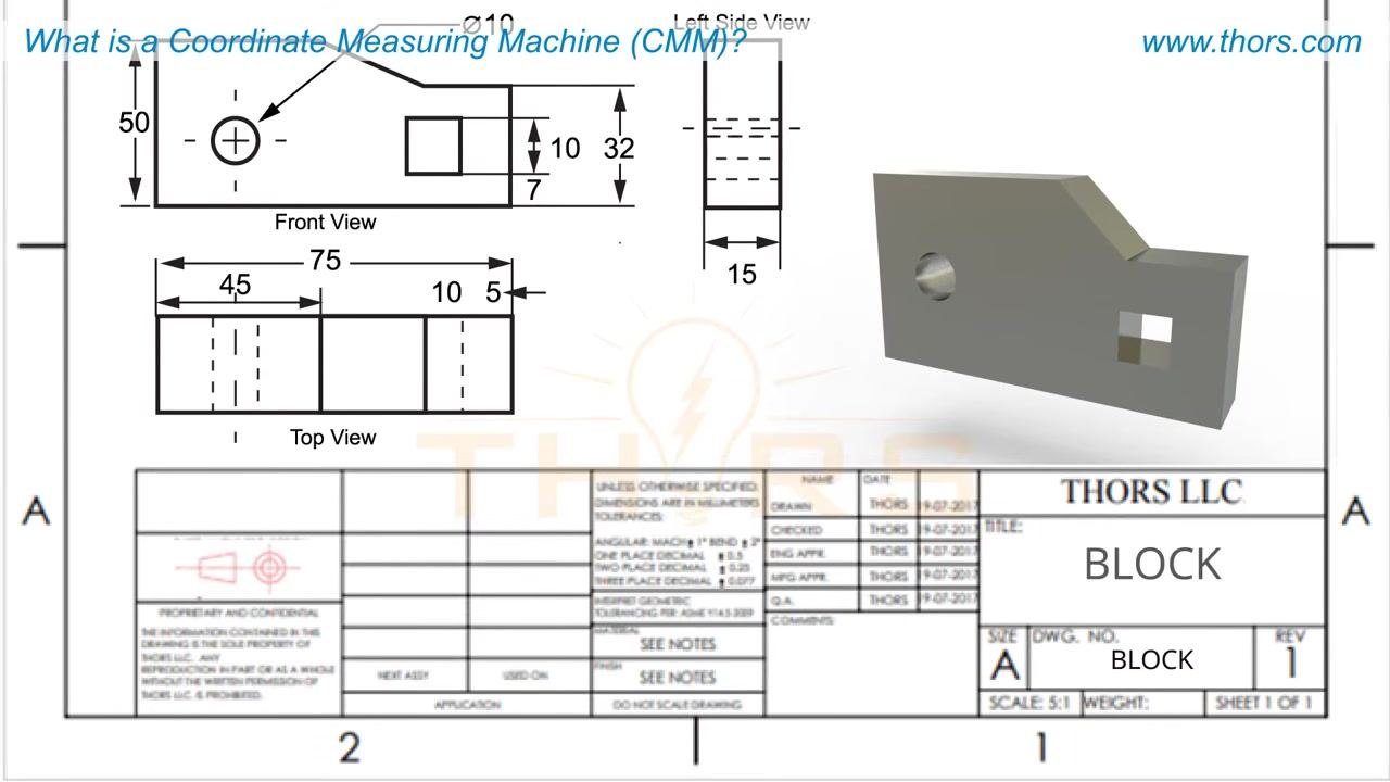
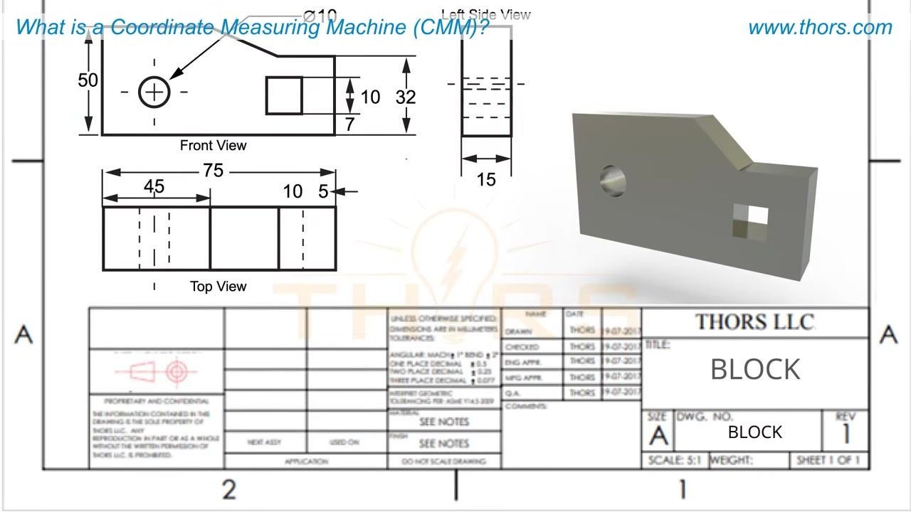
Before measuring, identify which geometric features on the part need verification, such as lines, circles, squares, circularity, and angularity. The quality of a manufactured part depends on how closely these features match the intended design.
Step 3: Compare the part to its engineering drawing
Reference the engineering drawing alongside the physical part. The CMM's measurements will be compared against these design specifications to confirm the part meets its functional requirements.
Step 4: Establish the coordinate system relative to the part
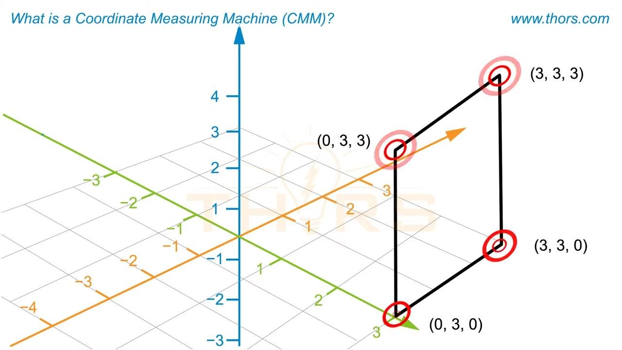
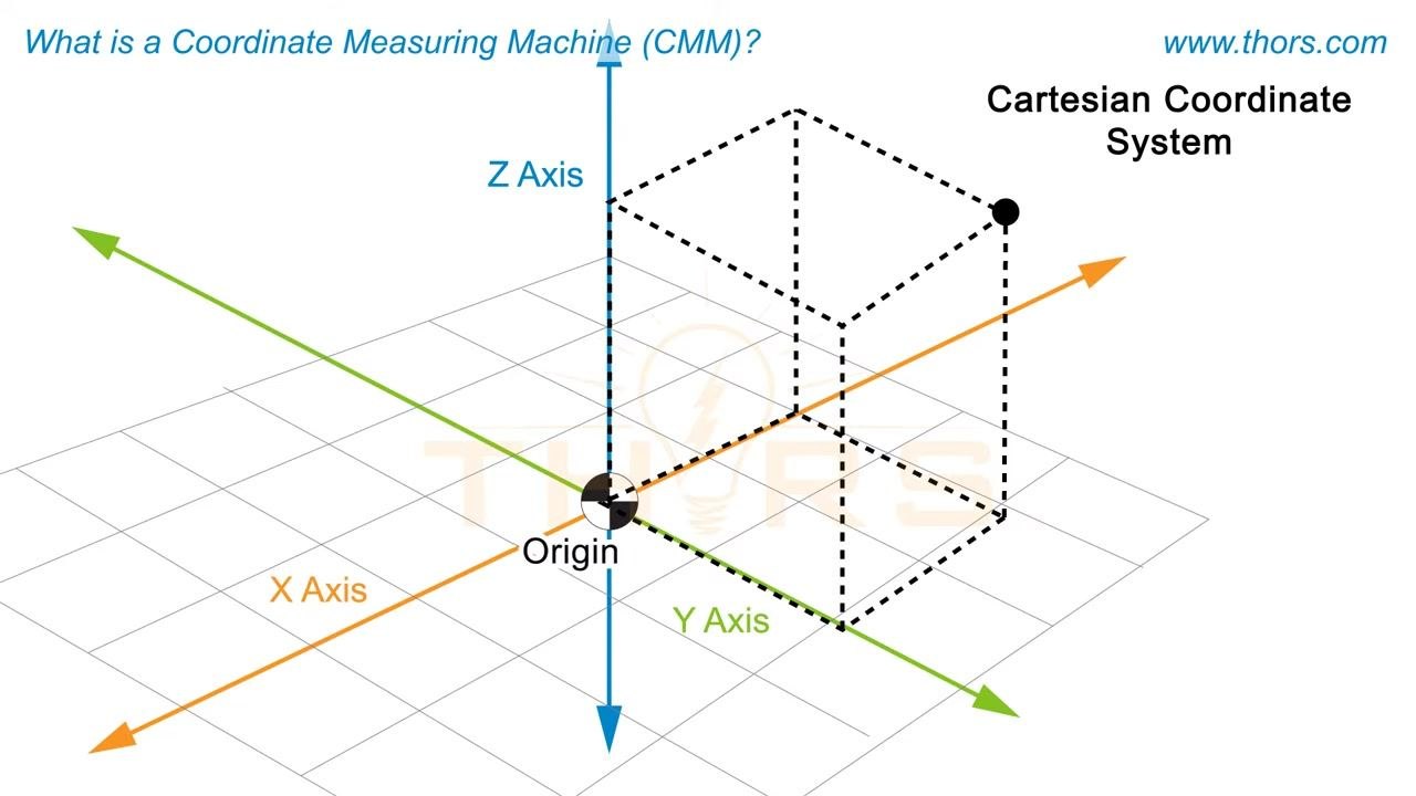
Confirm the origin point (0, 0, 0) on the part and understand how points are defined by three values (X, Y, Z) relative to that origin in three-dimensional space.
Step 5: Perform probing
Move the CMM's probe along the X, Y, and Z axes so it contacts the part at specific locations. This process of collecting point coordinates is called probing.
Step 6: Review the software's feature tracing
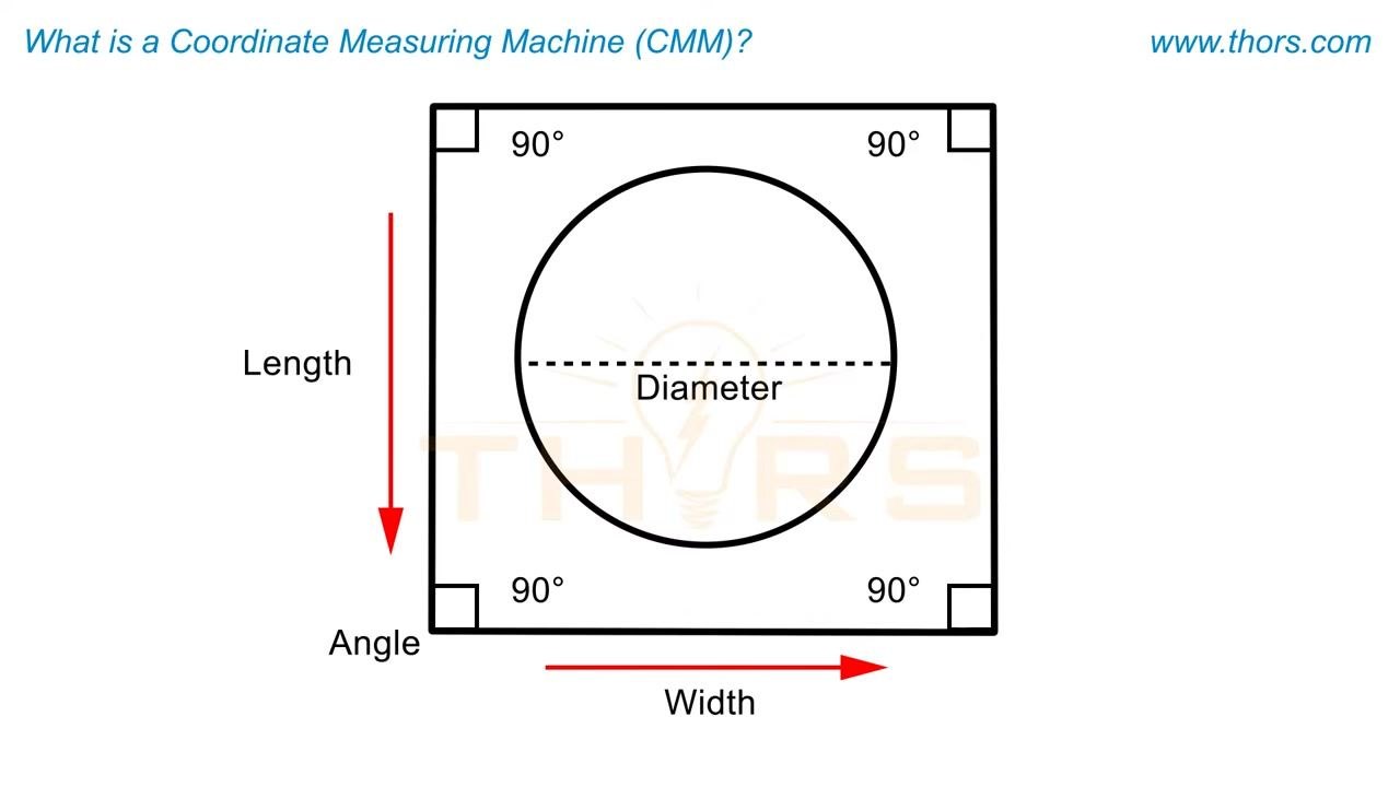
Allow the CMM software to convert the coordinates obtained from probing into geometric features using mathematical formulas. The software traces characteristics such as length, width, angle, and diameter by connecting the measured points.
Step 7: Review feature relationships
Use the software to establish relationships between two or more features by measuring the distance and angle between them. Confirm calculated values for length, width, angle, and diameter, and verify that corner angles match the expected 90° specification where applicable.
Step 8: Understand the Cartesian coordinate system
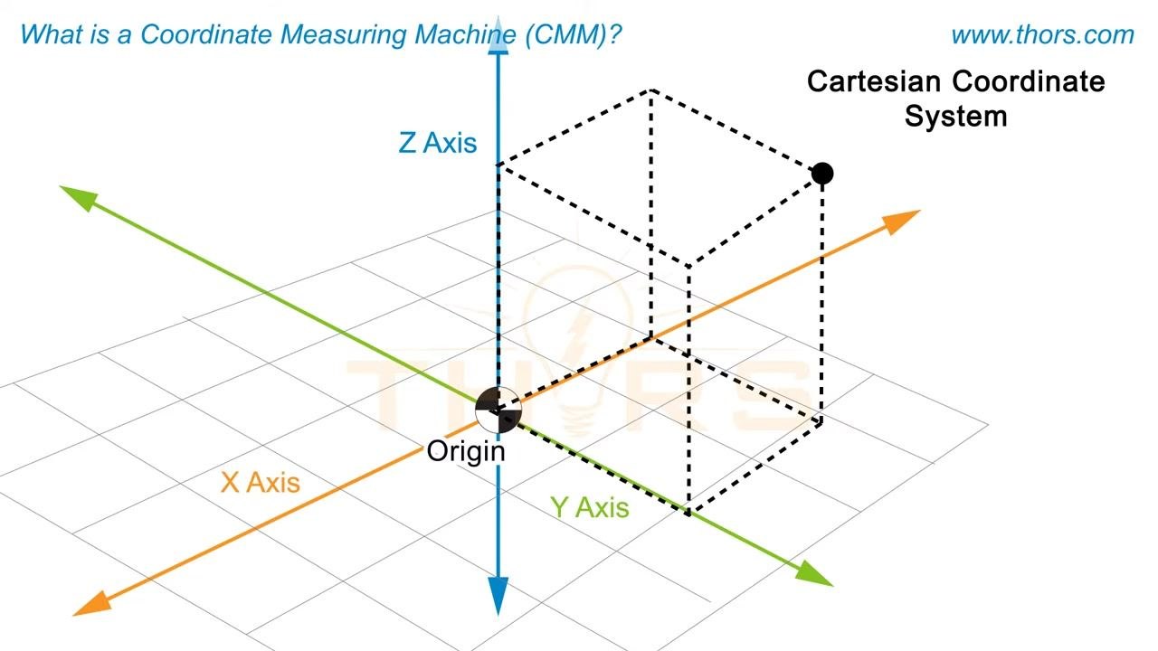
Recognize that the CMM can measure using the Cartesian coordinate system, which defines a point by its distance from the origin along the X, Y, and Z axes.
Step 9: Understand the cylindrical coordinate system
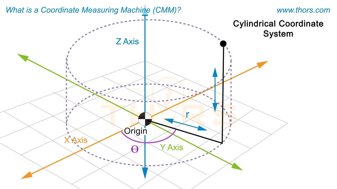
Recognize that a point can also be defined using the cylindrical coordinate system, based on the radial distance (r) from the origin, the angle (θ) made with the horizontal axis, and the distance along the Z-axis.
Step 10: Understand the spherical coordinate system
Recognize that a point can also be defined using the spherical coordinate system, based on the radial distance (r), the angle (θ) made with the vertical axis, and the angle (φ) made with the horizontal axis. The CMM can convert coordinates between the Cartesian, cylindrical, and spherical systems, providing flexibility in measurement and analysis.
Step 11: Compare CMM measurement to conventional metrology
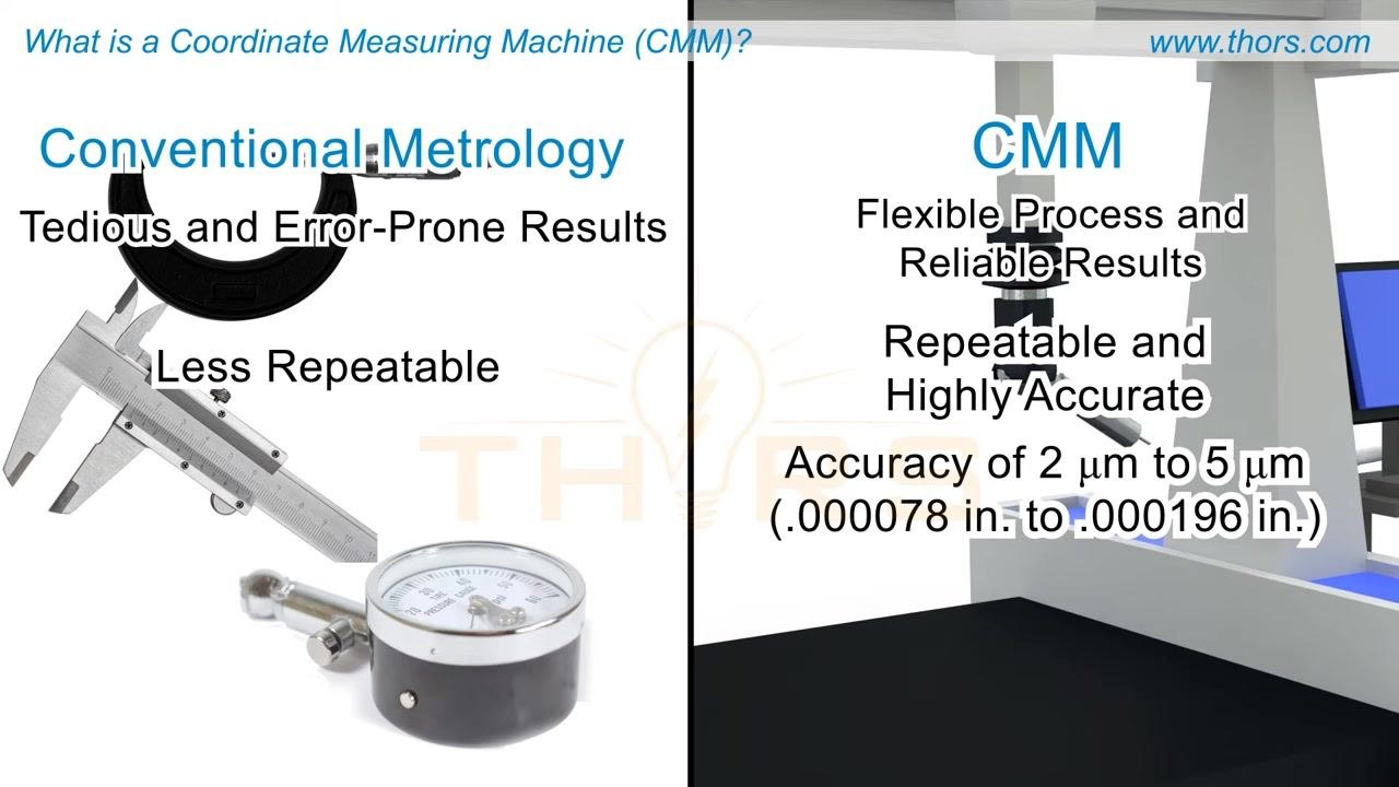
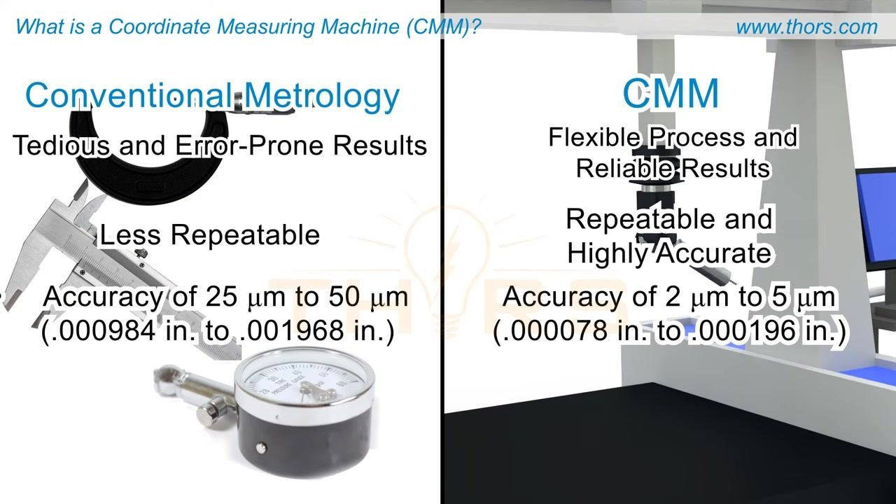
Note that conventional metrology requires different instruments, such as calipers, micrometers, and dial gauges, for different measurements, which makes the process tedious and error-prone. A CMM provides a flexible process with a single device.
Step 12: Compare repeatability
Note that conventional metrology is less repeatable, while CMM measurements are repeatable and highly accurate due to their automated, software-driven process.
Step 13: Verify accuracy ranges
Confirm the expected accuracy for your equipment. A typical 1-meter bridge-type CMM offers an accuracy range of 2 microns to 5 microns (0.000078 in. to 0.000196 in.), compared to 25 microns to 50 microns for conventional metrology.
Step 14: Observe the industrial application environment
Note that CMMs are used across industries including aerospace, automotive, healthcare, pharmaceuticals, and food processing, where they provide precise, repeatable measurements and automate quality control. In such environments, a conveyor system, automated packaging machinery, and a digital control panel displaying measurement data (for example, "290.3 g") support automated weighing or inspection. Personnel should wear protective clothing where the environment requires adherence to hygiene standards, as is critical in healthcare, pharmaceutical, and food industries.
Step 15: Confirm integration with automated inspection systems
Verify that the CMM is integrated into the production line to perform real-time measurements and inspections. This integration helps ensure product consistency, compliance with standards, and efficient throughput. In industries like food processing and pharmaceuticals, this verifies product dimensions, weights, and packaging integrity; in aerospace and automotive, it ensures components meet strict tolerances for safety and performance.
Verification and summary
After completing these steps, you should be able to confirm the following:
- The CMM has probed the part and captured accurate X, Y, Z coordinate data.
- The software has correctly traced geometric features and calculated relationships such as length, width, angle, and diameter.
- The measured part matches the specifications on its engineering drawing.
- The coordinate system used (Cartesian, cylindrical, or spherical) is appropriate for the measurement task, with conversion available between systems as needed.
- The measurement results fall within the expected accuracy range for the CMM equipment used.
- Where applicable, the CMM is properly integrated into the automated production and inspection workflow, and hygiene or protective clothing requirements have been followed.
By completing this procedure, you will have a working understanding of how to use a CMM machine to measure geometric features, apply the correct coordinate system, and confirm that a manufactured part meets its design and functional requirements with greater flexibility, repeatability, and accuracy than conventional metrology methods.
Generation details: cost, quality tiers
Docsie billed 2,000 credits ($1.40) to analyze this 4-minute video at standard quality. The rewrite, template fill and Word/PDF exports were included. The same video at each quality tier:
| Quality | Frames sampled | Credits | Approx. cost |
|---|---|---|---|
| Draft | every 16-30 s | 1,000 | $0.70 |
| Standard (this guide) | every 8-15 s | 2,000 | $1.40 |
| Detailed | every 4-7 s | 4,000 | $2.80 |
| Ultra | every 1-3 s | 8,000 | $5.60 |
Credits priced at $0.70 per 1,000; plans include a monthly allowance. Enterprise customers on on-premise or bring-your-own-model deployments run this on their own inference and pay no per-video credits.
Generated by Docsie Video-to-Docs on 2026-09-14 from a 3-minute video. Screenshots are frames from the source video and belong to their creator, THORS eLearning Solutions, whose original is embedded above. If you own this video and want the guide removed or credited differently, contact us and we will act within one business day.