
How to Troubleshoot a PLC
This procedure explains how to troubleshoot a PLC when an output fails to activate a connected device, such as an indicator light. Using a MicroLogix 1400 training station as the example system, you will confirm that the PLC is logically activating the output in software, then trace voltage through the wiring with a multimeter to isolate whether the fault lies in the load, the wiring, or the PLC output module itself. This method applies to any discrete (on/off) PLC output where the physical device does not respond as expected.
Video: Troubleshooting a PLC Output by KletteTech (2024). All credit for the demonstration goes to the creator; watch the original on YouTube. The written guide below was generated from this video by Docsie. Creator? Request a change or removal.
This procedure explains how to troubleshoot a PLC when an output fails to activate a connected device, such as an indicator light. Using a MicroLogix 1400 training station as the example system, you will confirm that the PLC is logically activating the output in software, then trace voltage through the wiring with a multimeter to isolate whether the fault lies in the load, the wiring, or the PLC output module itself. This method applies to any discrete (on/off) PLC output where the physical device does not respond as expected.
Scope
This procedure covers troubleshooting a single discrete output on a MicroLogix 1400 PLC, verified through RSLogix 500 Pro programming software and physical voltage measurements at the control panel. It is intended for situations where the output does not turn on an expected load, such as an indicator light.
Required equipment
- MicroLogix 1400 PLC control panel with wiring, terminal blocks, and labeled push buttons
- RSLogix 500 Pro programming software, installed and connected to the PLC
- Digital multimeter or clamp meter capable of measuring both AC and DC voltage (for example, a Fluke 365 True RMS Clamp Meter)
- Wiring schematic for the control panel
- Access to the terminal blocks and output wiring inside the control panel
Procedure
Step 1: Identify the fault
Observe the PLC setup and note any reported issues. In this example, a note on the training station indicates that an output is not working. Confirm the PLC model in use — in this case, a MicroLogix 1400 — and visually inspect the control panel and wiring for obvious faults before proceeding.
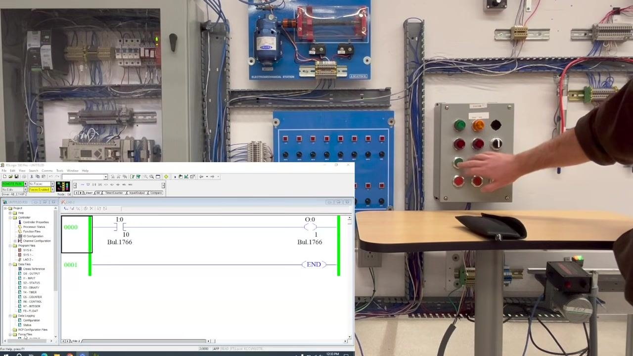
Step 2: Verify output activation in software
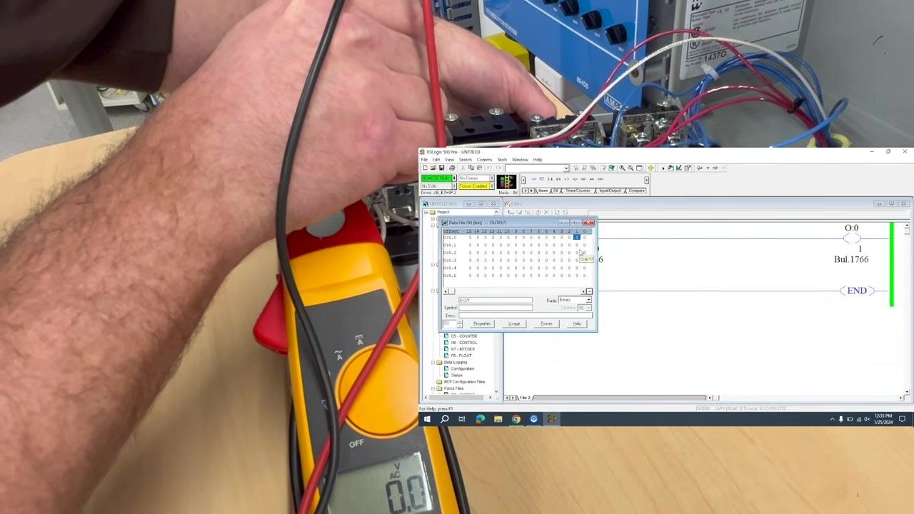
Open the PLC programming software (RSLogix 500 Pro in this example) and locate the ladder logic diagram for the output in question. Press the green push button on the control panel and watch the software to confirm that this action triggers output O:0/1 on slot zero. In this case, the software shows the output being activated, but the corresponding indicator light does not turn on.
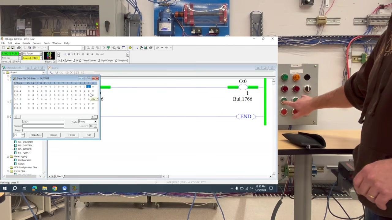
Step 3: Check the output data table
In the software, open the output data table (File O0) and confirm that the bit for the output (O:0/1) changes from 0 to 1 when you press the green push button. This confirms that the PLC is attempting to turn on the output. If the bit changes but the light does not turn on, the issue likely lies outside the PLC logic.
Step 4: Begin physical troubleshooting
Because this is a discrete output (on/off), troubleshooting follows a straightforward sequence. The first physical check is the indicator light (bulb) itself. If you already know the bulb is good, proceed to the next step; if you are unsure, replace or test the bulb first to rule out a simple failure.
Step 5: Measure the output voltage
Determine the expected voltage type and level for the output (for example, 24V DC or 120V AC), and set your multimeter or clamp meter to the matching AC or DC setting. Access the wiring at the back of the control panel where the output is connected, then place the meter probes across the output terminals while the output is activated.
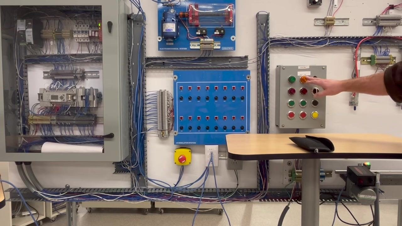
Step 6: Interpret the voltage reading
If the correct voltage is present at the output terminals when the output is activated, the wiring and PLC output are functioning correctly, and the issue may lie with the load — for example, the light or its wiring. If no voltage is present, the problem may be with the PLC output module, the wiring, or a blown fuse.
Step 7: Confirm output voltage type before measuring
Observe the wiring at the output terminal. A red wire typically indicates AC voltage, but do not rely on wire color alone. Always verify the voltage type using the schematic or by direct measurement. If you are unsure of the voltage type, set your meter to both DC and AC settings and measure to confirm before continuing. In this example, the circuit is confirmed as AC.
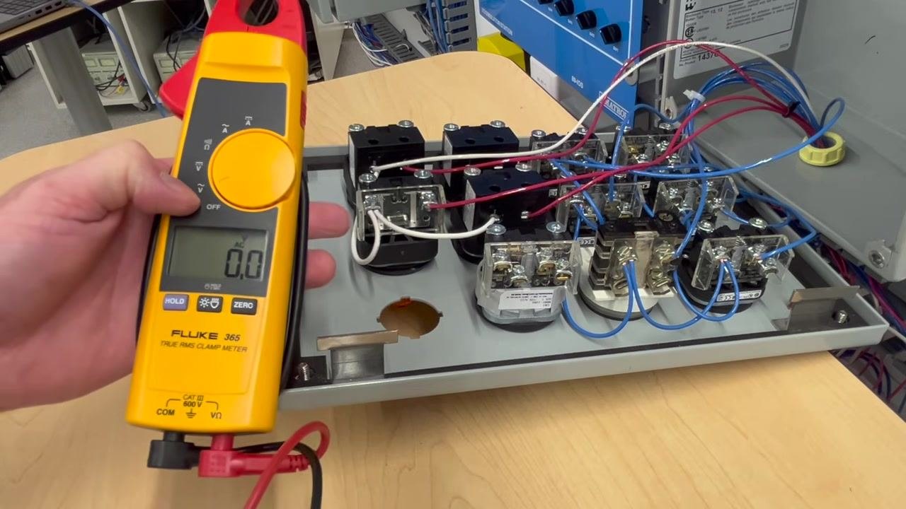
Step 8: Measure voltage at the output terminals
Place the meter probes across the output terminals while the output is activated, and refer to the schematic if needed to confirm the correct measurement points. In this case, the display shows 0.0V AC, indicating no voltage is present at the output.
Step 9: Correlate software and physical output
Check the RSLogix 500 Pro software again to confirm that the output is being logically activated. The output data table and ladder logic show the output bit (O:0/1) set to 1, while the meter still reads 0.0V AC. This confirms that the PLC is attempting to activate the output, but no voltage reaches the terminal.
Step 10: Rule out the load as the problem
Because the output is being activated in software but no voltage is present at the terminal, the issue is not with the load, such as the indicator light or device itself. Close up the output terminal area and prepare to trace the wiring further upstream.
Step 11: Trace wiring back to the control panel
Visually inspect the wiring path from the output terminal back to the control panel. In this setup, there are no intermediate terminal blocks between the output and the control panel, so you can move directly to investigating faults inside the main control panel.
Step 12: Prepare for further diagnostics
Stand in front of the control panel and review the wiring connections to plan whether the issue is a wiring problem or a faulty PLC output.
Step 13: Force the output in software for testing
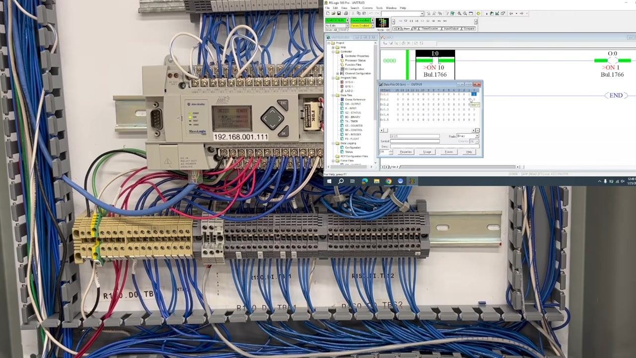
Use the PLC programming software to force the output ON for further testing, then monitor the physical indicator light to see if it responds. In this case, the output is forced ON in software, but the indicator light remains OFF, confirming the issue persists.
Step 14: Establish a reliable neutral and hot line reference
Locate a terminal block where you are certain of a consistent 120V AC supply, and confirm exactly where your neutral connection is sourced from to avoid measurement errors. Place one meter probe on the neutral terminal and the other on the hot line terminal, and confirm that you read approximately 120V AC.
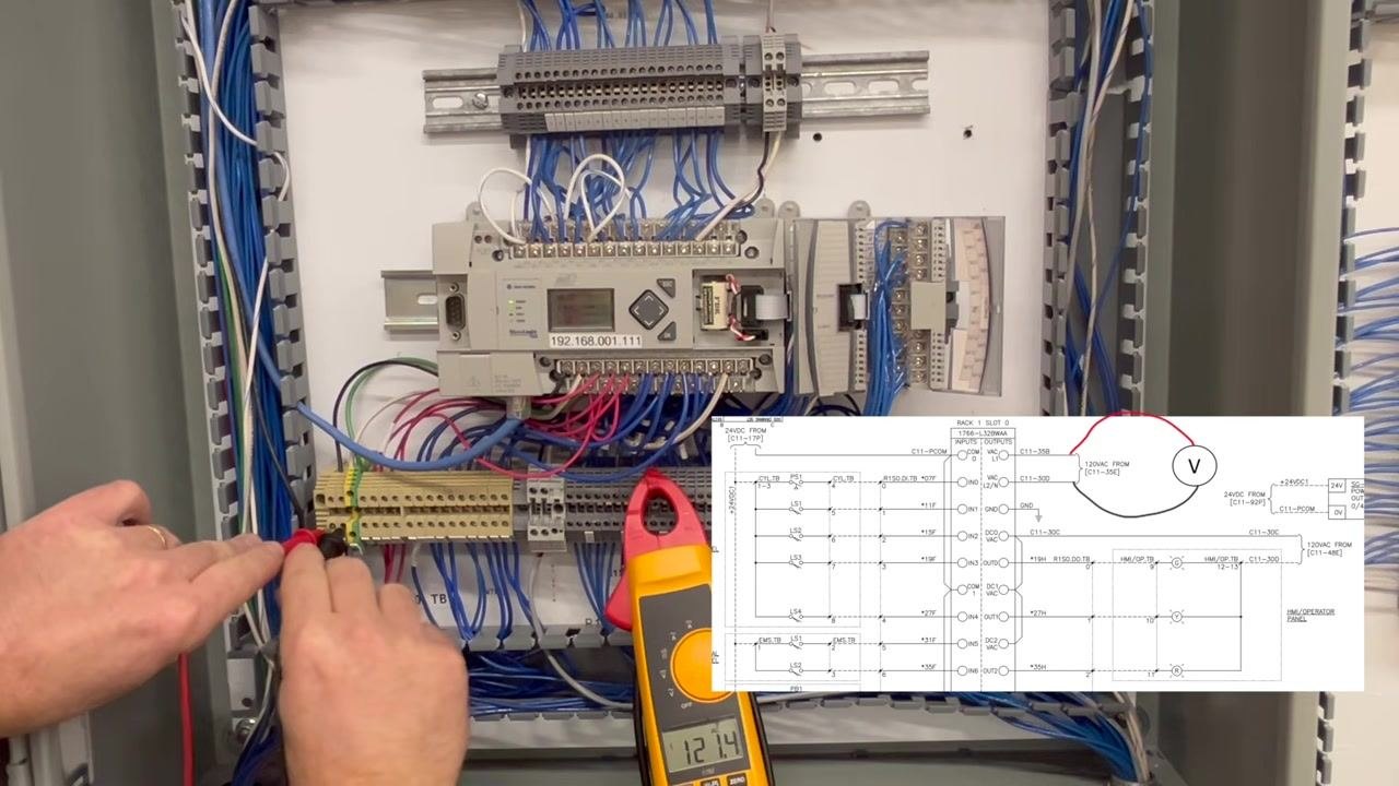
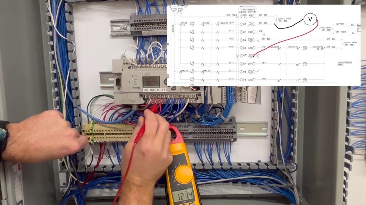
Reference check: Keep the neutral probe in the same terminal for all subsequent measurements so that every reading is relative to a known good neutral. The image below confirms this stable reference point of approximately 121.4V.
Step 15: Test the output terminal block connection
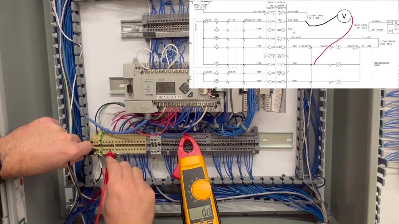
Move the hot probe to the terminal block connection that corresponds to the output wire running to the indicator light. If the display shows 0.0V, no voltage is present at this terminal. Repeat this check on adjacent terminals as needed to confirm the absence of voltage.
Step 16: Interpret the measurement results
If you measure 120V at the main supply terminals but 0V at the output terminal, the terminal block itself is not the source of the fault. A drop in voltage between two adjacent terminals, while rare, can indicate a break in the terminal block. Since no voltage is found at the output terminal in this case, continue tracing the circuit upstream toward the PLC output.
Step 17: Continue tracing toward the PLC output
Identify which output on the PLC corresponds to the circuit under test — for example, Output 1, typically located on the top row of the PLC module — and prepare to test voltage directly at the PLC output terminal to further isolate the fault.
Step 18: Test the output voltage at the suspected output terminal
Place the multimeter probes on the output terminal and the corresponding neutral/ground terminal as shown, referring to the schematic overlay to confirm probe placement. The multimeter display reads 0.0 volts, confirming no voltage is present at this output.
Step 19: Confirm the output is not closing
Keep the probes in place and verify that the multimeter still reads 0.0 volts. This confirms that the PLC output contact is not closing as expected.
Step 20: Verify voltage at the output contact
Move the red probe to the output contact terminal as indicated in the schematic. The multimeter now reads 121.4 volts, confirming that power is available up to the contact, even though it is not passing through to the output.
Step 21: Diagnose the PLC output as faulty
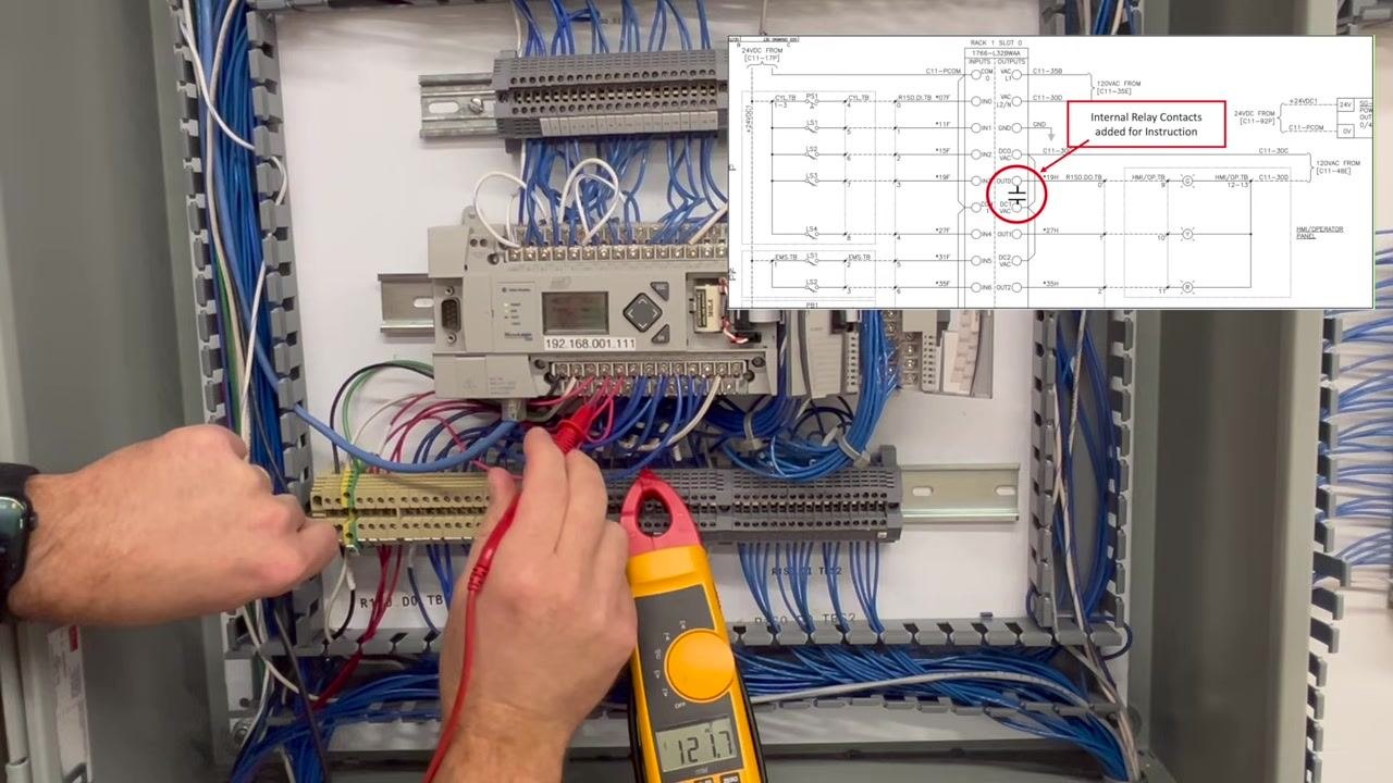
Continue measuring at the output contact. The multimeter reads 127.7 volts at the contact but 0.0 volts at the output, showing that the contact for this output is not closing. This means the PLC output itself is bad; there is no repair available for this output, but you can either swap the PLC or move the load to a functioning output.
Step 22: Remove probes and prepare for further testing
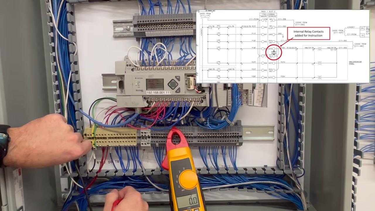
Remove the red probe from the terminal block, leaving the black probe in place. The multimeter display returns to 0.0 volts, and the schematic overlay continues to highlight the internal relay contacts.
Step 23: Trace the power path for verification
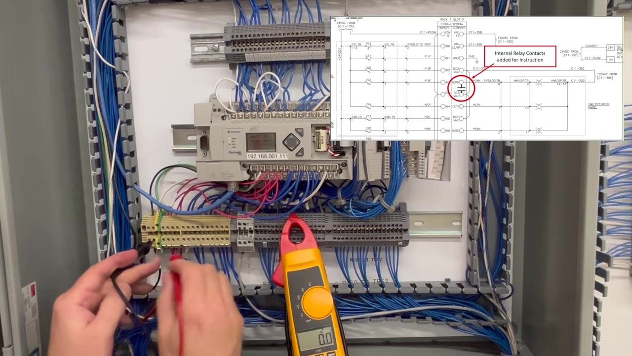
Use both probes to trace the power path through the terminal block and wiring, following the schematic to confirm continuity and voltage presence along the expected route.
Step 24: Continue tracing and confirming the power path
Continue checking additional points along the wiring with the probes. The multimeter continues to read 0.0 volts, confirming that the output is not delivering voltage anywhere along this section.
Step 25: Confirm the wiring is intact
Trace the power line through the remaining sections of wiring. The wiring itself is confirmed intact, isolating the issue to the PLC output relay or contact rather than the wiring path.
Step 26: Conclude that the output is bad
With the wiring confirmed good, the conclusion is that the PLC output itself is bad, not the wiring. Both probes are held in hand while the multimeter reads 0.0 volts, and the schematic overlay highlights the faulty relay contact.
Step 27: Review the PLC logic in RSLogix 500
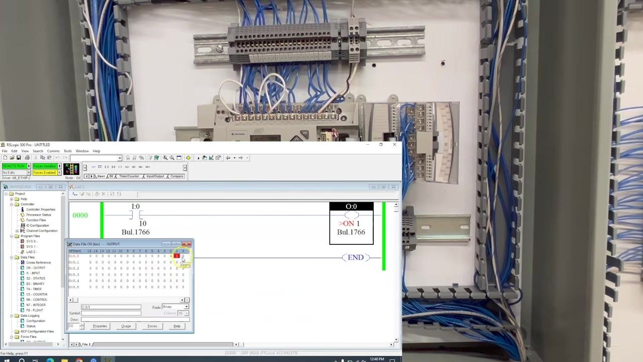
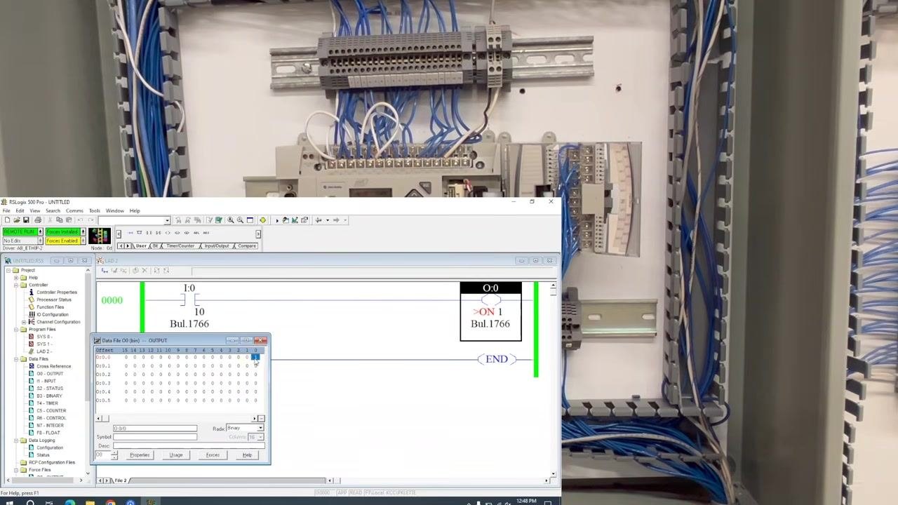
Open the RSLogix 500 Pro software interface and review the ladder logic diagram showing the input and output rungs. The output (O:0/0) is forced ON, highlighted in red in the data file window, and the status bar indicates "Force Enabled" and "Process Inhibited". This confirms the PLC logic is commanding the output ON, even though the physical output is not functioning.
Step 28: Confirm output status and remote run mode
Review the software interface again, displayed on a computer screen in front of the open control panel. The ladder logic shows an input (I:0/10) and an output (O:0/0), with the output highlighted and marked "ON 1" (forced ON). The status bar indicates "REMOTE RUN", "Force Enabled", and "Process Inhibited", and the Data File (O) window shows O:0/0 set to 1. This step confirms in software only, with no physical action performed, that the PLC logic is commanding the output ON.
Step 29: Measure voltage at the output terminal block
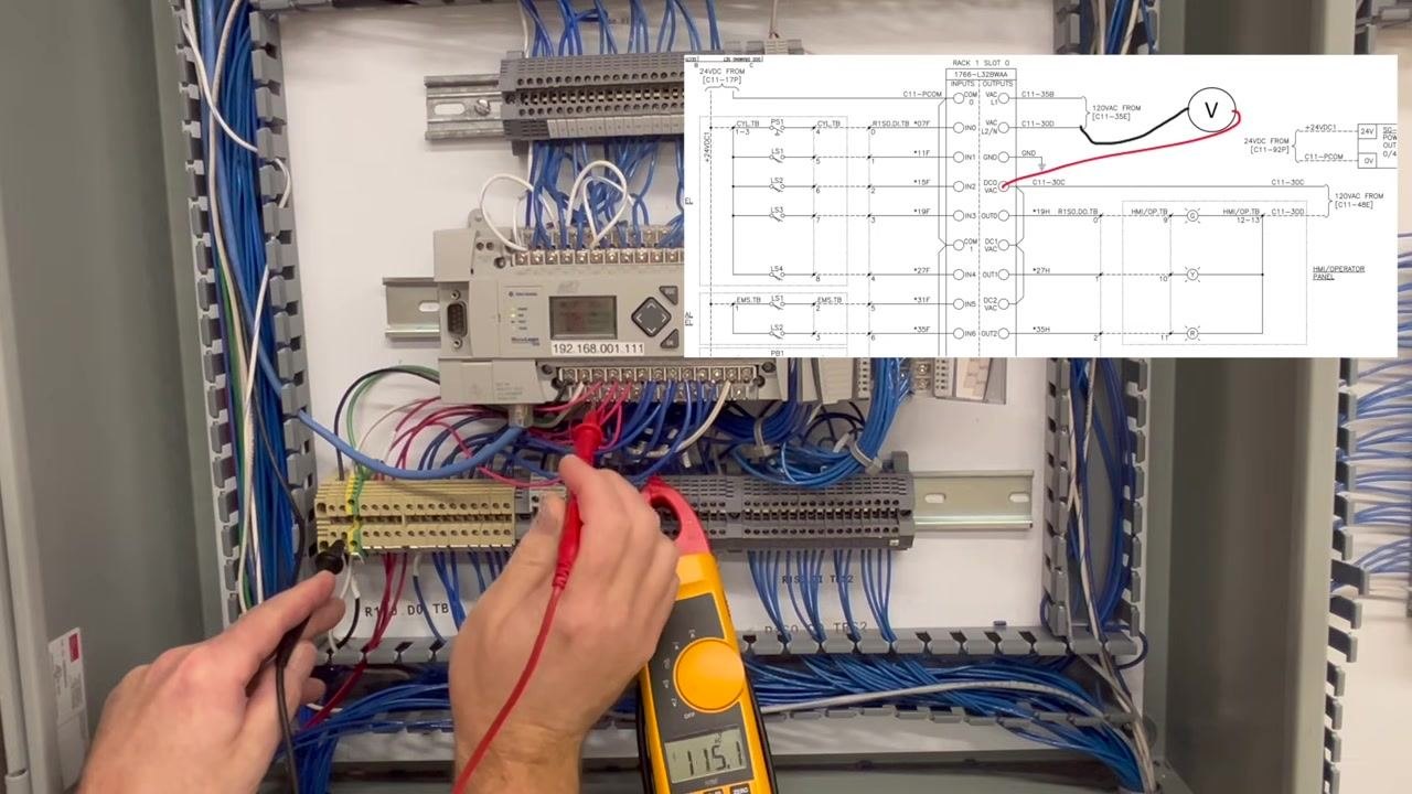
In the control panel, use the digital clamp meter to measure voltage at the output terminal block. Place the black probe on the neutral/ground terminal and the red probe on the output terminal as indicated in the schematic overlay. The meter reads 115.1 volts, confirming that 120V AC is available at this point, matching the schematic.
Step 30: Continue tracing voltage through the output path
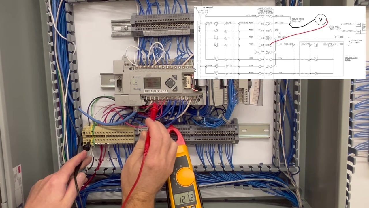
Move the red probe to the next terminal in the output path as shown in the schematic overlay. The meter now reads 121.2 volts, confirming that the output circuit is energized further along the path.
Step 31: Verify voltage at the final output terminal
Remove the red probe and place it at the final output terminal, leaving only the black probe in contact with the terminal block. The meter now reads 0.0 volts, confirming that despite the PLC logic commanding the output ON, no voltage reaches the final output terminal — a failure in the output relay or contact.
Verification and summary
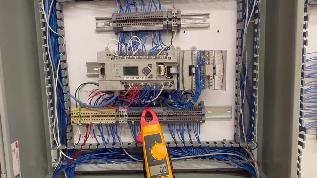
Review the completed measurements: the control panel remains open, showing the PLC, terminal blocks, and organized wiring, with the digital clamp meter resting on the terminal block and displaying 0.0 volts. No probes are held at this point, marking the end of the troubleshooting sequence.
The control panel setup remains unchanged in the final check, with the digital clamp meter still resting on the terminal block and displaying 0.0 volts, marking the conclusion of the PLC output troubleshooting procedure.
By following this procedure, you have:
- Confirmed the PLC is sending the output signal in software using RSLogix 500 Pro.
- Checked the physical indicator (bulb) to rule out a simple load failure.
- Measured voltage at the output terminals with the correct meter setting, using the schematic to verify measurement points.
- Traced voltage systematically from a known good neutral and hot line reference through the terminal blocks and output contact.
- Confirmed the output relay/contact is not passing voltage, isolating the fault to the PLC hardware.
What's next
Since the PLC output relay/contact is confirmed faulty and cannot be repaired, your corrective options are to swap out the PLC or move the affected load to a functioning output on the same module.
Generation details: cost, quality tiers
Docsie billed 4,000 credits ($2.80) to analyze this 8-minute video at standard quality. The rewrite, template fill and Word/PDF exports were included. The same video at each quality tier:
| Quality | Frames sampled | Credits | Approx. cost |
|---|---|---|---|
| Draft | every 16-30 s | 2,000 | $1.40 |
| Standard (this guide) | every 8-15 s | 4,000 | $2.80 |
| Detailed | every 4-7 s | 8,000 | $5.60 |
| Ultra | every 1-3 s | 16,000 | $11.20 |
Credits priced at $0.70 per 1,000; plans include a monthly allowance. Enterprise customers on on-premise or bring-your-own-model deployments run this on their own inference and pay no per-video credits.
Generated by Docsie Video-to-Docs on 2026-09-14 from a 7-minute video. Screenshots are frames from the source video and belong to their creator, KletteTech, whose original is embedded above. If you own this video and want the guide removed or credited differently, contact us and we will act within one business day.