
How to Tig Weld
This procedure explains how to TIG weld using a basic stick (SMAW) machine or a dedicated AC/DC TIG welder, covering equipment selection, torch assembly, gas setup, arc starting, and welding technique. Follow the steps in order to safely prepare your equipment and complete your first TIG welds.
Video: TIG Welding 101 // Basics In Under 15 MIN! by DIY PRO (2023). All credit for the demonstration goes to the creator; watch the original on YouTube. The written guide below was generated from this video by Docsie. Creator? Request a change or removal.
This procedure explains how to TIG weld using a basic stick (SMAW) machine or a dedicated AC/DC TIG welder, covering equipment selection, torch assembly, gas setup, arc starting, and welding technique. Follow the steps in order to safely prepare your equipment and complete your first TIG welds.
Purpose
This SOP provides a step-by-step method for setting up a TIG welding station, assembling the TIG torch, selecting tungsten electrodes and filler rod, connecting gas supply, and starting and controlling the arc for both beginner and more advanced TIG welding setups.
Scope
This procedure applies to entry-level stick (SMAW) machines used for basic TIG welding as well as dedicated AC/DC TIG welders with digital controls, such as machines offering pulse, pre-flow/post-flow, and foot-pedal amperage control. It covers steel welding fundamentals and references aluminum welding as a next step for more experienced users.
Required equipment and PPE
- DC or inverter-style stick welder, or a dedicated AC/DC TIG welder
- TIG torch (17V torch recommended for general-purpose work)
- Filler rod (ER70S-2 recommended for beginners working with steel)
- Tungsten electrodes in your chosen composition and a 3/32" (2.4 mm) diameter for general use
- Gas cylinder filled with 100% argon
- Gas regulator or flow meter rated for CO2/argon or 100% argon
- Welding helmet
- Welding gloves
- Stable, metal workbench
- Ground clamp
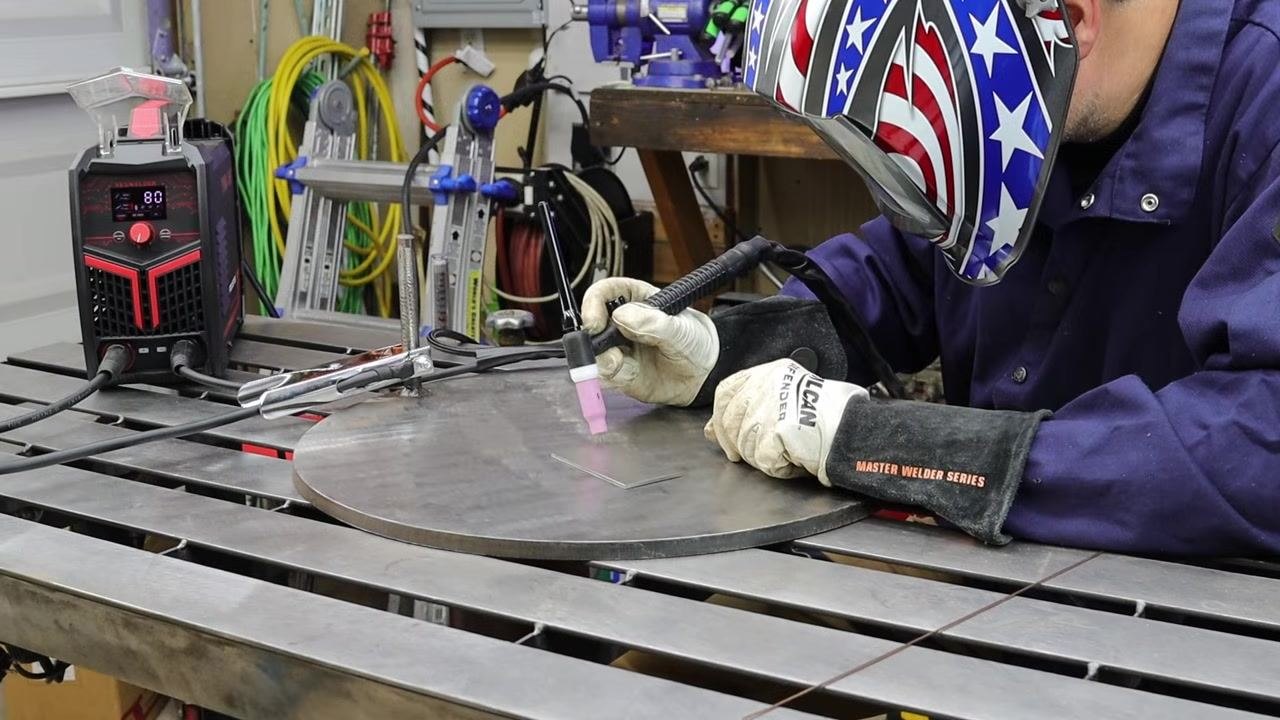
Safety note: Wear a welding helmet and gloves at all times while welding.
Procedure
Set up a basic stick machine for TIG welding
- Gather a DC or inverter-style stick welder. Any basic stick machine will work for entry-level TIG welding.
- Collect the following essential items: TIG torch, filler rod, tungsten electrodes, a gas cylinder filled with 100% argon, and a gas regulator compatible with CO2/argon or 100% argon.
- Put on your welding helmet and gloves before beginning any welding activity.
-
Recognize that a basic stick machine can be used for TIG welding, but dedicated TIG machines offer additional features and options at a higher cost.
-
Use only 100% argon gas for TIG welding. Do not substitute C25 (75% argon/25% CO2) MIG welding mix, as it is not suitable for TIG welding.
- Search for local welding gas suppliers rather than buying gas online to save money, as local suppliers often offer better prices.
- Attach a flow meter or regulator designed for CO2/argon or 100% argon to your gas cylinder. Both inexpensive and expensive regulators can work, but always check for leaks.
- Set the gas flow rate to 15–20 CFH (Cubic Feet per Hour).
- Safety note: Always close the main valve on the gas cylinder completely when you finish welding. Failing to close the valve can result in an empty gas bottle by the next day.
-
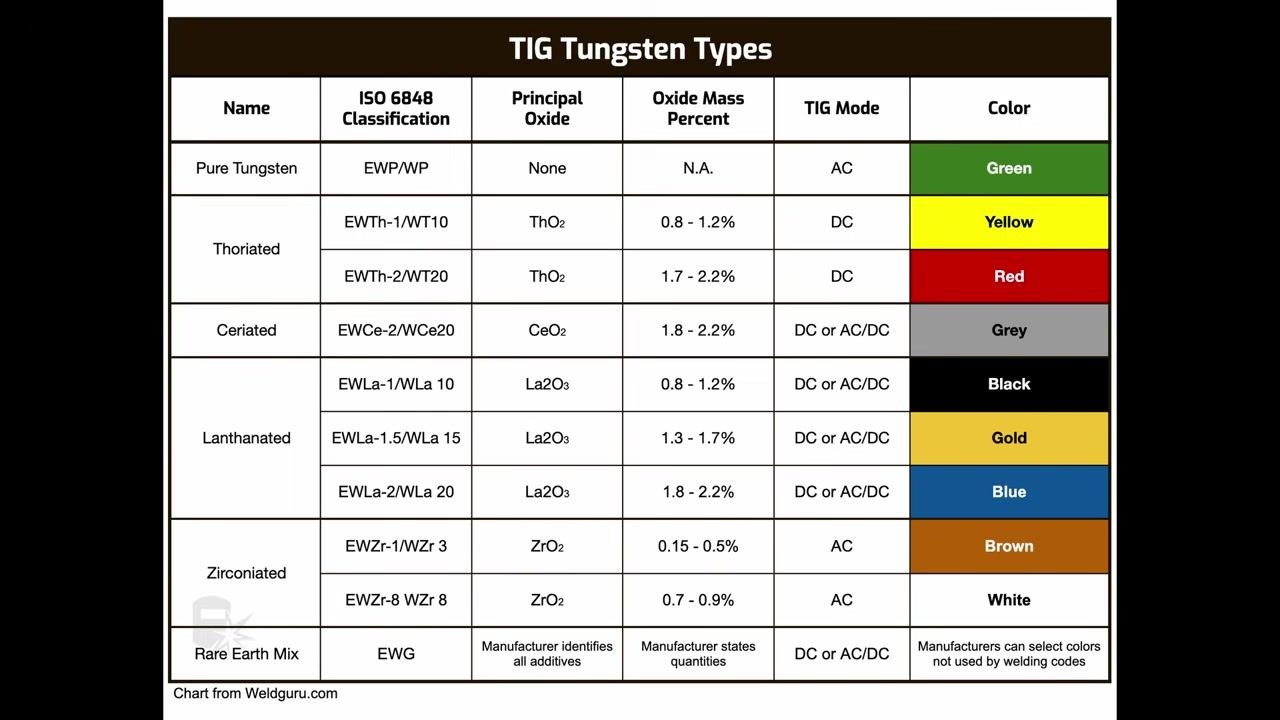
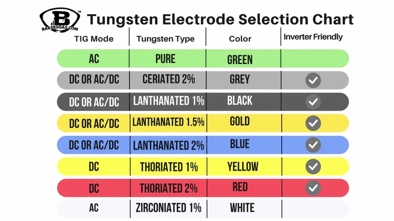
Review the available tungsten electrode types. Each is identified by a color code that indicates its composition. Do not choose a color based only on whether it is marketed for steel or aluminum; instead, refer to the electrode's composition and intended use.
-
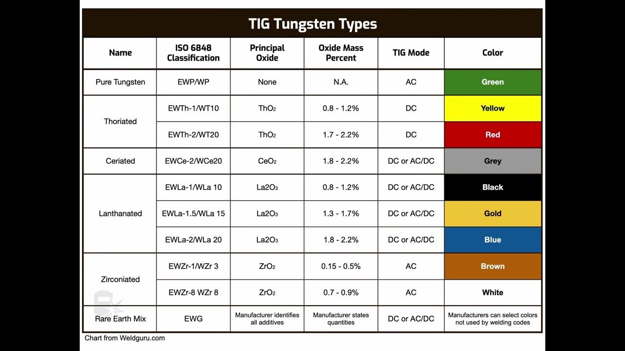
Reference a tungsten type chart to confirm compatibility:
- Pure Tungsten (Green): AC welding
- Thoriated (Yellow, Red): DC welding
- Ceriated (Grey): DC or AC/DC
- Lanthanated (Black, Gold, Blue): DC or AC/DC
- Zirconiated (Brown, White): AC welding
- Rare Earth Mix: Manufacturer-specific
The chart lists ISO classifications, oxide types, percentages, TIG mode compatibility, and color codes.
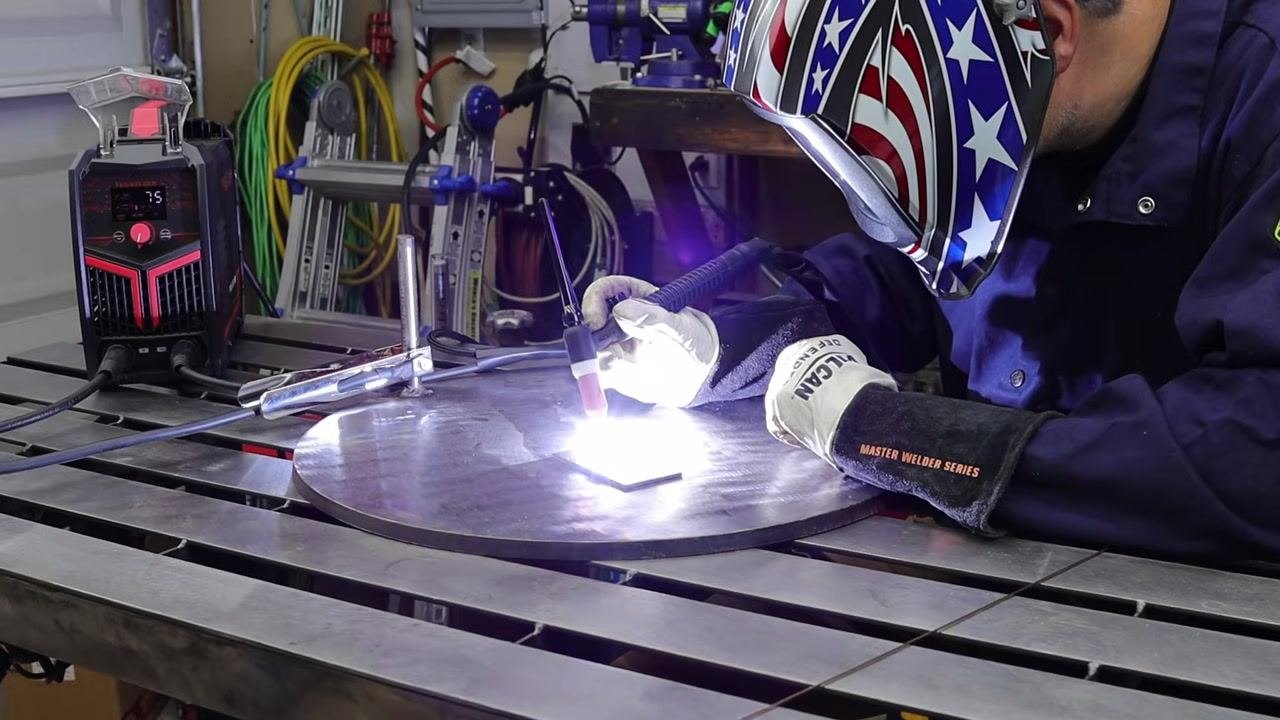
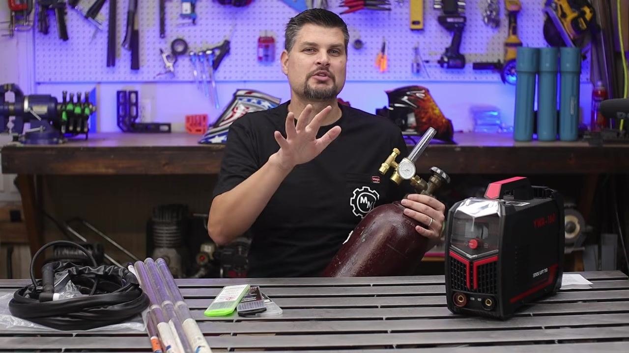
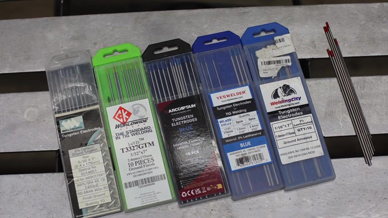
Select tungsten electrodes and filler rod
- Confirm the correct tungsten type for your application using the same reference chart: Pure Tungsten (Green) for AC welding, Thoriated (Yellow, Red) for DC welding, Ceriated (Grey) for DC or AC/DC, Lanthanated (Black, Gold, Blue) for DC or AC/DC, Zirconiated (Brown, White) for AC welding, and Rare Earth Mix electrodes according to manufacturer specifications.
- Choose an electrode capable of both AC and DC welding for versatility. Grey (Ceriated) and blue (Lanthanated 2%) electrodes are common, reliable choices. Newer chartreuse (green-blue-yellow) electrodes also work well for both AC and DC.
- Select the electrode diameter based on material thickness: use a smaller diameter for thinner material and a larger diameter for thicker material. Use 3/32" (2.4 mm) tungsten for general-purpose TIG welding, as this size suits most beginner projects.
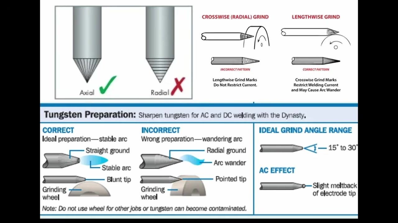
- Grind the tungsten tip to a point before welding. Use an angle grinder while spinning the electrode by hand, or use a bench grinder with a drill for a more precise point.
-
Always grind the tungsten lengthwise (axially), not crosswise (radially), to maintain a stable arc and prevent arc wandering. Keep the grind angle within 15° to 30°. Expect a slight meltback of the electrode tip during AC welding.
-
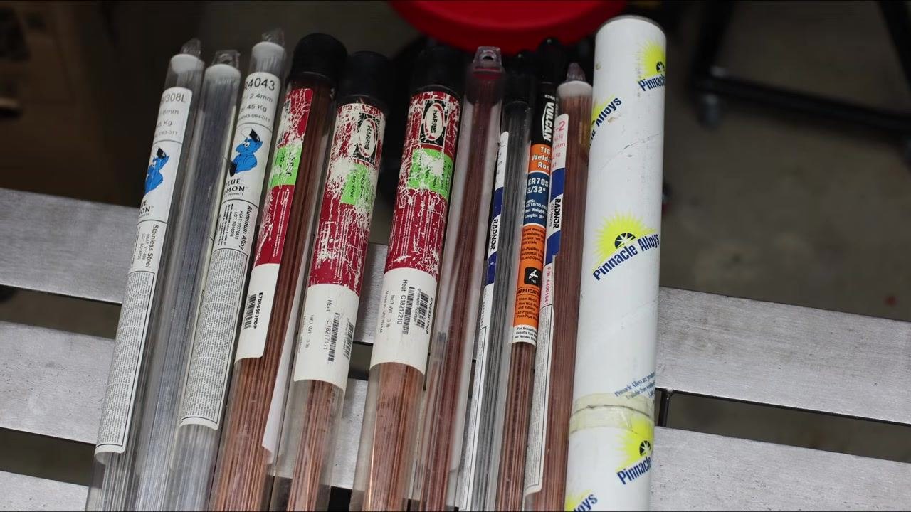
Select a filler rod for TIG welding, which requires adding filler material to build the weld. Start with steel rather than aluminum for easier results.
- Use ER70S-2 filler rod as a reliable, all-purpose choice for beginners working with steel. As with tungsten, select thinner rods for thin material and thicker rods for thicker material.
Select and connect the TIG torch
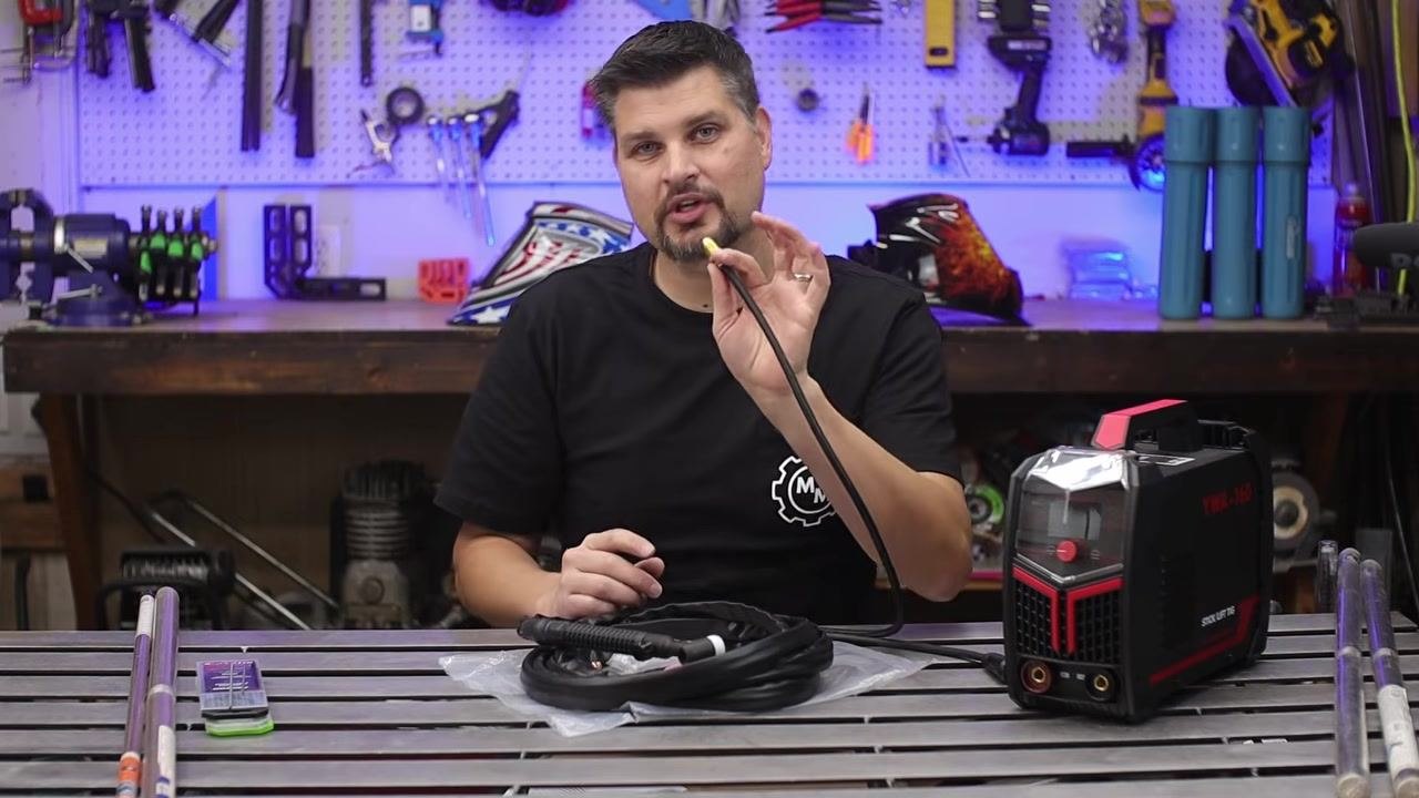
- Choose a 17V TIG torch for general-purpose welding. The "17" indicates a medium, versatile torch size, and the "V" designates a valve on the torch that allows manual control of shielding gas flow.
- Confirm whether your welding machine has built-in gas solenoids. If your machine is basic or "bare bones" and lacks gas inlets, outlets, or solenoids, you must use a torch with a valve.
- Locate the gas input fitting on the TIG torch hose. This fitting connects directly to your gas regulator or flow meter. Most entry-level or budget TIG welders require this direct connection because they lack internal gas solenoids.
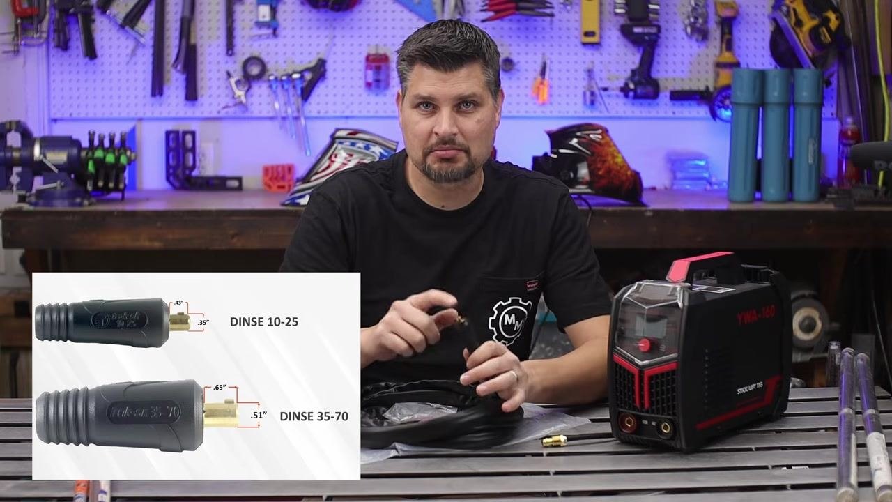
- Identify the correct DINSE connector size for your machine's negative terminal. There are two common sizes: DINSE 10-25 (smaller, pin diameter approximately 0.35", body diameter approximately 0.43") and DINSE 35-70 (larger, pin diameter approximately 0.51", body diameter approximately 0.65").
- Insert the correct DINSE connector into the negative (-) terminal of your TIG welder, ensuring the connection is secure and fully seated. Attach the gas hose from the torch directly to your gas regulator or flow meter.
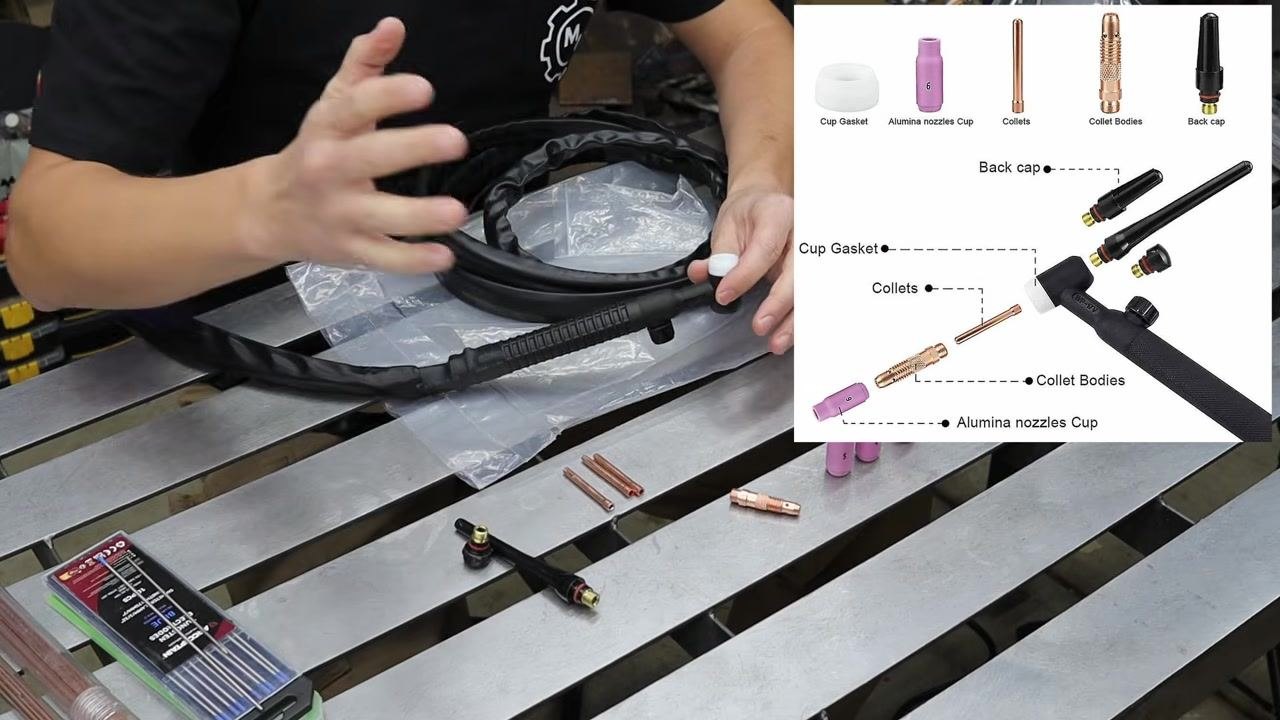
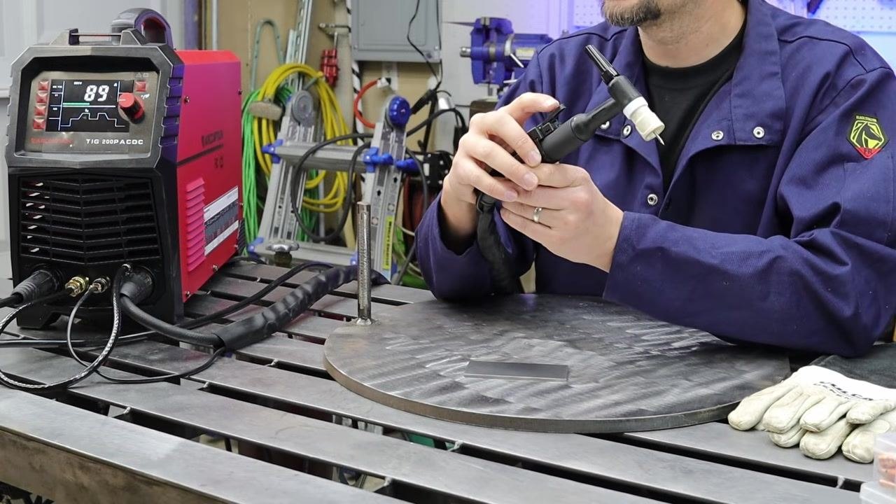
- Familiarize yourself with the main torch components before assembly: the white insulator (provides electrical insulation), the back cap (seals the rear of the torch and holds the tungsten in place), the collet and collet body (secure the tungsten electrode), and the cup (directs shielding gas over the weld area). Assemble these components according to your torch's instructions.
Assemble the TIG torch front end
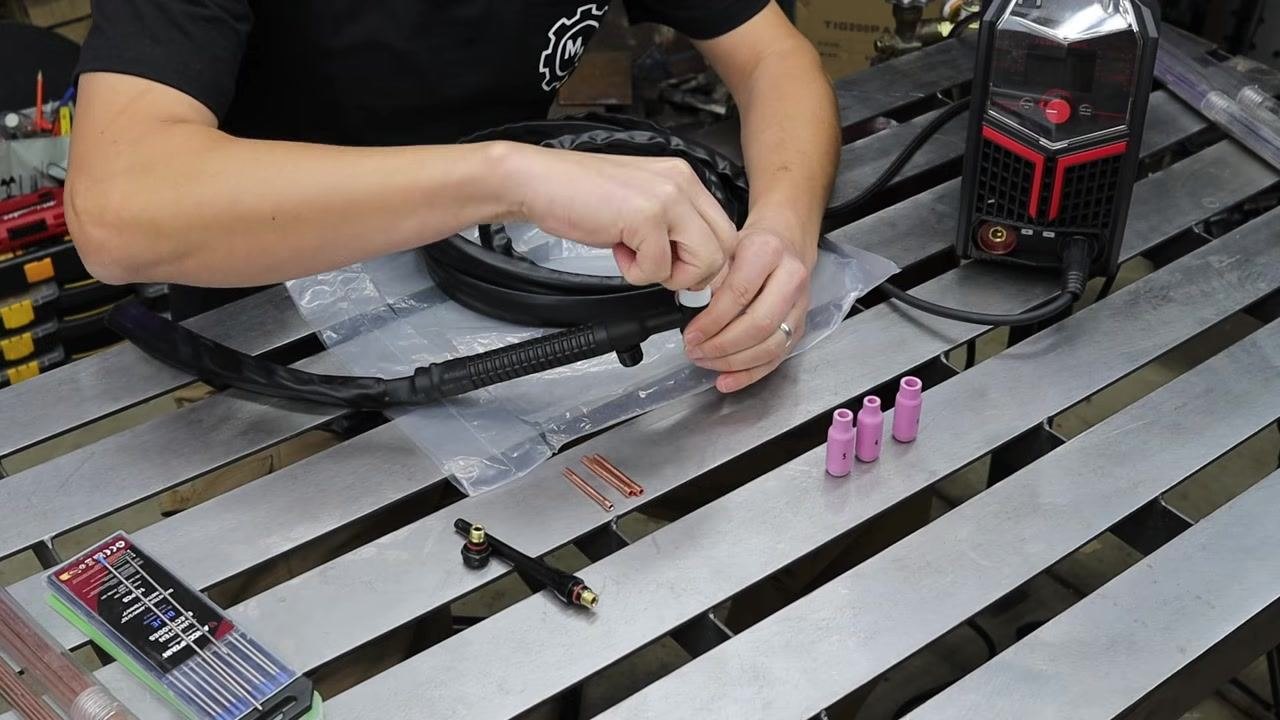
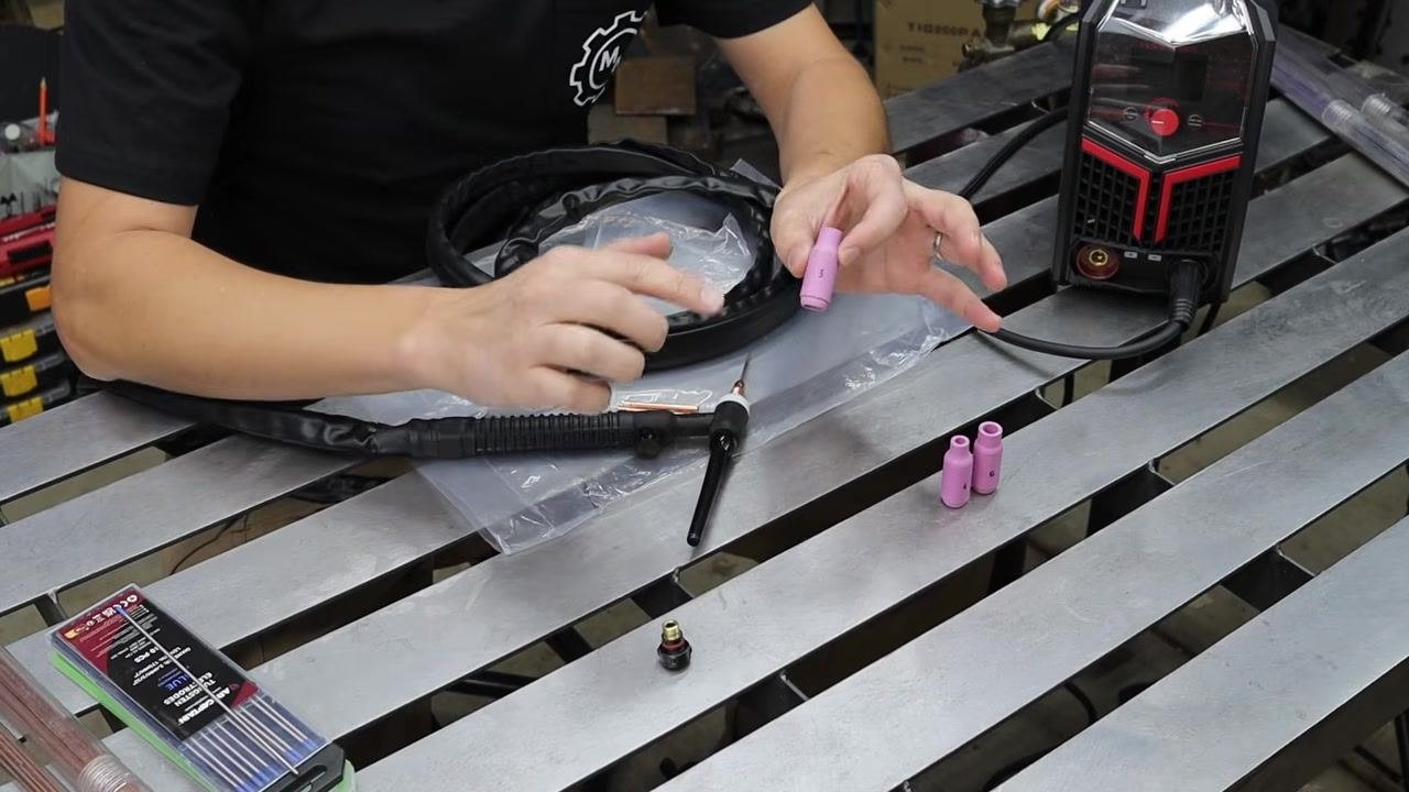
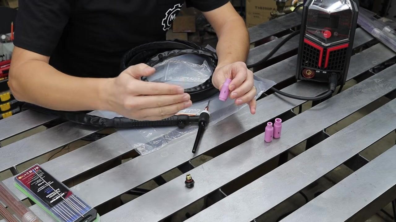
- Lay out all TIG torch front-end components on your workbench, including the torch body, cup gasket, alumina nozzle cups (labeled with numbers), collets, collet bodies, and back caps. Keep your tungsten electrodes and TIG welder nearby, and refer to a parts diagram if available.
-
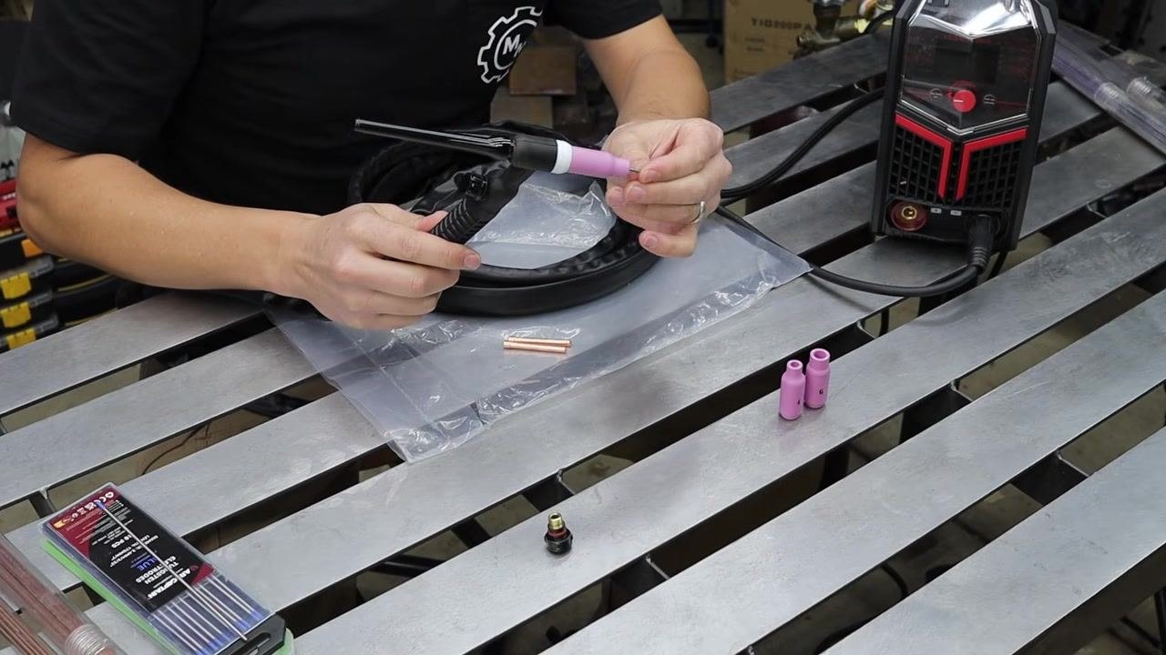
Thread the white cup gasket and the pink alumina nozzle cup onto the front of the TIG torch head by hand. Tighten until snug, but do not overtighten.
-
Select the collet that matches your tungsten electrode size (for example, 3/32"). Hold the collet in one hand and the tungsten electrode in the other in preparation for insertion.
-
Choose the appropriate back cap for your tungsten length: a short back cap for short tungsten, or a long back cap for longer tungsten. The back cap is required to secure the tungsten in place.
-
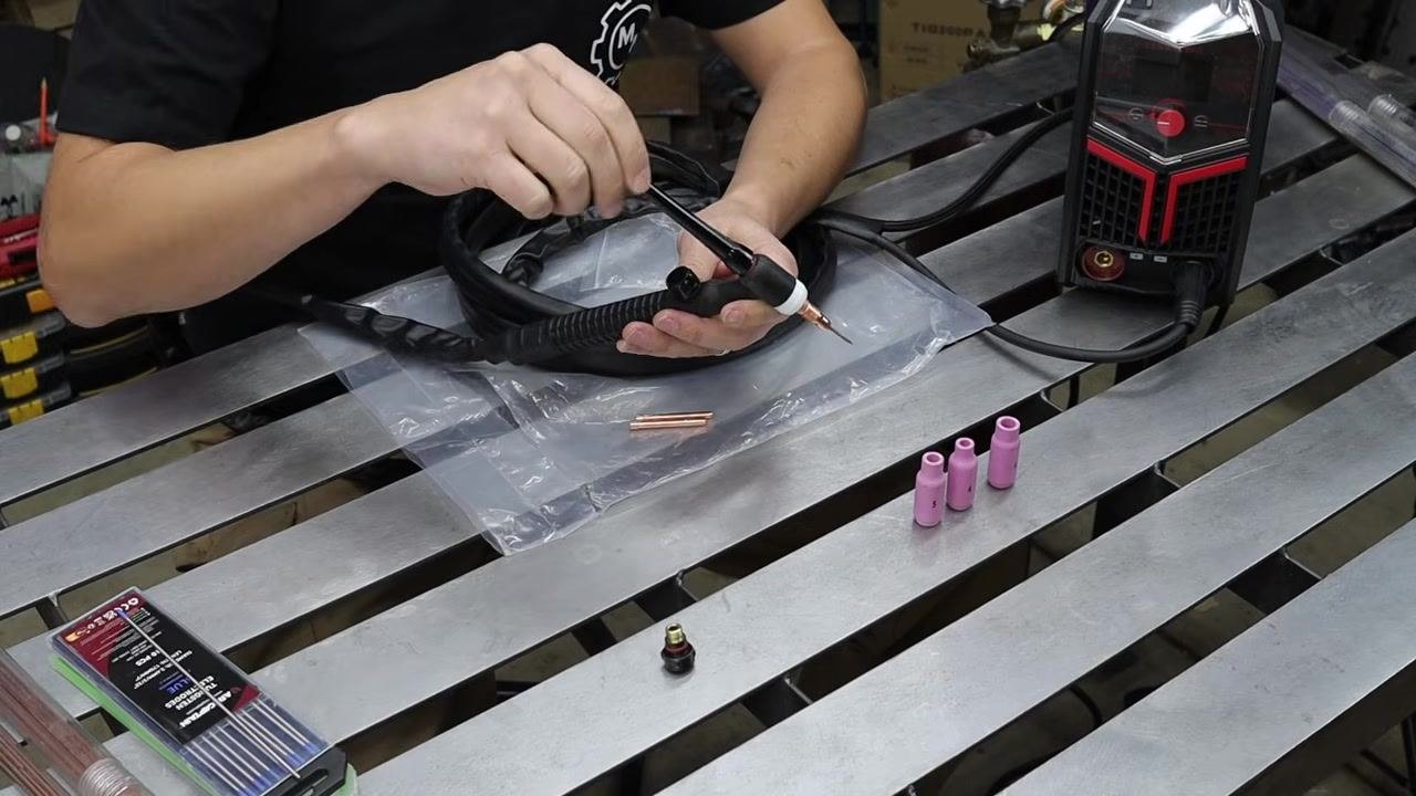
Insert the tungsten electrode through the back of the torch, sliding it through the collet and collet body. Thread the back cap onto the torch and tighten it by hand; as you tighten, the collet crimps down on the tungsten to hold it securely.
-
Examine the pink alumina nozzle cups, each labeled with a number (for example, 5 or 6). The number indicates the diameter of the cup opening in 1/16" increments, so a "5" cup has a 5/16" opening. Choose the cup size appropriate for your welding needs.
-
Confirm the cup size by checking the printed number; all cup sizes fit the torch, so selection depends on your application.
-
Adjust the tungsten stick-out so it extends from the cup by approximately the same measurement as the cup opening (for example, about 5/16" for a #5 cup). Visually check the stick-out by holding the assembled torch.
-
Tighten all components—cup, collet, collet body, and back cap—securely, and double-check that the tungsten is held firmly with the correct stick-out (approximately 5/16" for a #5 cup).
Set up the TIG welder and perform your first weld
-
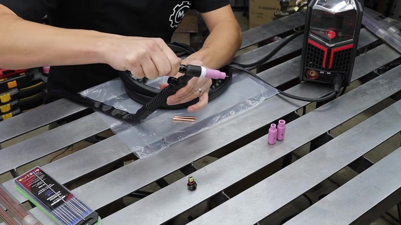
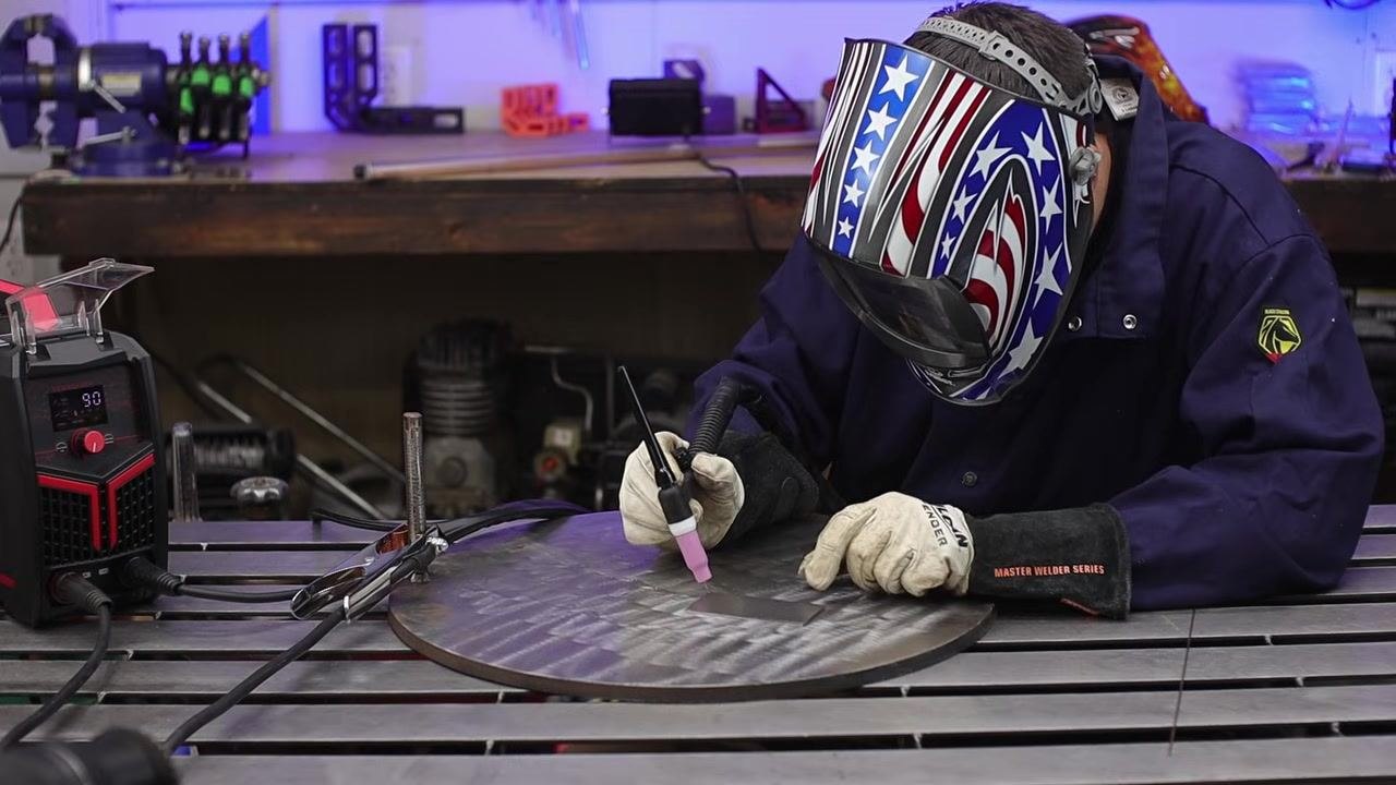
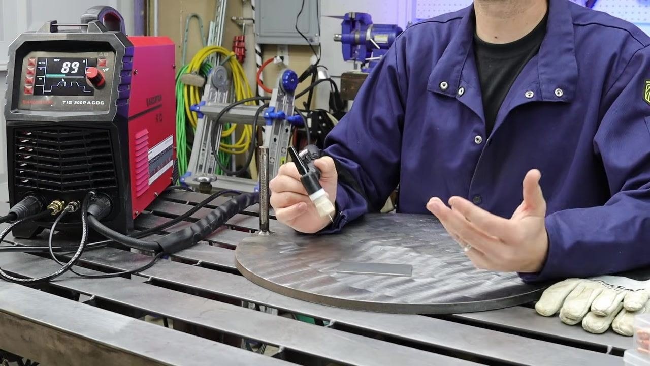
Confirm the tungsten stick-out is correct (about 5/16" for a #5 cup) and that the back cap is tightened securely by hand. Place the fully assembled TIG torch and welder on a stable, metal workbench.
-
Attach the ground clamp to the workpiece or workbench, then power on the TIG welder. Adjust the amperage as needed for your material using the welder's display. Keep your welding helmet and gloves within reach, and hold the TIG torch in your dominant hand, ready to weld.
-
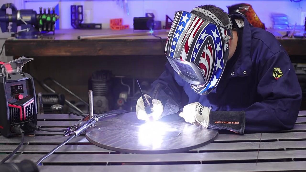
Learn the lift-arc start method: gently touch the tungsten electrode to the workpiece, then quickly lift the torch off the surface to create the arc. Practice this motion carefully to avoid contaminating the tungsten.
-
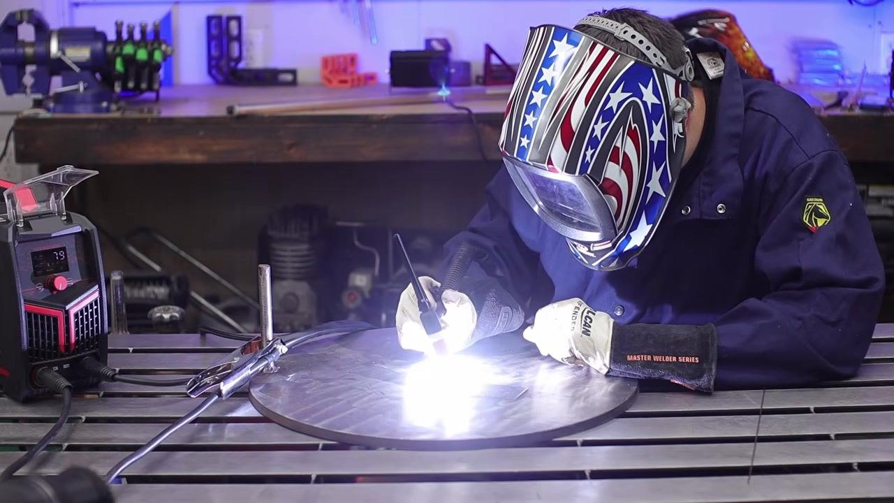
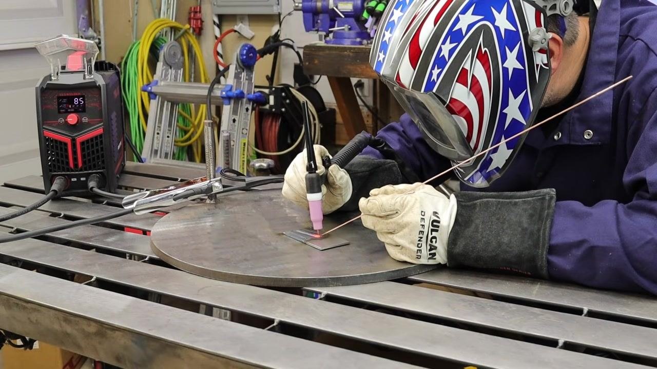
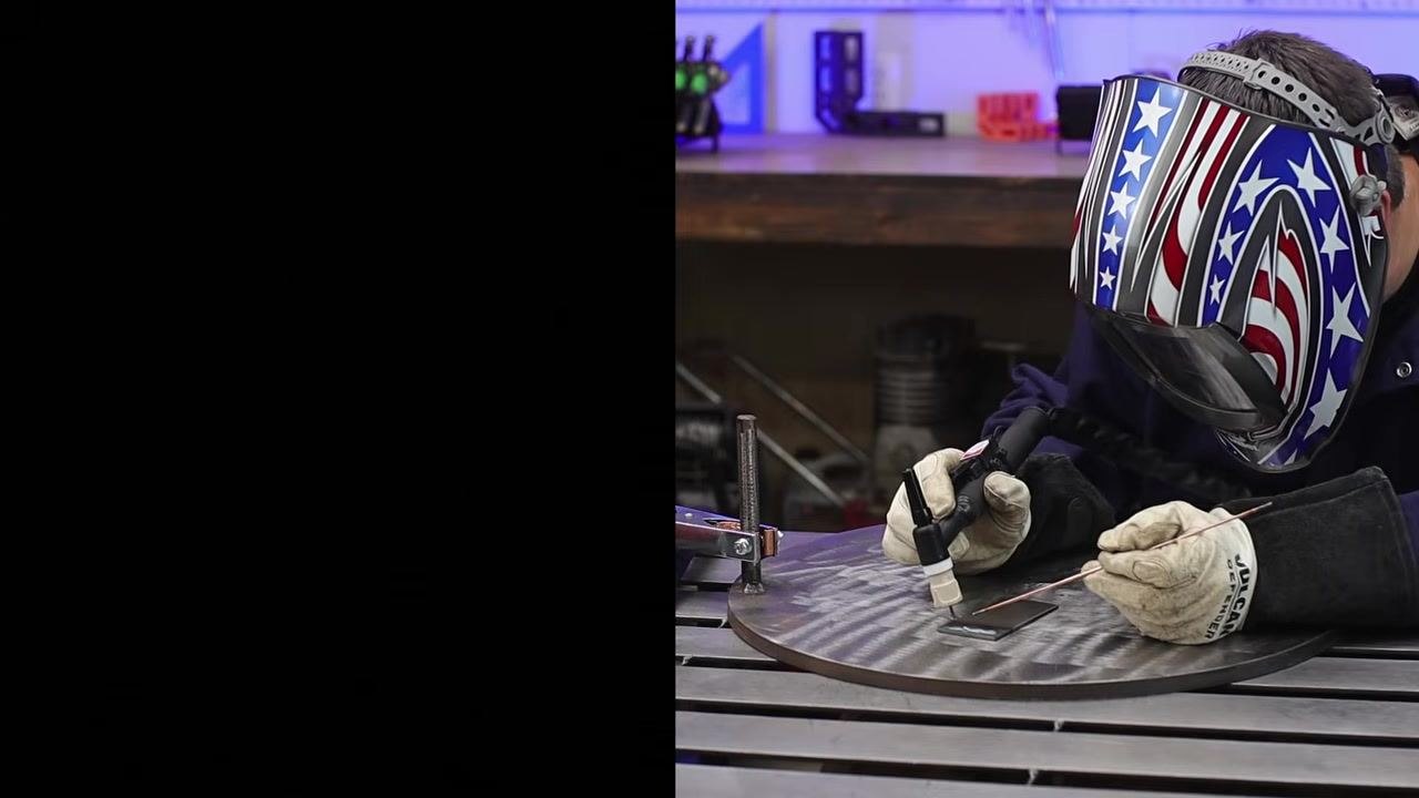
Safety note: Put on your welding helmet and gloves before striking an arc. Hold the torch at a slight angle to the workpiece, touch the tungsten to the metal, then lift off to start the arc. Move the torch steadily along the workpiece to create a weld bead. For this first pass, do not add filler rod—focus on controlling the torch and maintaining a steady arc.
-
Keep the torch at a consistent distance from the workpiece and move smoothly to produce an even weld bead, observing the arc and adjusting hand position as needed.
-
Practice running beads without filler material as a beginner. Focus on torch angle, travel speed, and arc length to build control before introducing filler rod.
-
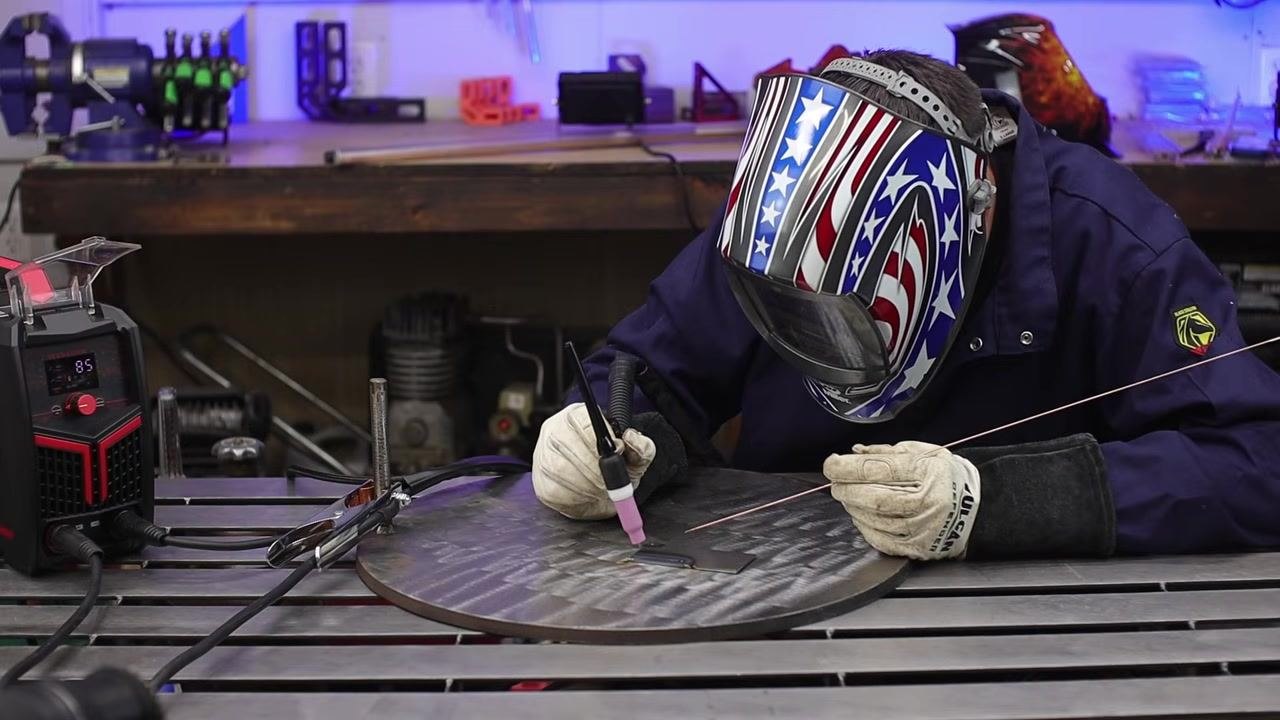
Once comfortable with torch control, begin adding filler rod. Hold the filler rod in your non-dominant hand and feed it into the leading edge of the weld pool as you move the torch, maintaining a steady hand and consistent filler addition.
-
To finish the weld, move the torch away from the workpiece in a controlled manner. Avoid whipping the torch out too quickly, as this can cause weld defects. Allow the weld to cool slightly before removing the torch completely.
- Inspect the completed weld bead for consistency and quality, and note the amperage setting on the welder display (for example, 85 amps).
Understand TIG welder features and settings
-
Recognize that modern TIG welders offer straightforward setup and operation. With basic equipment and a simple setup, you can begin learning TIG welding easily.
-
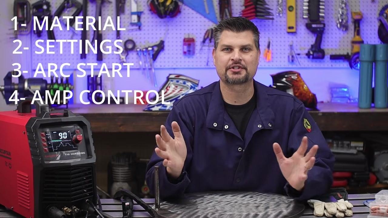
Identify the four key factors for successful TIG welding: (1) Material—the type of metal you are welding; (2) Settings—the welder configuration for the specific job; (3) Arc Start—the method used to initiate the arc; (4) Amperage Control—adjusting current to suit your material and technique.
-
Review the four key setup steps as displayed on screen: 1- MATERIAL, 2- SETTINGS, 3- ARC START, 4- AMP CONTROL. These steps reinforce the fundamentals for beginners.
-
Understand that AC-DC TIG welders can handle both steel (DC) and aluminum (AC). Most AC-DC machines weld steel in DC mode and switch to AC for aluminum.
-
Use DC mode for steel while learning and practicing basic TIG welding, and switch to AC mode when you are ready to weld aluminum.
-
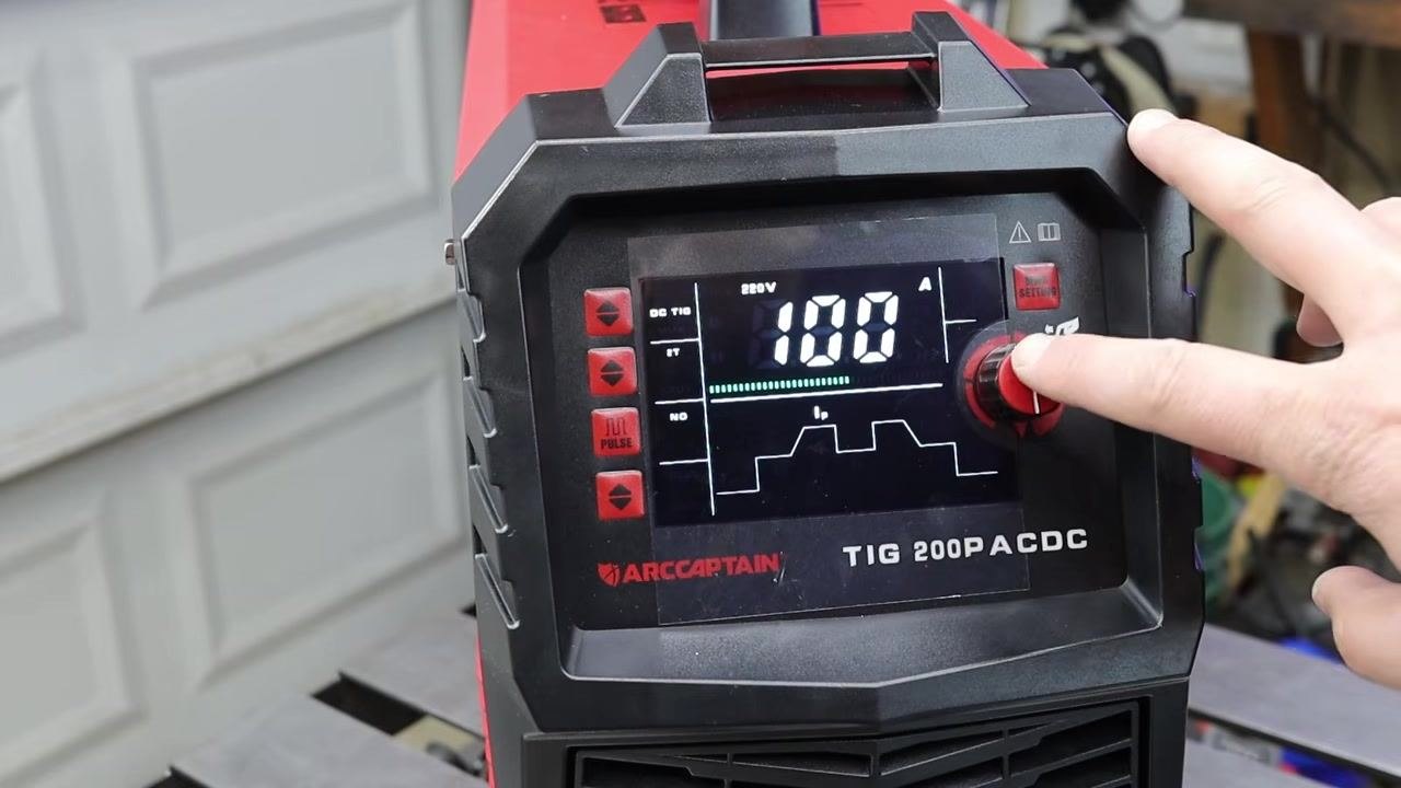
Note the differences in machine adjustability. Some TIG welders, such as the Titanium 200, offer minimal adjustment (on/off and amperage only). Others, such as the ARCCAPTAIN TIG 200P ACDC, provide a digital display and more adjustable settings.
-
Understand that basic machines offer only on/off and amperage controls, while advanced machines with digital displays allow more precise adjustments and greater control over welding parameters.
-
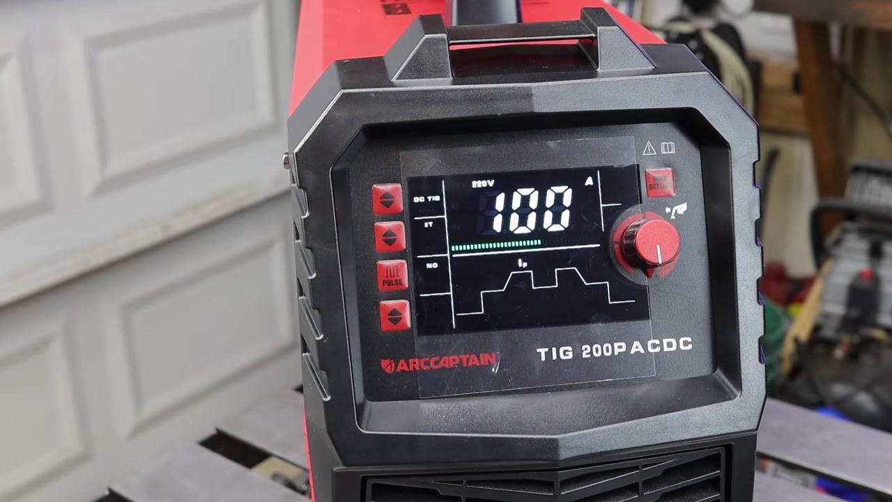
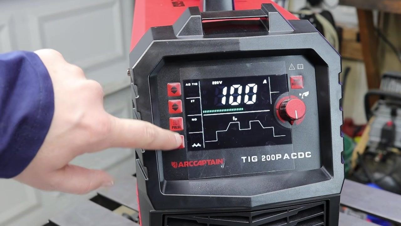
Examine the digital display and control panel on an advanced machine such as the ARCCAPTAIN TIG 200P ACDC, which shows voltage (220V), amperage (100A), mode indicators such as DC TIG and Pulse, a control knob, and multiple mode-selection buttons.
-
Identify additional adjustable settings available on advanced TIG welders, including pre-flow and post-flow (gas timing before and after welding), up-slope and down-slope (current ramping at start and end), and pulse mode with adjustable frequency.
Assemble the torch and configure polarity for welding
- Thread the collet body into the front end of the TIG torch until it is snug.
- Select the collet that matches the diameter of your tungsten electrode—for example, a 3/32" collet for 3/32" tungsten.
- Slide the tungsten electrode into the selected collet so that it fits securely.
- Insert the collet, with the tungsten in place, into the back portion of the torch. Use a short back cap for short tungsten or a long back cap for longer tungsten; either works, but a back cap is required. Thread the back cap onto the torch and tighten it—this action crimps the collet, securing the tungsten so it does not move.
- Select a ceramic cup with an opening size matching your welding needs. The number on the cup indicates the opening diameter in sixteenths of an inch (for example, a #5 cup has a 5/16" opening). Thread the cup onto the collet body until snug; do not overtighten.
- Adjust the tungsten stick-out to match the cup diameter—about 5/16" for a #5 cup. Loosen the back cap, set the tungsten to the desired length, then retighten the back cap.
- Attach the TIG torch lead to the negative terminal on the welder and attach the ground (earth) clamp to the positive terminal. This configuration is known as DCEN (Direct Current Electrode Negative) polarity.
- Note that many entry-level TIG welders use a scratch start method to initiate the arc.
- Turn on the welder and set the desired amperage for your welding job using the control knob and digital display—for example, set the amperage to 100A for typical steel welding. Use the mode buttons to select DC TIG, pulse, or other features as required, and confirm the voltage (for example, 220V), amperage, and selected mode on the display. Fine-tune additional parameters such as pre-flow, post-flow, up-slope, down-slope, AC balance, and pulse settings if your machine supports them.
Safety note: Double-check all connections and settings before beginning your weld. Proper assembly and setup are essential for safe and effective TIG welding.
Manage gas flow and arc starting on a TIG welder
- Understand that shielding gas enters the TIG welder from the back of the machine and travels through internal components before reaching the torch. This allows the machine to control gas timing automatically, so you do not need to manually adjust a valve for gas on/off—improving convenience and consistency during welding.
-
Recognize that activating the torch causes the machine to open a solenoid valve, starting gas flow synchronized with the welding process to ensure proper shielding at the right time, eliminating manual gas valve operation.
-
Hold the TIG torch and position the tungsten electrode close to the workpiece. Confirm the work area is clear and the metal is properly clamped or secured, with gloves and safety equipment ready.
-
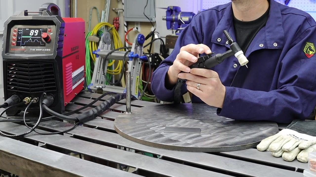
Move the tungsten electrode close to the workpiece without touching it, then pull the trigger or press the finger switch on the torch to start the arc. The machine automatically starts gas flow and initiates the arc using high-frequency ignition. Begin welding as soon as the arc is established.
-
As you pull the trigger, the arc ignites and welding begins. Maintain a steady hand and keep the torch at the correct angle for optimal results.
-
Understand that the solenoid inside the machine controls gas flow when you press the trigger. Holding the trigger keeps the gas flowing and the arc active; releasing the trigger stops the arc but allows gas to continue flowing briefly to shield the weld as it cools.
-
When you release the finger switch, the arc is extinguished. Keep the torch positioned over the weld until the post-flow gas stops to ensure the weld solidifies under shielding gas and prevents contamination.
-
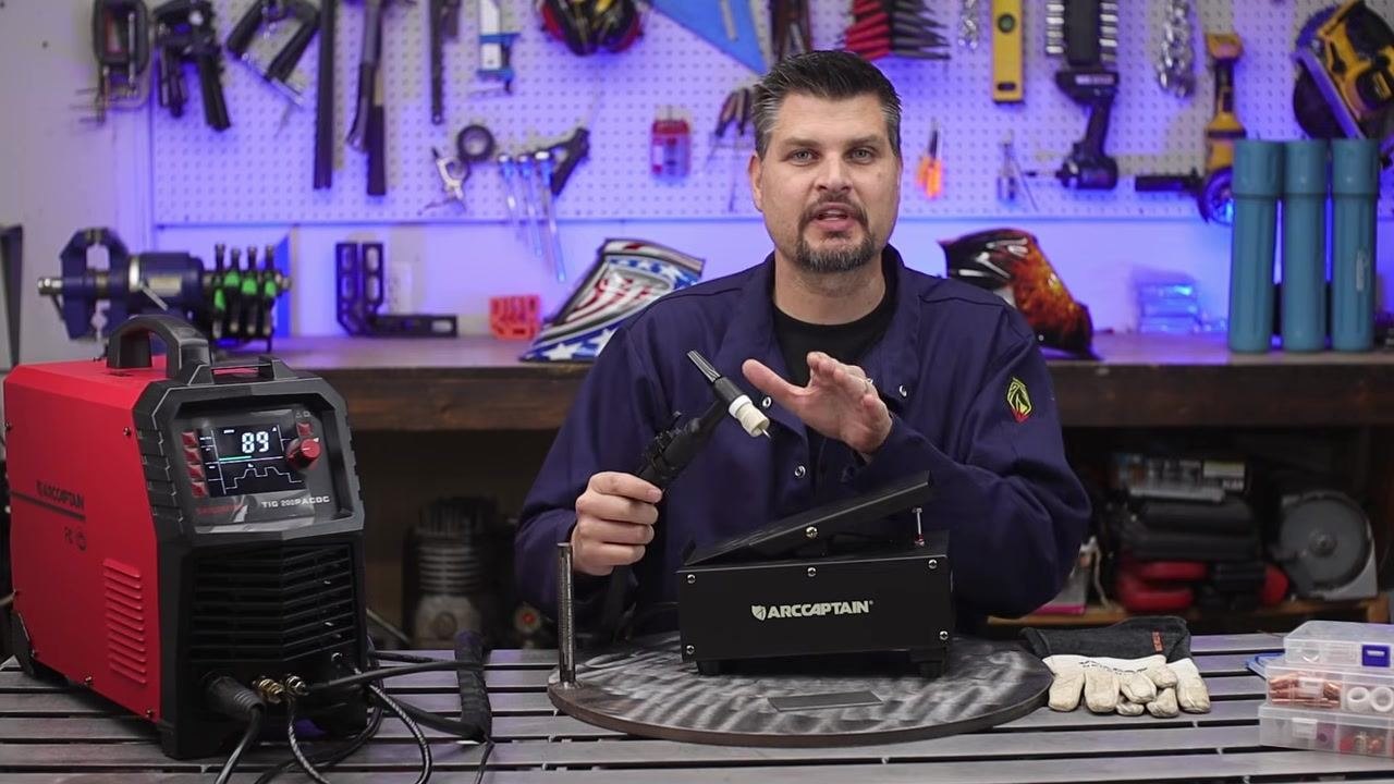
As an alternative to the finger switch, use a foot pedal to control the arc and gas flow. Pressing the pedal starts the arc and gas flow; releasing it stops both. The foot pedal provides more precise control over the welding process, especially for variable amperage.
-
Whether using a finger switch or foot pedal, pressing the control initiates high-frequency start and gas flow, while releasing it stops the arc and, after a short delay, stops the gas flow. This automated process ensures consistent shielding and ease of use.
Apply advanced TIG welding control and techniques
-
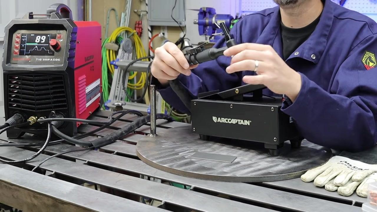
Understand foot pedal amperage control. On a machine such as the ARCCAPTAIN TIG welder, pressing the foot pedal down causes the machine to output amperage up to the maximum setting configured on the welder.
-
Press the foot pedal fully to achieve maximum heat output for starting the weld or when additional heat is needed. As you progress along the weld and notice the workpiece getting too hot, gradually ease off the pedal to reduce amperage and control heat input.
-
When the weld is complete or you need to stop, release the foot pedal to cut off amperage and extinguish the arc, allowing for clean weld terminations and consistent results.
-
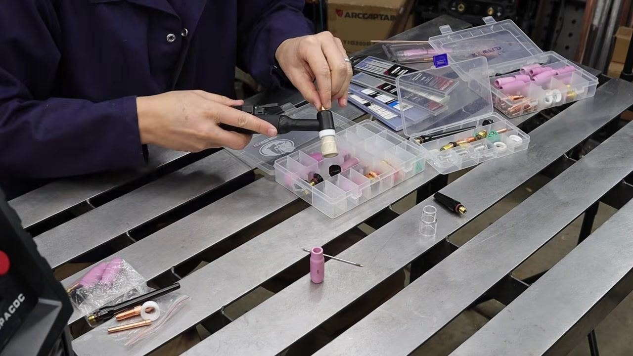
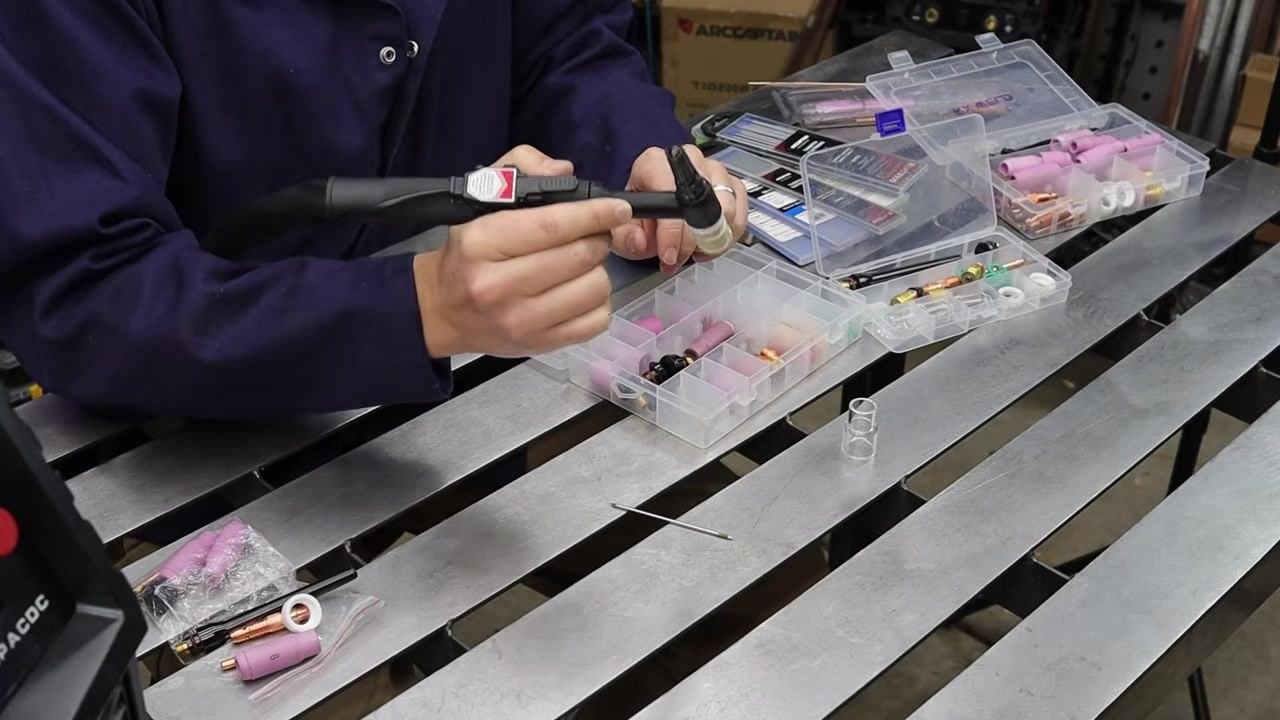
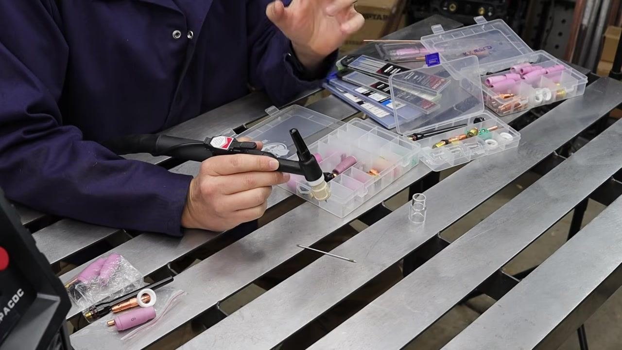
Consider upgrading to a stubby gas lens kit for improved torch control and visibility. Remove the standard cup from the TIG torch in preparation for installing the stubby gas lens.
-
Select the appropriate stubby gas lens components from the organizer box and install the stubby gas lens and cup onto the TIG torch, ensuring all parts are properly seated. The stubby kit makes the torch assembly shorter and more maneuverable.
-
Note that the stubby gas lens allows you to get the torch closer to the workpiece, improving control and visibility, and making it easier to see the tungsten electrode and weld puddle.
-
With the stubby gas lens installed, you can better see the tungsten and the weld area, allowing for more precise work.
-
Recognize that the stubby kit enables you to work much closer to the weld, offering better control compared to the standard, longer torch setup.
-
Apply basic TIG welding technique: hold the torch straight down at a slight angle to the workpiece for optimal arc control, and use your non-dominant hand to feed the filler rod steadily into the weld puddle.
-
Practice making small circles with the torch or keeping your hand as steady as possible to develop consistent weld beads.
Practice and review your setup
-
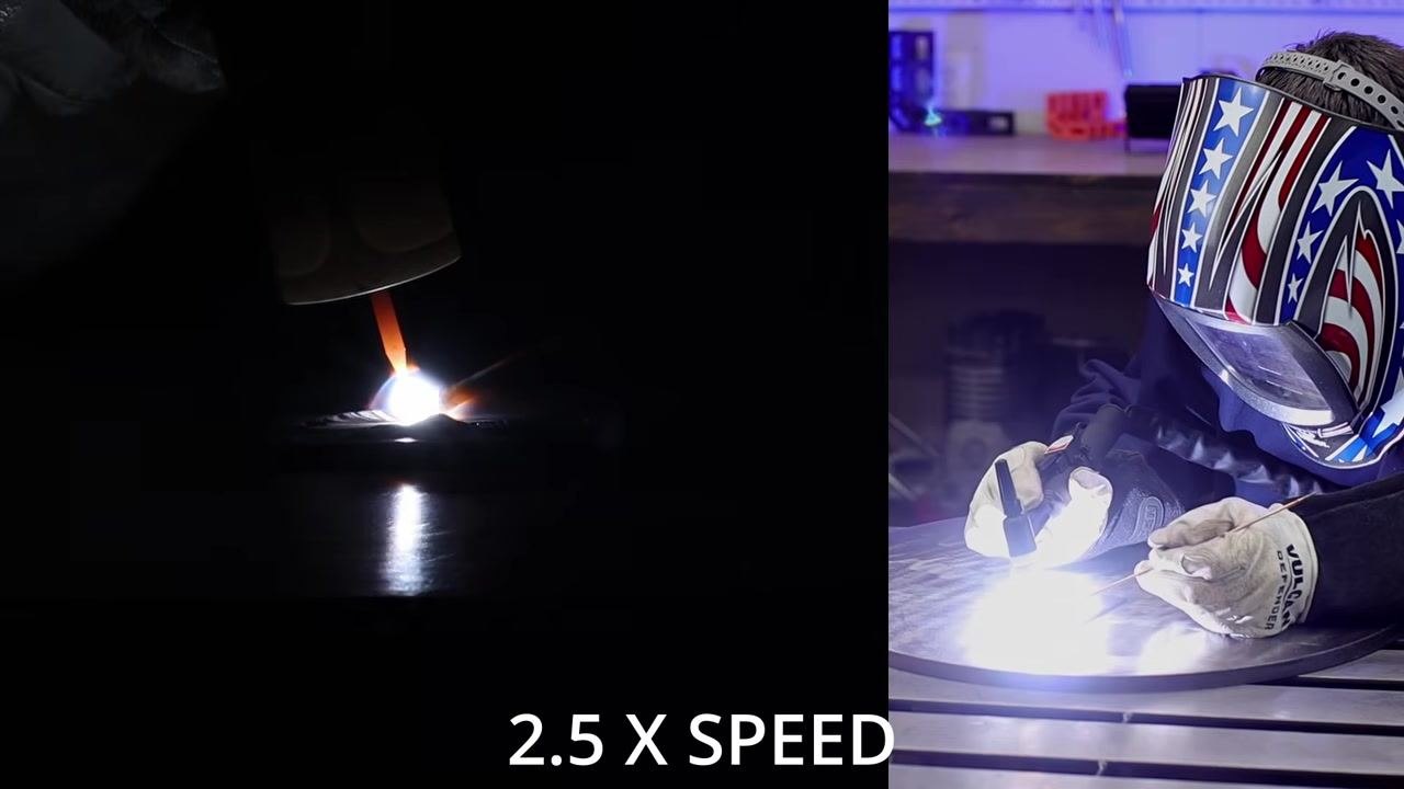
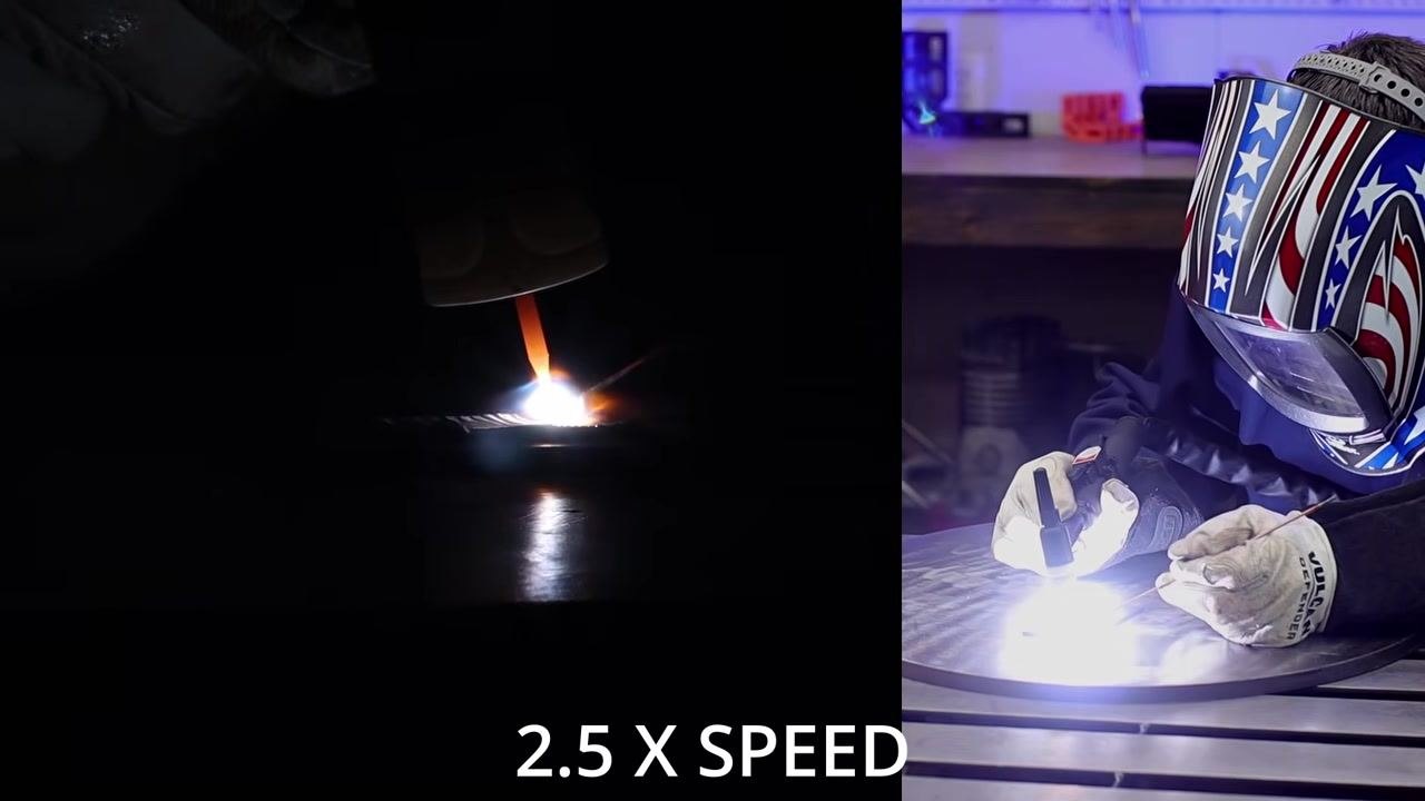
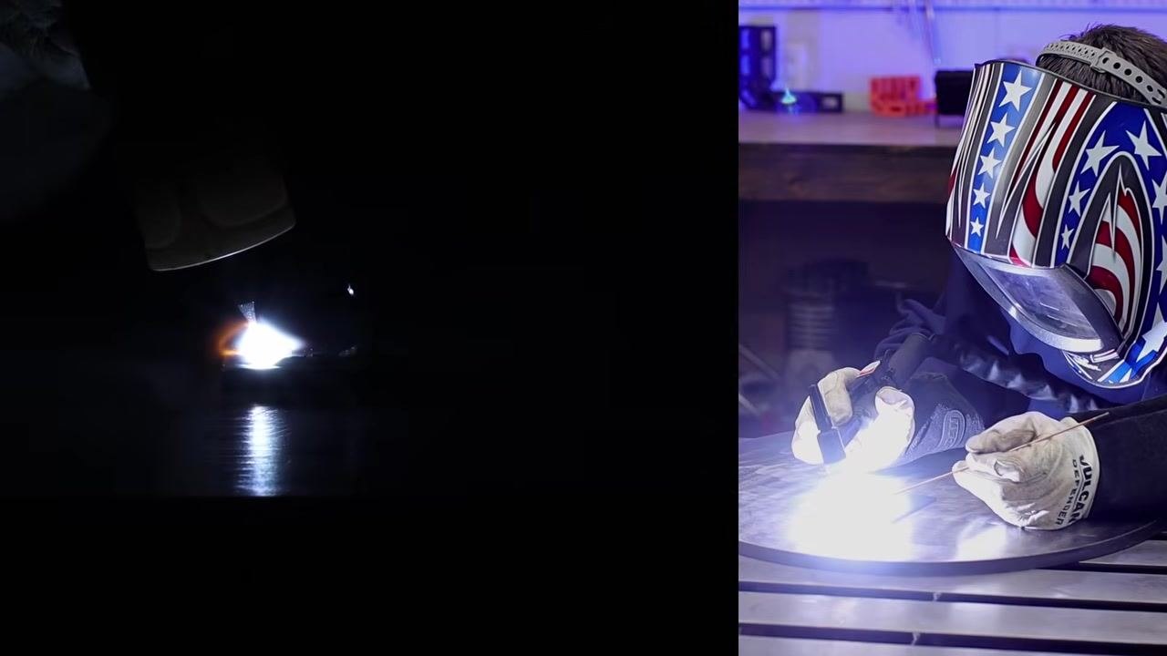
Continue practicing your TIG welding skills regularly to improve consistency and control. Footage of this practice is shown at 2.5x speed to emphasize the importance of repetition for skill development.
-
Consider the ARCCAPTAIN TIG welder as a strong introductory machine for beginners, offering a range of features and options suitable for learning and advancing your skills.
-
After practicing, review your equipment and workspace setup: confirm the welder display, TIG torch, gloves, and organizer boxes of accessories are laid out and accounted for, and keep your workspace organized with tools and helmets stored on a pegboard or similar system.
Verification and summary
Confirm the following before and after each welding session:
- Gas cylinder valve is fully closed after welding to prevent gas loss.
- Tungsten electrode type, size, and grind angle (15°–30°, axial) match your material and machine.
- Filler rod type and diameter (ER70S-2 for beginner steel work) match your material thickness.
- Torch components—cup, collet, collet body, and back cap—are assembled and tightened correctly, with tungsten stick-out matching the cup size.
- DINSE connector is correctly sized and securely seated in the negative terminal, with the ground clamp attached to the positive terminal (DCEN polarity).
- Welder amperage, mode, and any advanced settings (pre-flow, post-flow, up-slope, down-slope, pulse) are configured for your material and job.
- Helmet and gloves are worn throughout the welding process.
By following this procedure, you can manage gas flow and arc starting on a TIG welder, control heat with a finger switch or foot pedal, and apply consistent technique for steel welds. Reinforcing these steps through regular practice, understanding a feature-rich introductory TIG welder's controls, and maintaining an organized workspace will support safe and effective TIG welding sessions.
Generation details: cost, quality tiers
Docsie billed 7,000 credits ($4.90) to analyze this 14-minute video at standard quality. The rewrite, template fill and Word/PDF exports were included. The same video at each quality tier:
| Quality | Frames sampled | Credits | Approx. cost |
|---|---|---|---|
| Draft | every 16-30 s | 3,500 | $2.45 |
| Standard (this guide) | every 8-15 s | 7,000 | $4.90 |
| Detailed | every 4-7 s | 14,000 | $9.80 |
| Ultra | every 1-3 s | 28,000 | $19.60 |
Credits priced at $0.70 per 1,000; plans include a monthly allowance. Enterprise customers on on-premise or bring-your-own-model deployments run this on their own inference and pay no per-video credits.
Generated by Docsie Video-to-Docs on 2026-09-14 from a 13-minute video. Screenshots are frames from the source video and belong to their creator, DIY PRO, whose original is embedded above. If you own this video and want the guide removed or credited differently, contact us and we will act within one business day.