
How to Set Up a CNC Machine
This procedure describes how to set up a CNC machine (specifically a CNC lathe) for a new machining job. It covers gathering the required materials and tools, powering on the machine, homing the axes, loading a material, loading a CNC program, and preparing the tool position for a facing operation. Follow these steps in order to ensure a safe and accurate setup before machining begins.
Video: CNC lathe setup part 1 by Somers Tide (2012). All credit for the demonstration goes to the creator; watch the original on YouTube. The written guide below was generated from this video by Docsie. Creator? Request a change or removal.
Purpose
This procedure describes how to set up a CNC machine (specifically a CNC lathe) for a new machining job. It covers gathering the required materials and tools, powering on the machine, homing the axes, loading a material, loading a CNC program, and preparing the tool position for a facing operation. Follow these steps in order to ensure a safe and accurate setup before machining begins.
Scope
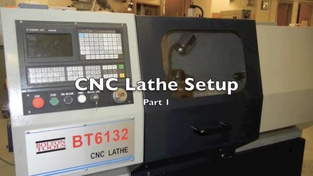
This SOP applies to operators preparing a CNC lathe (model BT6132 CNC LATHE with a GSK CNC controller) for a new part run. It covers the initial setup phase only, from powering on the machine through positioning the tool for facing. Tool setting and workpiece zeroing for the machining cycle itself are addressed in Part 2 of this documentation.
Required equipment/tools
Before beginning, gather the following items and lay them out on a clean, organized workspace:
- Part plans and setup steps documentation
- A piece of material cut several inches longer than your final part requires
- Dial caliper
- Micrometer
- 1/2 inch gauge block
- 0.001" (1-1000) thickness gauge
- Writing instrument (pen or pencil)
- Chuck key
Procedure
Power on the CNC lathe
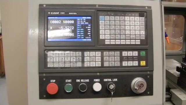
Locate the CNC lathe and identify its control panel, positioned on the left side of the machine. Find the red power button (dial) on the left side of the control panel and flip it to turn on the machine.
Boot the controller
Twist the red E-stop (emergency stop) button to release it, then press the green START button to boot the controller. Wait for the controller screen to power up and display the startup interface before continuing.
Perform machine zero (homing procedure)
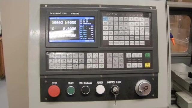
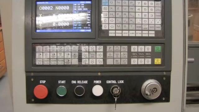
On the controller, locate and press the Machine Zero function. Home the X axis first by pressing the X-axis arrow button (downward-pointing arrow) and wait until all movement stops and the display reads X = 0.0000. Next, home the Z axis by pressing the Z-axis right arrow button; listen for machine movement and wait until the machine reaches its home position. Confirm that both axes read zero on the controller display before proceeding.
Prepare and insert the material
Ensure your material is cut several inches longer than the required finished part length. Insert the prepared material into the lathe chuck and secure it firmly, making sure it is properly aligned before continuing to the next step.
Set material length using the dial caliper
Determine the required extension length for your material. For a part approximately 2 inches long, set your dial indicator to 3 inches to allow extra length for facing and cutoff. Use the depth rod of the dial caliper to measure from the face of the lathe chuck to the end of the material, and adjust the material until the measured length is exactly 3 inches.
Lock the material in the chuck
Insert the chuck key into the chuck and tighten it to securely lock the material in place. Ensure the material is firmly held and properly aligned.
Safety note: Always remove the chuck key from the chuck immediately after tightening to prevent accidents.
Load the CNC program
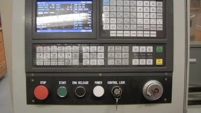
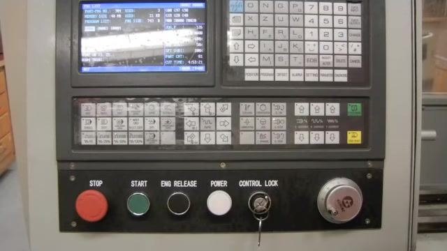
Press the PROGRAM button three times on the CNC controller to enter the Program List window. The current window is indicated in the top left corner of the screen.
Use the arrow keys to navigate and highlight the desired program file. In this example, select file O0002.
Once the correct file is highlighted, press the EOB (End of Block) key to load the selected program, and wait for the controller to confirm the program has loaded.
Clear previous workpiece coordinates
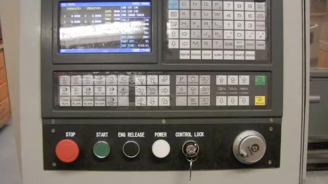
Press the PROGRAM button three more times to enter the Program State window. Follow the on-screen prompts or use the appropriate function to clear all previous workpiece coordinates, ensuring a fresh setup for the new part.
Move the tool carriage into position
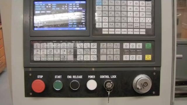
Press the MANUAL button on the controller to enable manual movement of the tool carriage. Use the X and Z axis arrow keys to move the tool carriage into position near the material, preparing for the next setup steps.
Clear all tool offsets and set the turret to tool 1
Ensure your tooling is a safe distance away from the material before proceeding. Verify you are in the Program State window, then press the MDI (Manual Data Input) key on the controller.
Enter the following command:
T0100 U0 W0
This command clears all tool offsets and prepares the turret for tool 1. Press the Data Input button to confirm the command, then press Cycle Start to execute it. Listen for the tool turret to rotate; if you are not already on tool number 1, the turret will automatically rotate to it.
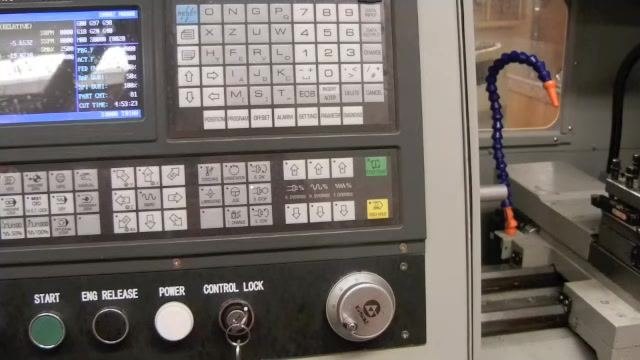
Prepare to set new tool and workpiece zero offsets
After clearing previous offsets, you must program new offsets for both the tool and the workpiece zero (00). Use the MPG (Manual Pulse Generator) hand wheel on the controller to do this. Press the MPG button to enable manual movement mode, select the desired axis (such as X), and select the movement increment (for example, x100). Rotate the MPG hand wheel to move the tool carriage, observing the carriage move on the left-hand side of the machine.
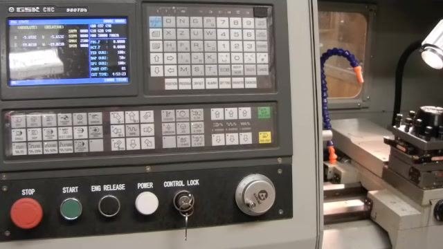
Fine-tune the tool position using the MPG hand wheel and movement increments
Press the Z axis button to enable movement of the carriage left and right. Select the movement increment as follows:
- x100 for coarse positioning, moving the carriage quickly to a rough position
- x10 for fine positioning, where each click of the MPG hand wheel moves the carriage by 0.001 inches for precise adjustments
Safety note: Never press x1000. This setting moves the carriage extremely rapidly and can cause overtravel or damage.
Begin with x100 to bring the tool close to the desired position, then switch to x10 to make fine adjustments and accurately set the tool position.
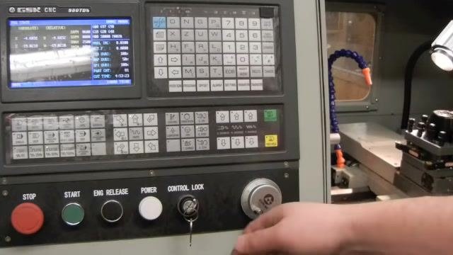
Prepare to face the workpiece
Once the tool is positioned accurately using the MPG hand wheel and the appropriate increment settings, prepare to face the part. Confirm the tool is aligned and ready for the facing operation, and double-check all settings and tool positions before proceeding with the machining operation.
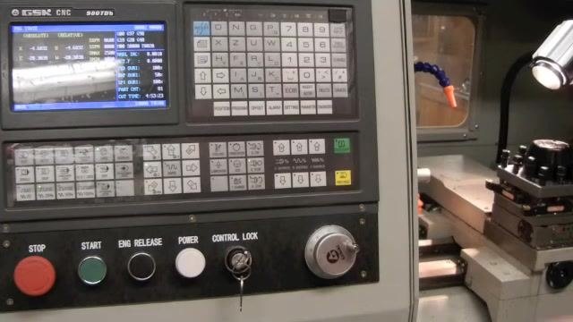
Verification and summary
Before moving on to the machining operation, confirm the following:
- The machine has been homed and both the X and Z axes read zero.
- The material is securely locked in the chuck and the chuck key has been removed.
- The correct CNC program (
O0002in this example) is loaded and previous workpiece coordinates have been cleared. - The tool turret is set to tool 1 with offsets cleared.
- The tool carriage has been positioned using the MPG hand wheel, using x100 for coarse movement and x10 for fine adjustment, and never x1000.
What's next
This concludes Part 1 of the CNC lathe setup process. Continue to Part 2 of this documentation for tool setting, workpiece zeroing, and the facing operation itself.
Generation details: cost, quality tiers
Docsie billed 3,000 credits ($2.10) to analyze this 6-minute video at standard quality. The rewrite, template fill and Word/PDF exports were included. The same video at each quality tier:
| Quality | Frames sampled | Credits | Approx. cost |
|---|---|---|---|
| Draft | every 16-30 s | 1,500 | $1.05 |
| Standard (this guide) | every 8-15 s | 3,000 | $2.10 |
| Detailed | every 4-7 s | 6,000 | $4.20 |
| Ultra | every 1-3 s | 12,000 | $8.40 |
Credits priced at $0.70 per 1,000; plans include a monthly allowance. Enterprise customers on on-premise or bring-your-own-model deployments run this on their own inference and pay no per-video credits.
Generated by Docsie Video-to-Docs on 2026-09-14 from a 5-minute video. Screenshots are frames from the source video and belong to their creator, Somers Tide, whose original is embedded above. If you own this video and want the guide removed or credited differently, contact us and we will act within one business day.