
How to Set a Work Offset on a CNC Machine
This document explains how to set a work offset on a CNC machine using a 3-axis Doosan vertical mill with a Fanuc I-Series control. It covers aligning the vise with the machine's X-axis, loading and securing the workpiece, establishing X and Y zero points with an electronic edge finder, and transferring those coordinates into the work offset table (G54, G55, etc.). Following this procedure ensures accurate and repeatable part positioning for machining operations.
Video: SETTING A WORK OFFSET ON A CNC MILL by Tom Stikkelman (2016). All credit for the demonstration goes to the creator; watch the original on YouTube. The written guide below was generated from this video by Docsie. Creator? Request a change or removal.
This document explains how to set a work offset on a CNC machine using a 3-axis Doosan vertical mill with a Fanuc I-Series control. It covers aligning the vise with the machine's X-axis, loading and securing the workpiece, establishing X and Y zero points with an electronic edge finder, and transferring those coordinates into the work offset table (G54, G55, etc.). Following this procedure ensures accurate and repeatable part positioning for machining operations.
Purpose
This procedure standardizes the method for indicating a vise, loading a part, and setting work offsets so that CNC programs run against a consistent and accurate work origin.
Scope
This procedure applies to operators setting up a workpiece and establishing work coordinate offsets on a 3-axis vertical mill with a Fanuc I-Series control. It covers vise alignment, part loading, edge finder use, and entry of offset values into the control.
Required equipment and PPE
- 3-axis Doosan vertical mill with Fanuc I-Series control
- Kurt vise securely mounted on the machine table
- Dial indicator (Starrett or equivalent) with mounting fixture
- Brass hammer
- Parallels
- Electronic edge finder with a 0.400" diameter ball
- Work gloves
Verify machine and vise setup
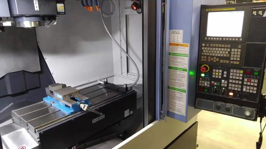
Confirm you are working on a 3-axis Doosan vertical mill equipped with a Fanuc I-Series control. Verify the vise is securely mounted on the machine table. Power on the machine and confirm the work area is clear before proceeding.
Check and indicate the vise jaw alignment
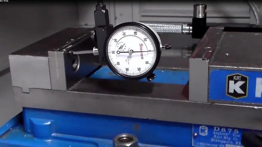
Confirm that the solid jaw of the vise is intended to align with the machine's X-axis. Mount a dial indicator so its tip contacts the solid jaw, then sweep the indicator from one end of the jaw to the other and note any taper. In this example, the reading was approximately 0.038" (38 thousandths).
If the indicator shows a taper, identify which end of the vise needs to move. In this example, the end with the higher reading needed to move toward the operator.
Zero the indicator and prepare for adjustment
Return the indicator to the starting corner and zero the dial. Tighten the bolt on the far side of the vise so it acts as a pivot point, then loosen the bolt on the near side to allow adjustment.
Tap the vise for alignment
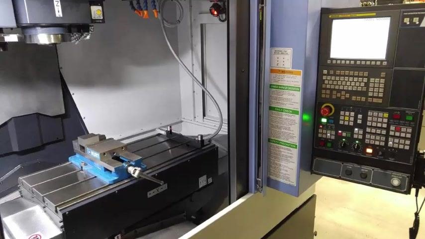
Use a brass hammer to gently tap the vise on the loosened side, moving it slightly to correct the taper. Aim to move the vise just past the previously measured error to compensate for backlash.
After tapping, sweep the indicator across the jaw again and repeat the tapping and checking process until the taper is minimized.
Tighten the vise bolts
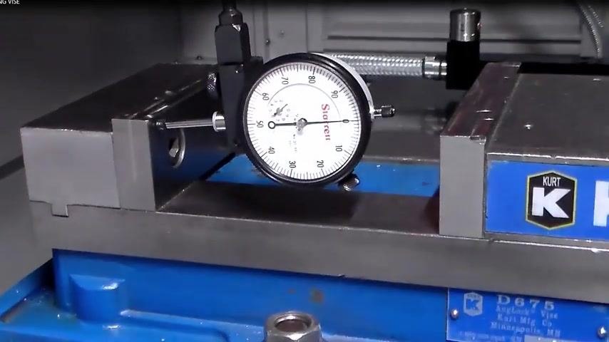
Once the indicator shows minimal or zero taper (in this example, the reading dropped from 0.008" to zero), tighten both vise bolts securely to lock the vise in place.
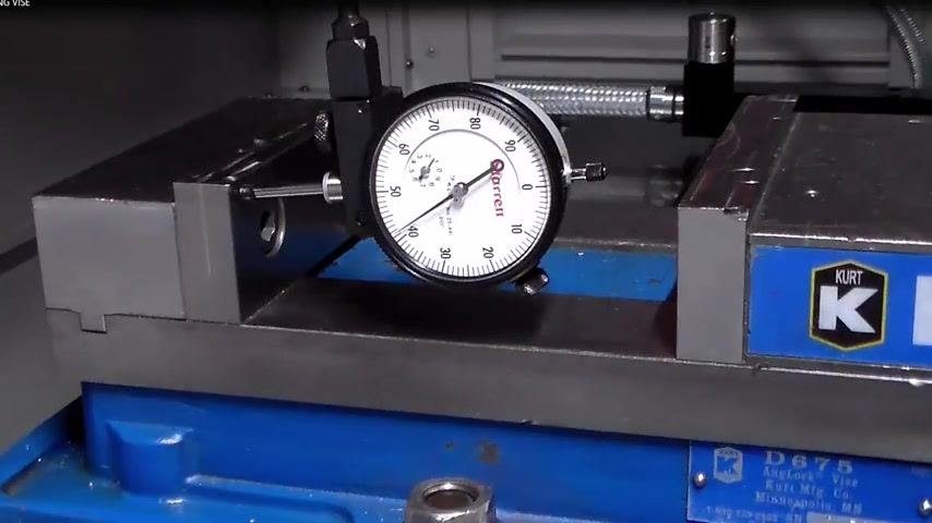
Perform a final check of vise alignment
Zero the dial indicator at the starting position on the solid jaw. Make one final pass across the jaw to confirm the vise remained straight after tightening. The reading should stay at zero or within acceptable tolerance, confirming the vise did not shift during tightening.
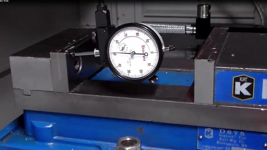
Insert parallels
Open the vise jaws to create a gap slightly larger than the part. Place one parallel in the back of the vise against the solid jaw, and place a second parallel on the front side of the vise.
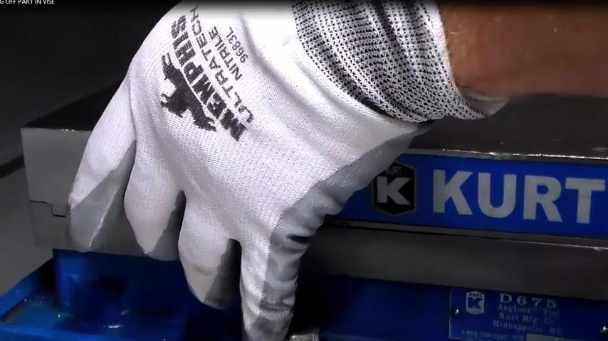
Load the part into the vise
Lay the workpiece between the parallels inside the vise. Align the part with the left side of the solid jaw to ensure proper positioning.
Secure the workpiece
Hold the part down firmly so it sits flat on the parallels, then tighten the vise handle to clamp the part securely in place.
Position the part for edge finder use
Obtain an electronic edge finder with a 0.400" (400 thousandths) diameter ball. The edge finder illuminates when it makes contact with metal. Use the left side of the part to set the X-axis zero and the front side to set the Y-axis zero. The left edge is used for X because it was previously indicated and is known to be straight.
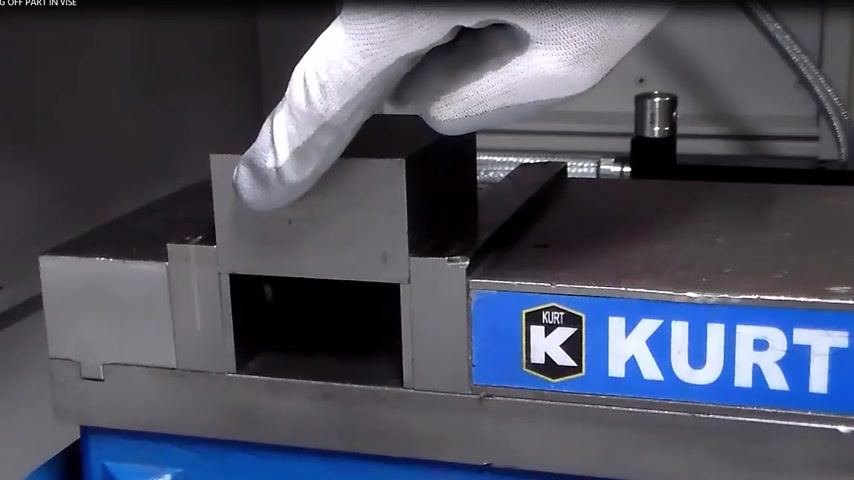
Approach the left side of the part with the edge finder
Lower the electronic edge finder toward the left side of the workpiece. Move it in the X-axis direction until the ball makes contact with the part; the edge finder will light up and buzz when contact is made.
Safety note: After the edge finder lights up, move straight up in Z to break contact without moving the X-axis.
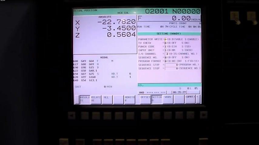
Select the Position and Relative pages
On the CNC control panel, select the Position page, then switch to the Relative page to view the current axis positions.
Zero the X-axis
Click on the X-axis value on the control screen, then click the Origin button to zero the X-axis at the current position.
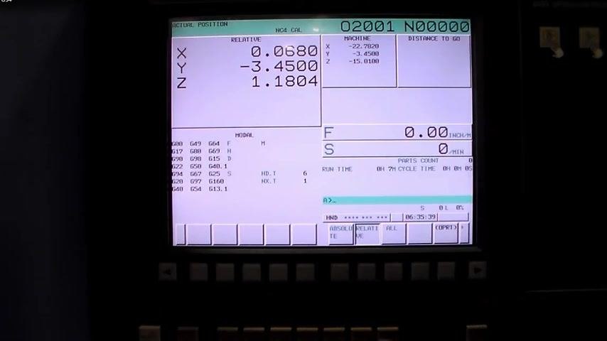
Move the X-axis +0.2000" (200 thousandths)
Use the hand control to move the X-axis exactly +0.2000" in the plus direction. This positions the centerline of the 0.400" edge finder ball directly over the edge of the part.
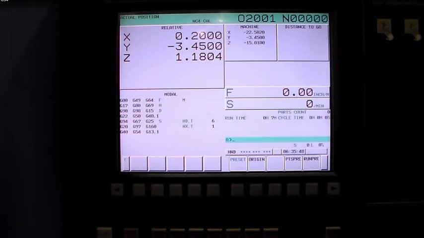
Zero the X-axis again
With the X-axis at +0.2000", click the X-axis value and then click Origin to zero it again. The X-axis is now correctly set with the center of the edge finder ball aligned to the left edge of the part.
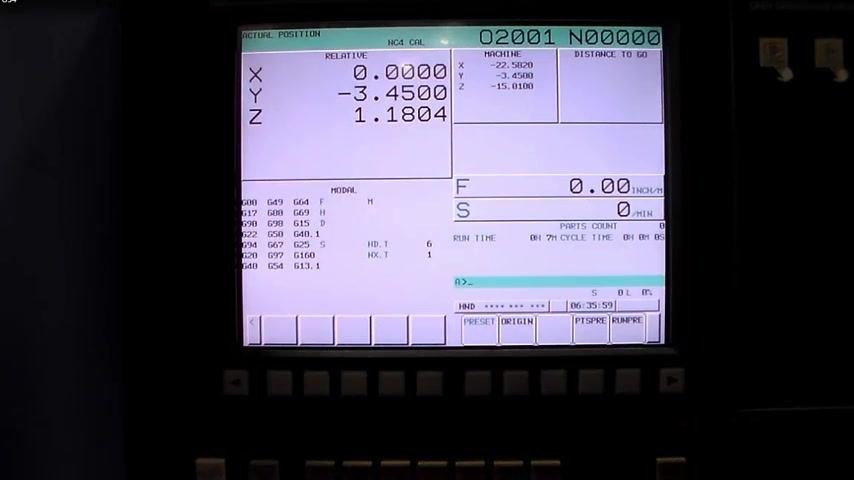
Move the edge finder to the front side of the part
Move the edge finder to the front (near) side of the part. Lower it in Z just enough so the ball sits below the top surface of the part, then approach the part in the Y-axis direction until the edge finder lights up and buzzes, indicating contact.
Safety note: After contact, move straight up in Z to break contact, ensuring the Y-axis does not move.
Zero the Y-axis
On the CNC control, click the Y-axis value, then click the Origin button to zero the Y-axis at the current position.
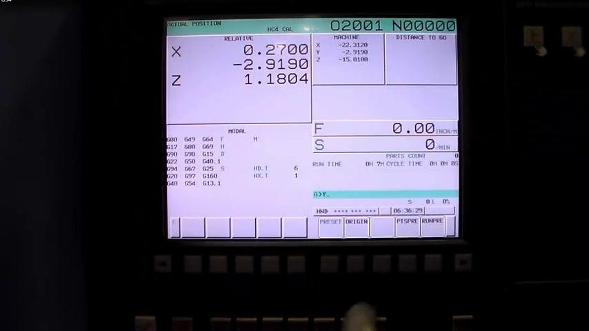
Move the Y-axis -0.2000" (minus direction)
Use the hand control to move the Y-axis exactly -0.2000". This positions the centerline of the edge finder ball directly over the front edge of the part.
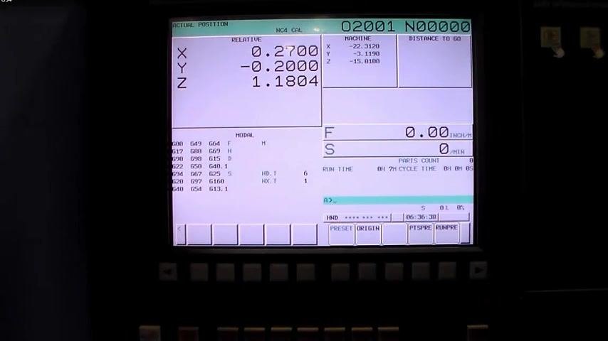
Zero the Y-axis again and return X to stored zero
With the Y-axis at -0.2000", click the Y-axis value and then click Origin to zero it again. The Y-axis is now correctly set with the center of the edge finder ball aligned to the front edge of the part. Move the X-axis back to the zero position stored earlier; the edge finder ball is now positioned at the intersection of X0 and Y0, marking the precise work origin for the part.
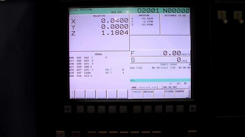
Move the X-axis +0.1000" on the relative position page
Move the X-axis to +0.1000" on the relative position page. Confirm the X value reads 0.1000, Y remains 0.0000, and Z is unchanged. The screen displays the current relative positions for X, Y, and Z, as well as machine and absolute positions.
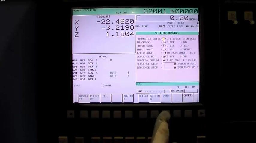
Move the Y-axis -0.1000" on the relative position page
Move the Y-axis to -0.1000" on the relative position page. Confirm the X value is 0.1000, Y is -0.1000, and Z remains unchanged. The display updates to show the new relative positions.
Access the machine position for work offset storage
Use the relative page to note the current location in X and Y, then switch to the machine position page to prepare for storing these values in the work offset. The screen now shows absolute positions: X = -22.4820, Y = -3.2190, Z = 1.1804.
Navigate to the work coordinates (G54) page
Select the WORK or OFFSET button to access the work coordinates page. The screen displays the G54 work coordinate fields for X, Y, and Z, all initially set to 0.0000, with the current machine positions visible in the upper section.
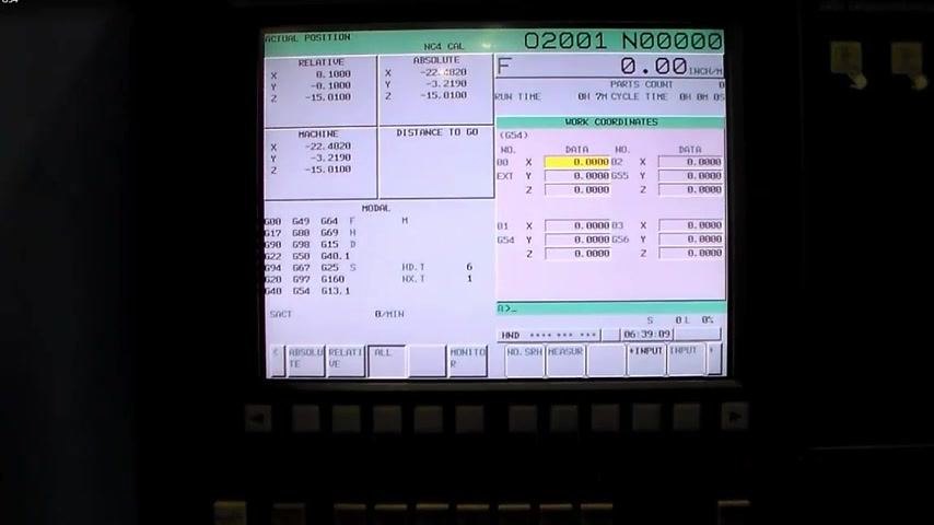
Transfer the X machine position to G54
Enter the current machine X position (-22.4820) into the G54 X field. Confirm that the field now displays -22.4820.
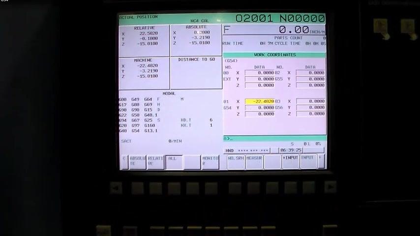
Transfer the Y machine position to G54
Enter the current machine Y position (-3.2190) into the G54 Y field. Confirm that the field now displays -3.2190.
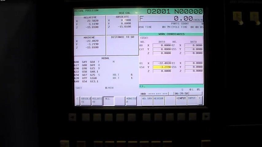
Repeat for additional work offsets (G55, G56, etc.)
Use the same process to set X and Y positions for G55, G56, G57, G58, and G59. Page down to access additional work offset fields as needed.
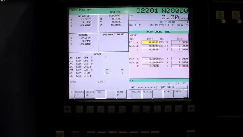
Understand the machine zero row
Observe the WORK COORDINATES section on the control screen. Note the row labeled "EXT" (sometimes called "Machine Zero") for X, Y, and Z axes. This row is typically at the top of the work coordinates table and is highlighted or separated from the individual G54, G55, etc., offsets.
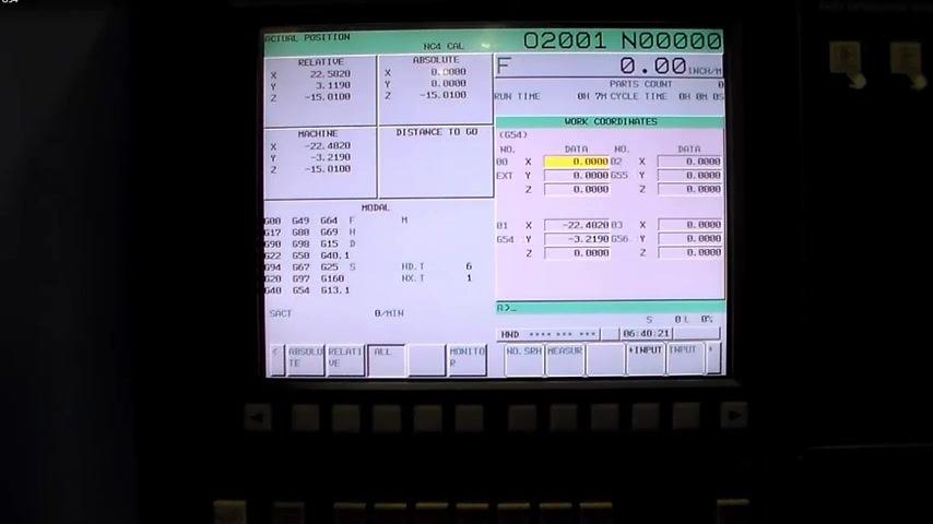
Exercise caution when entering values in machine zero
Safety note: Any value entered in the EXT (machine zero) row for X, Y, or Z affects all work offsets (G54, G55, G56, etc.). Always keep this row at zero unless you have a specific, advanced reason for changing it. Accidental changes here can shift all programmed work positions.
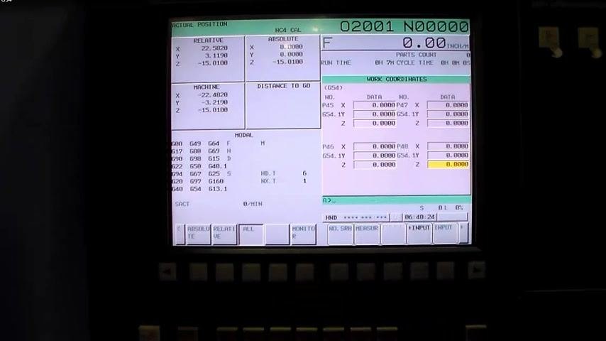
Verify machine zero values remain at zero
Before running any program, double-check that the EXT (machine zero) values for X, Y, and Z are set to 0.0000. Only modify these values if you have advanced knowledge and a specific requirement for global offsetting.
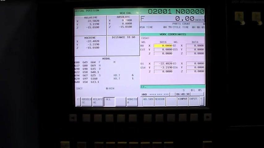
Verification and summary
Before starting machining operations, review the following:
- Vise indicated to the X-axis with a final reading of zero taper.
- Part loaded on parallels, aligned to the left side of the solid jaw, and clamped securely.
- X-axis zero set using the left side of the part; Y-axis zero set using the front side, both with the 0.400" edge finder ball.
- Machine X and Y positions transferred correctly into the G54 (and additional G55–G59, as needed) work offset fields.
- EXT (machine zero) row confirmed at 0.0000 for X, Y, and Z.
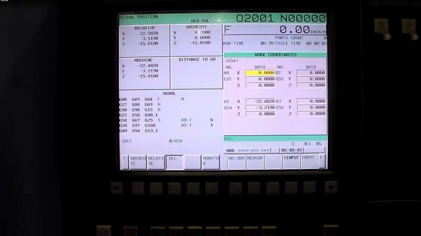
Confirming these values ensures safe, accurate, and repeatable CNC machining operations for the workpiece.
Generation details: cost, quality tiers
Docsie billed 4,000 credits ($2.80) to analyze this 8-minute video at standard quality. The rewrite, template fill and Word/PDF exports were included. The same video at each quality tier:
| Quality | Frames sampled | Credits | Approx. cost |
|---|---|---|---|
| Draft | every 16-30 s | 2,000 | $1.40 |
| Standard (this guide) | every 8-15 s | 4,000 | $2.80 |
| Detailed | every 4-7 s | 8,000 | $5.60 |
| Ultra | every 1-3 s | 16,000 | $11.20 |
Credits priced at $0.70 per 1,000; plans include a monthly allowance. Enterprise customers on on-premise or bring-your-own-model deployments run this on their own inference and pay no per-video credits.
Generated by Docsie Video-to-Docs on 2026-09-14 from a 7-minute video. Screenshots are frames from the source video and belong to their creator, Tom Stikkelman, whose original is embedded above. If you own this video and want the guide removed or credited differently, contact us and we will act within one business day.