
How to Flux Core Weld
This standard operating procedure explains how to flux core weld with consistent, clean results. It walks through evaluating existing welds, adjusting hand control, gun distance, travel speed, gun angle, and slag removal so that you can identify defects and correct your technique. The procedure is written for casual or beginner welders who are using flux core wire on projects such as wrought iron framework.
Video: Learn Perfect Flux Core Welds In 10 Mins | Gasless Flux Core Welding For Beginners Tips And Tricks | by NightWrencher (2021). All credit for the demonstration goes to the creator; watch the original on YouTube. The written guide below was generated from this video by Docsie. Creator? Request a change or removal.
This standard operating procedure explains how to flux core weld with consistent, clean results. It walks through evaluating existing welds, adjusting hand control, gun distance, travel speed, gun angle, and slag removal so that you can identify defects and correct your technique. The procedure is written for casual or beginner welders who are using flux core wire on projects such as wrought iron framework.
Purpose
The purpose of this procedure is to help you understand why flux core welds can vary in appearance and strength even when performed on the same machine with identical settings, and to give you a repeatable method for diagnosing and correcting common defects such as spatter, poor fusion, porosity, and excessive slag.
Scope
This procedure applies to flux core welding performed with a MIG-style gun setup, including machines such as the VULCAN ProTIG 220 and comparable units. It covers weld evaluation, gun distance and stick-out, travel speed, gun angle, slag formation and removal, and spatter prevention.
Required equipment and PPE
- MIG welder set up for flux core wire (e.g., VULCAN ProTIG 220 or comparable unit)
- Welding gloves
- Welding helmet
- Chipping hammer or wire brush for slag removal
- Anti-spatter spray
- Protective clothing such as a mechanic or denim jacket to shield skin from heat and UV exposure
- Workbench or stable work surface
- Metal workpieces (e.g., wrought iron bars) for practice welds
Step-by-step procedure
Set up your welding environment
Work in a workshop or garage setting with your metal framework laid out on a workbench. Confirm your welding machine is ready and that your safety equipment, including gloves and a helmet, is in place before you begin.
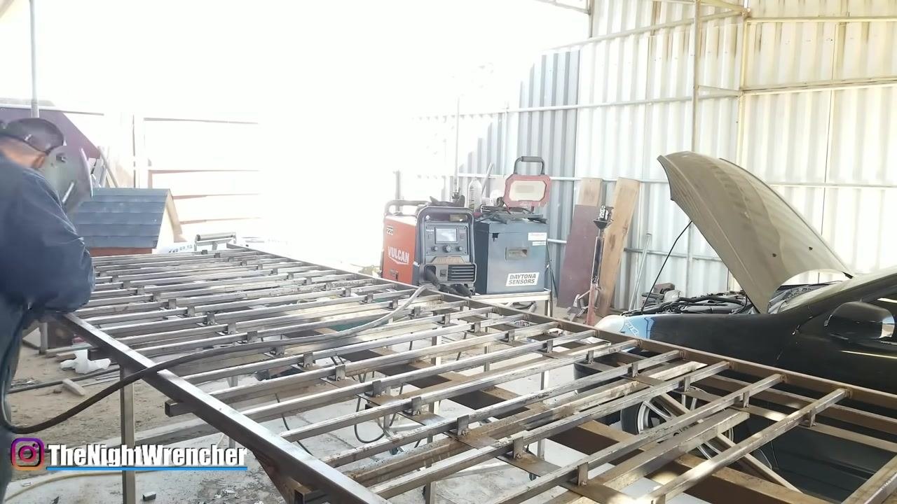
Compare an uneven weld to a smoother one
Before you start welding, look at examples of both rough and smooth welds so you know what to aim for. A rough weld looks uneven and spattered, while a smoother weld looks uniform along its length.
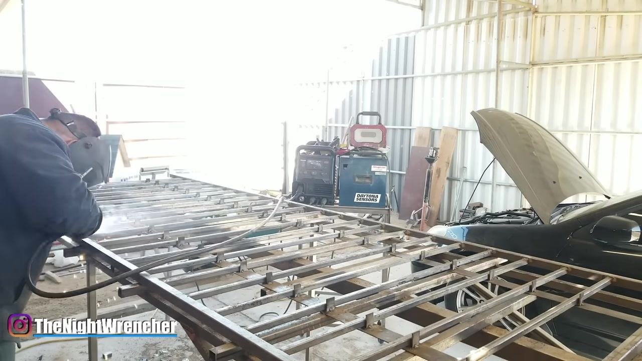
Review a full set of sample welds
Lay out a metal sample containing several distinct welds performed on the same machine, with identical settings, and in quick succession with no cooling time between them. Even under these identical conditions, the welds can look very different from one another, which shows that hand control—not machine settings—is the main variable affecting appearance.
Check gun distance on a rough weld
Point the MIG gun at a weld that came out poorly and check whether it was held too far from the workpiece. Holding the gun too far away is a common cause of poor weld quality.
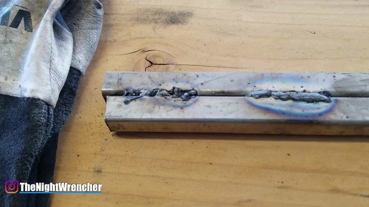
Simulate excessive wire speed
Move the MIG gun forward and back while welding to reproduce the effect of too fast a wire speed. With excessive wire speed, the wire does not have enough time to burn up and flow into the weld pool, and the gun is pushed back by the wire, causing the arc to repeatedly break and restart. Each break-and-restart cycle cools the wire and weld puddle, forcing you to reheat the puddle from zero, which produces a weld bead covered in small, round "balls" (globules) and significant spatter around the weld area.
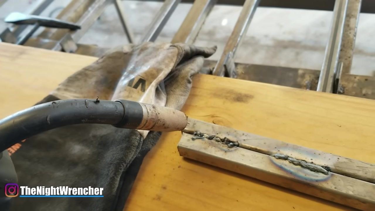
Identify wire protruding from the bead
Check for unmelted wire protruding from the weld bead. If the gun is held too far from the workpiece—approximately six inches or more—the wire can become extremely hot and break off before it melts into the weld, further degrading weld quality.
Safety note: Repeated arc interruptions and excessive spatter indicate an unstable arc and poor fusion; do not continue welding at this distance.
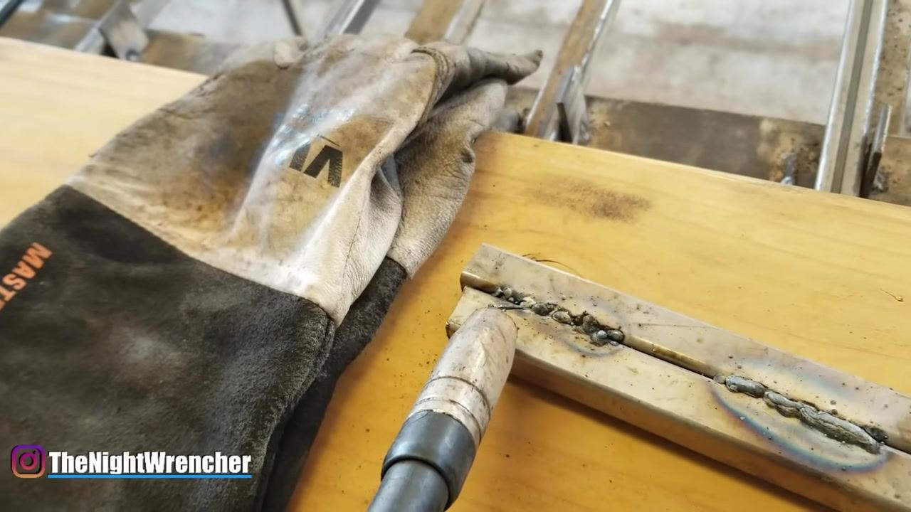
Correct wire speed while holding a steady distance
Hold the MIG gun at a consistent height—about six inches in this demonstration—and maintain a steady hand while setting the wire speed to a more appropriate, consistent value. Move the gun smoothly along the joint so the wire flows out and melts properly. Note that the weld may still lack sufficient heat for optimal fusion if the gun remains too far away, even though the resulting bead is more uniform than one produced with excessive wire speed.
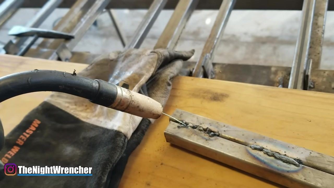
Compare the two corrected weld results
Examine the welds side by side: the first weld (excessive wire speed, improper distance) is rough with many balls and heavy spatter, while the second weld (consistent wire speed, steady hand, but still too far from the workpiece) is more uniform but lacks proper fusion and smoothness. Both wire speed and gun distance are critical for achieving a clean, strong weld.
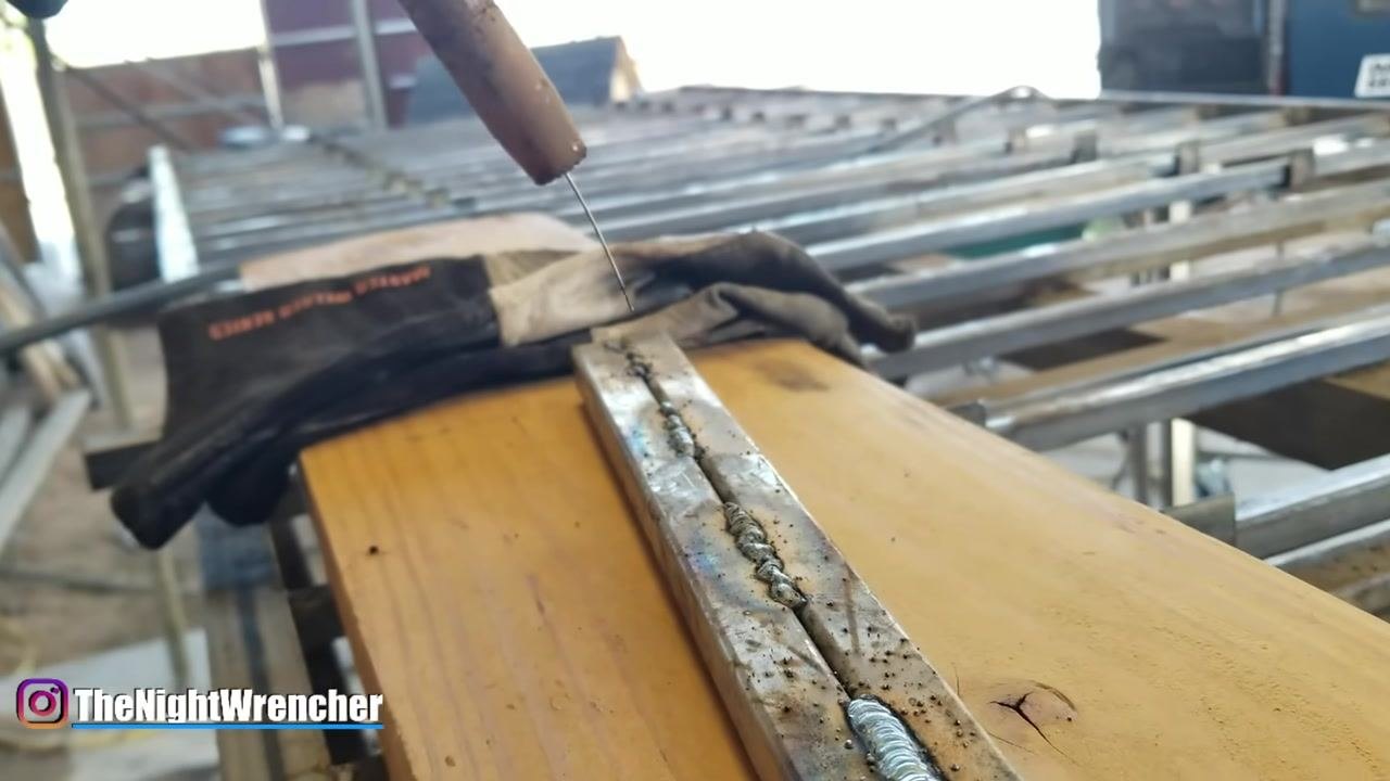
Move the gun closer to the workpiece
Move the MIG gun as close to the workpiece as possible without letting the tip touch the material. If the tip contacts the metal, it can weld to the workpiece, causing movement issues and other problems. Maintain a distance where the weld puddle flows out smoothly, but not so far that weld quality suffers.
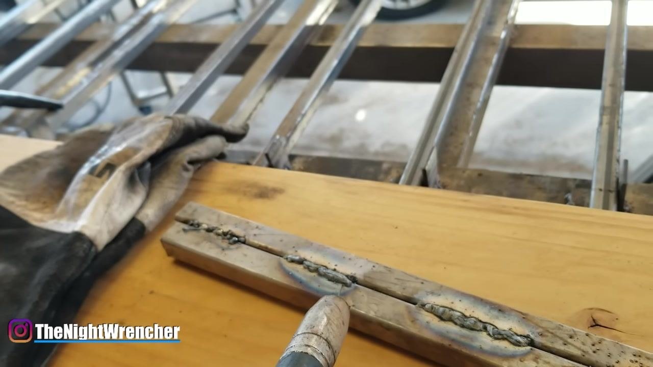
Maintain proper stick-out
Aim for a stick-out—the length of wire extending from the tip—of about half an inch to three-quarters of an inch. Stick-out is generally instinctive and not measured precisely while welding, so use this range as a rule of thumb. If the gun is about two inches away, you are too far and should move closer.
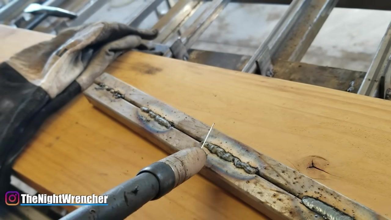
Compare welds made at different travel speeds
Observe two welds made at the same settings and gun height but with different travel speeds. The only difference between them is how quickly the gun was moved; the weld performed at a faster speed can look less ideal and have poorer penetration.
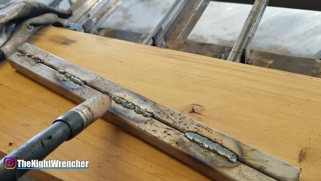
Avoid moving the gun too quickly
Do not move the gun too fast out of fear of burning through the material or making a hole. Moving too fast results in a weld that does not look right and lacks proper penetration. If both welds were subjected to a break test, the slower, properly penetrated weld would hold better than the faster, shallow weld.
Safety note: Keep the MIG gun close to the workpiece but never let the tip touch the metal; use a stick-out of about 1/2" to 3/4" and a steady, moderate travel speed for good penetration.
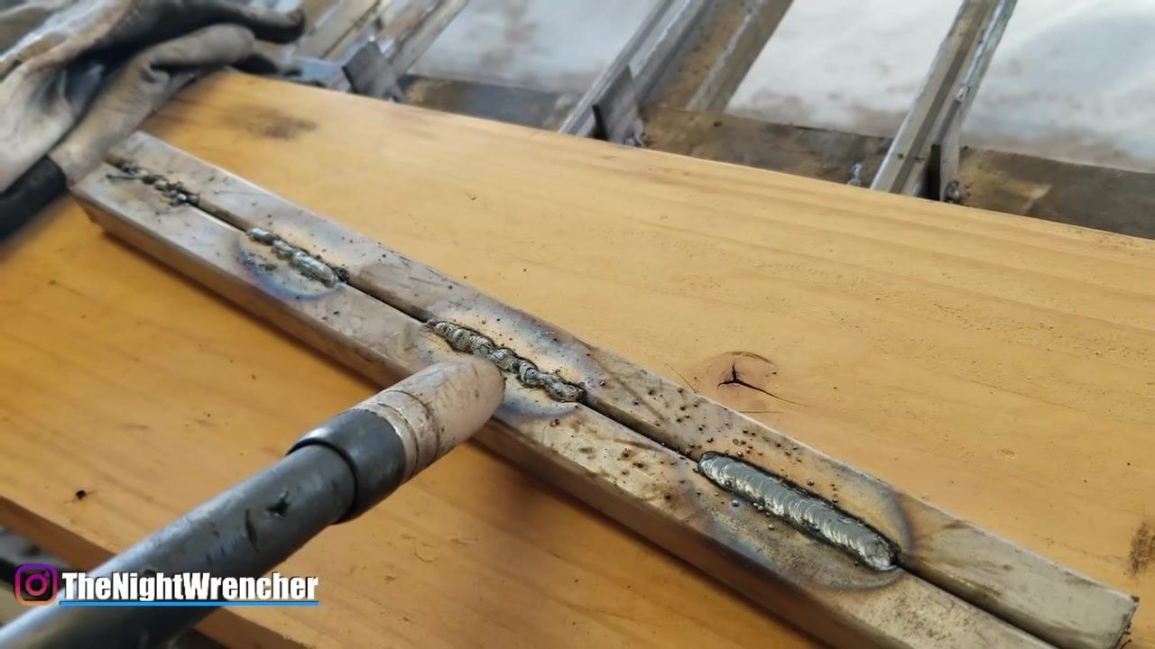
Continue practicing and observing your welds
As you practice, examine each weld bead for consistency, penetration, and overall appearance. Use the welding torch to apply heat and filler material to the metal pieces, and observe the results closely.
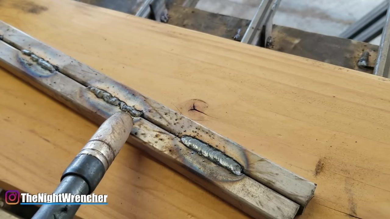
Recognize setup limitations as your welds improve
As your welds improve, you may notice limitations in your current setup or technique, such as excessive heat exposure to yourself or your workspace. This is a normal part of the learning process.
Safety note: The more heat you apply, the more you expose yourself to potential discomfort or hazards; use protective gear at all times.
Protect yourself from heat exposure
Be aware that prolonged welding sessions can cause sunburn, especially on exposed skin such as the inside of your arms. Consider wearing protective clothing such as a mechanic or denim jacket to shield yourself from UV and heat.
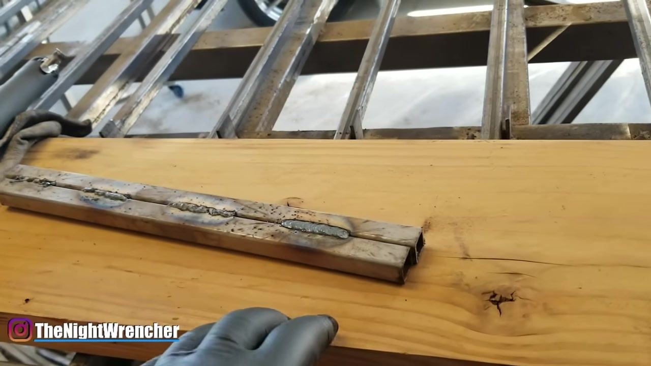
Keep your gear organized and accessible
Place your welding torch and gloves in a safe, accessible location when not in use so you can retrieve them quickly during your session.
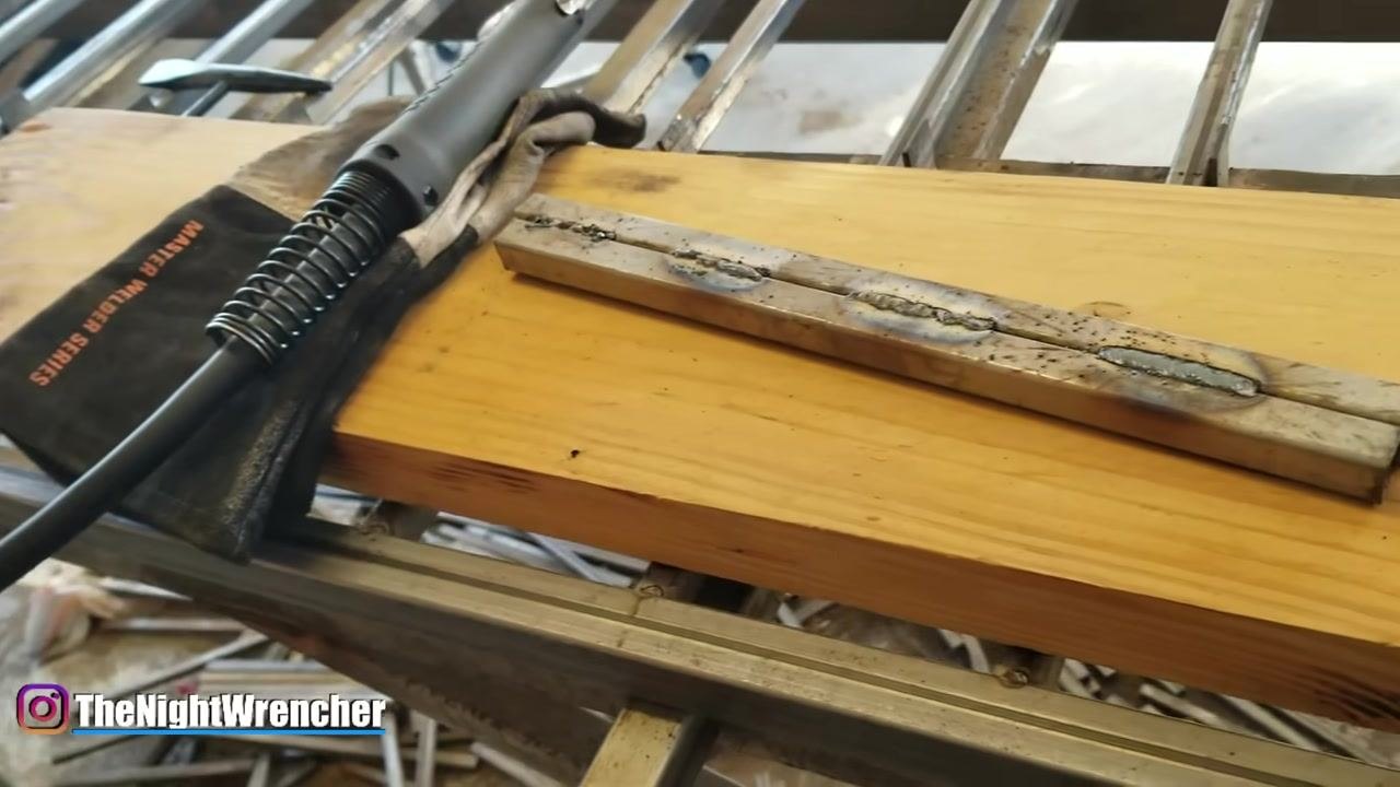
Inspect the weld bead for fusion and penetration
Check whether the weld bead has fused properly with the base material or is simply sitting on top of it. If the bead sits on top without fusing, you are not adding enough material or heat.
Identify welds likely to fail
Look for poorly fused welds or those with insufficient penetration, as these will not hold under stress. Visually inspect for cracks, gaps, or uneven bead formation.
Confirm proper heat and material application
Ensure that the filler material is melting and fusing with the base metal rather than just sitting on top of it. Adjust your technique as needed to achieve proper fusion.
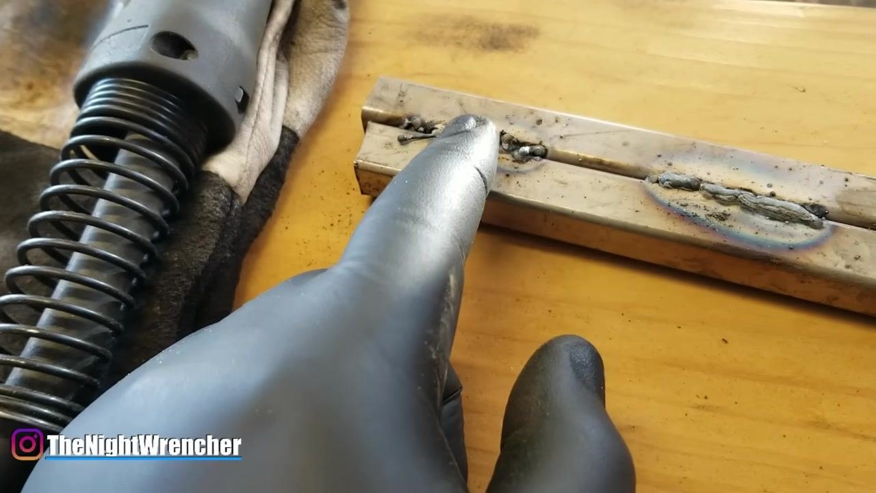
Verify your stick-out distance
Keep the welding wire stick-out at approximately two to three units (millimeters or the length recommended for your process). Use a pinching gesture near the tip to gauge and confirm this distance during a pause in welding.
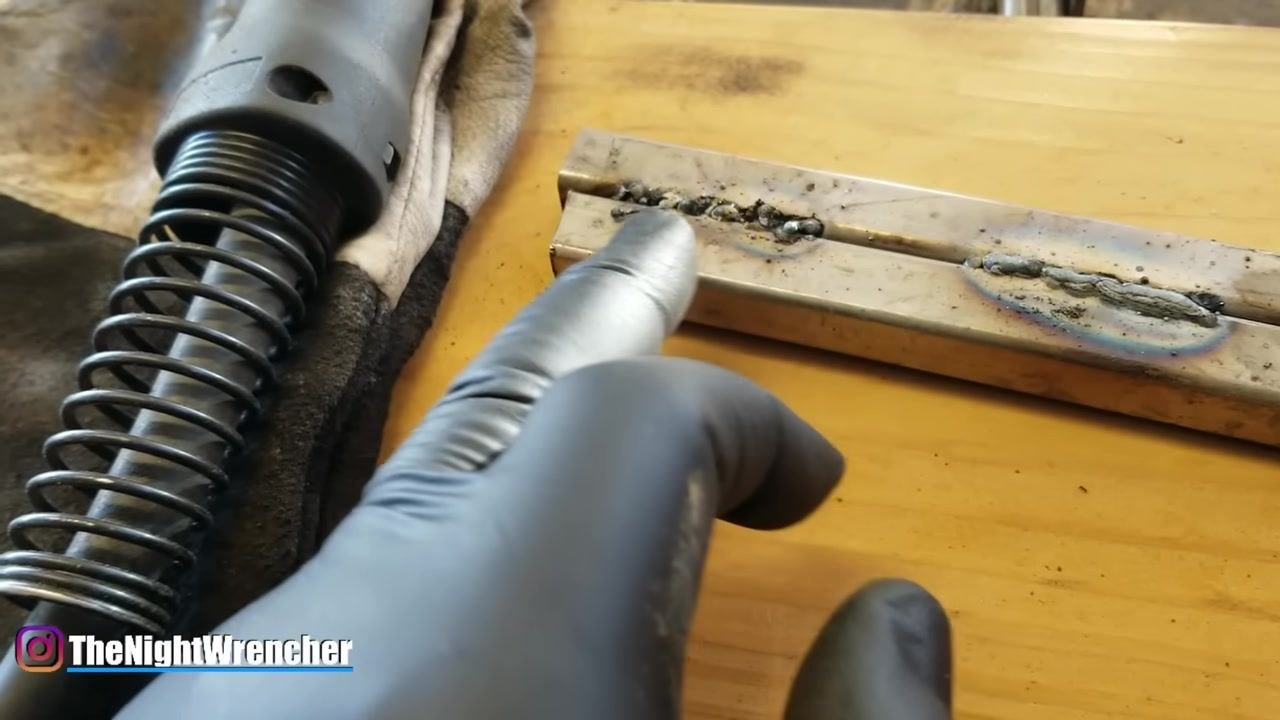
Control your welding speed
Move at a steady pace along the joint to ensure proper fusion and bead formation. Moving too quickly can result in weak, inconsistent welds.
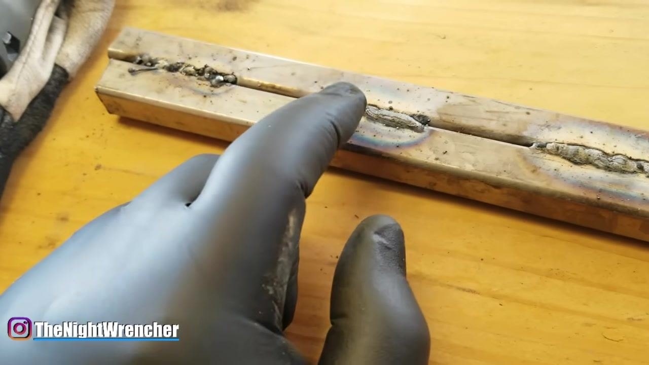
Adjust the gun angle
Beyond distance and stick-out, check that your gun is not angled too far forward or backward, as an incorrect gun angle can negatively affect your welds.
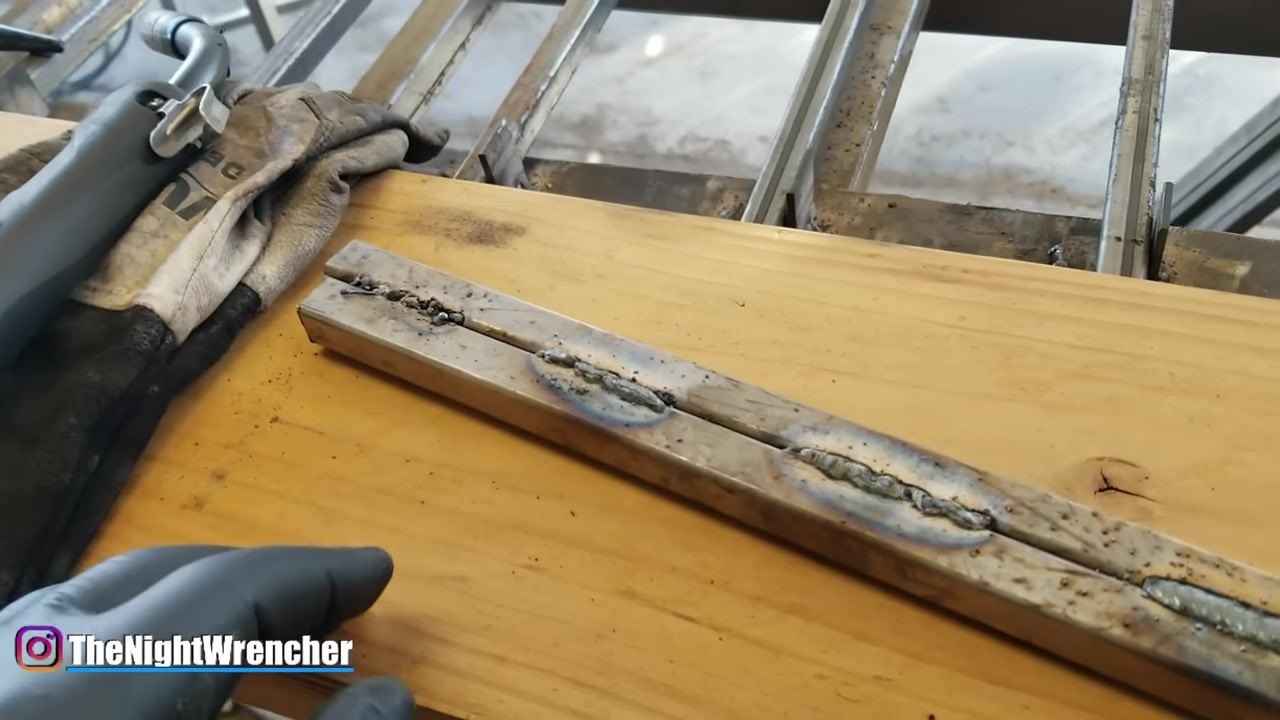
Confirm proper gun orientation
Avoid pointing your welding gun excessively forward or backward relative to the weld seam. The correct angle helps you control the weld puddle and prevents defects.
Understand how slag forms
As you weld, flux inside the wire melts and rises to the surface as the weld cools, forming a protective layer called slag. This layer must be removed for a clean finish.
Identify slag on the weld surface
Look for a dull, crusty layer on top of the weld bead—this is slag, and it does not look aesthetically pleasing. Once the weld cools, plan to remove it with a chipping hammer or wire brush to reveal the underlying weld.
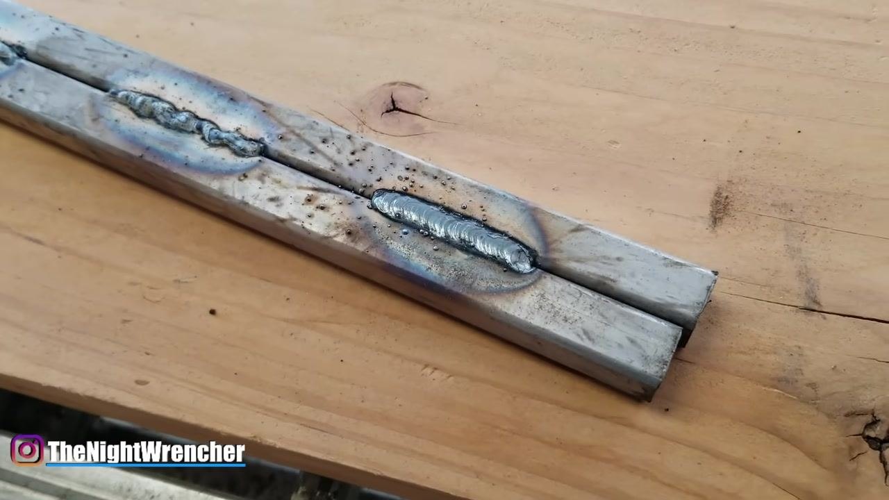
Prepare your tools for slag removal
Place your chipping hammer or wire brush within reach before you begin the cleaning process so you can move directly from welding to cleanup.
Examine ripples for puddle control
After removing slag, inspect the weld bead for visible ripples, which indicate the direction and control of your welding puddle. Proper puddle control results in uniform, consistent ripples along the weld bead.
Check for porosity and irregular bead shape
If your weld bead "eats into itself" or appears porous, this indicates issues such as incorrect gun angle, speed, or insufficient shielding. Porosity and irregular bead shape are signs of poor technique that require correction.
Maintain technique to prevent porosity
Ensure your gun angle, speed, and stick-out are correct to prevent air pockets and weak welds. Consistent technique across all three factors reduces the risk of porosity.
Control the direction of your weld puddle
Push the puddle in the correct direction to ensure a smooth, even weld bead. Deliberate puddle direction control is part of achieving a consistent finish.
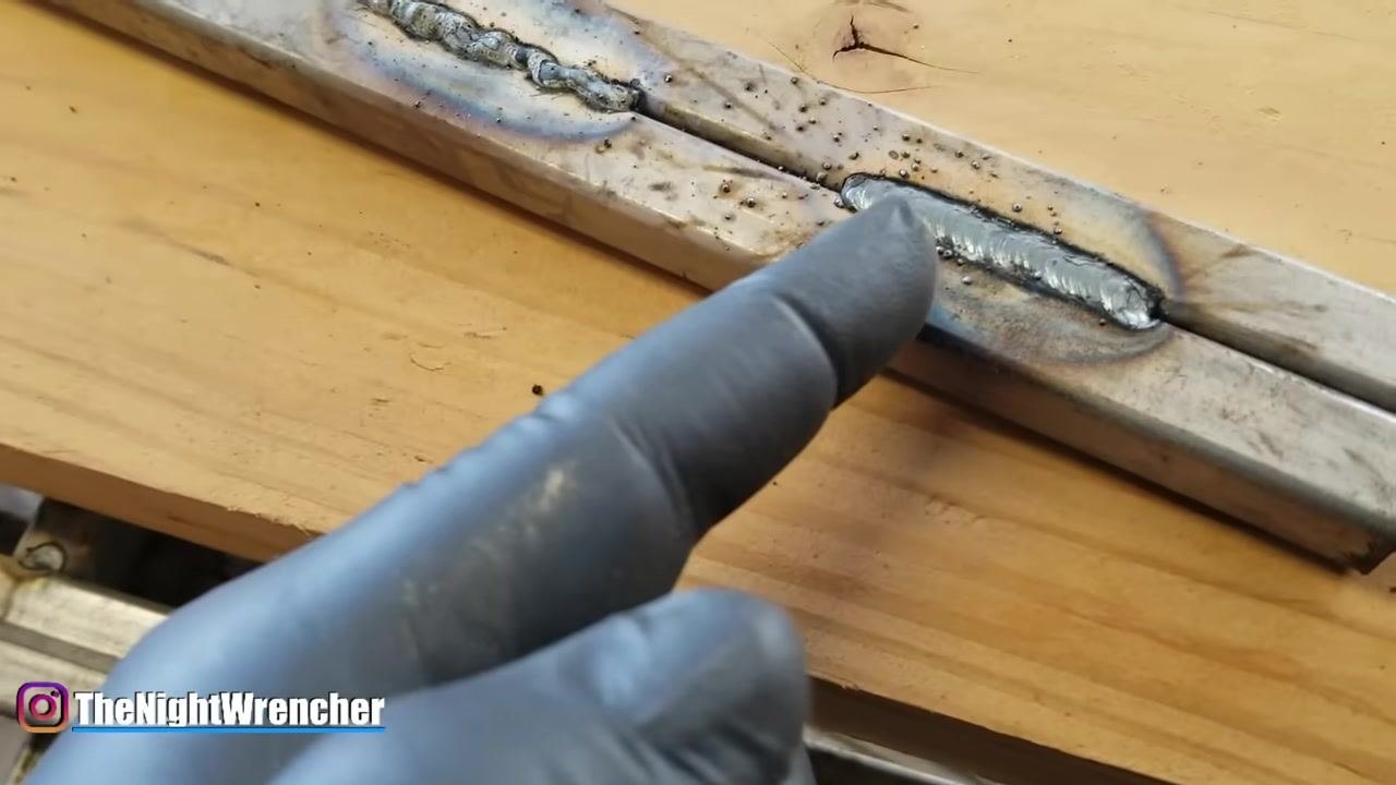
Drag the weld along the seam
Use a steady, controlled motion to drag the weld puddle along the joint for the best results. This dragging motion supports proper slag formation and bead consistency.
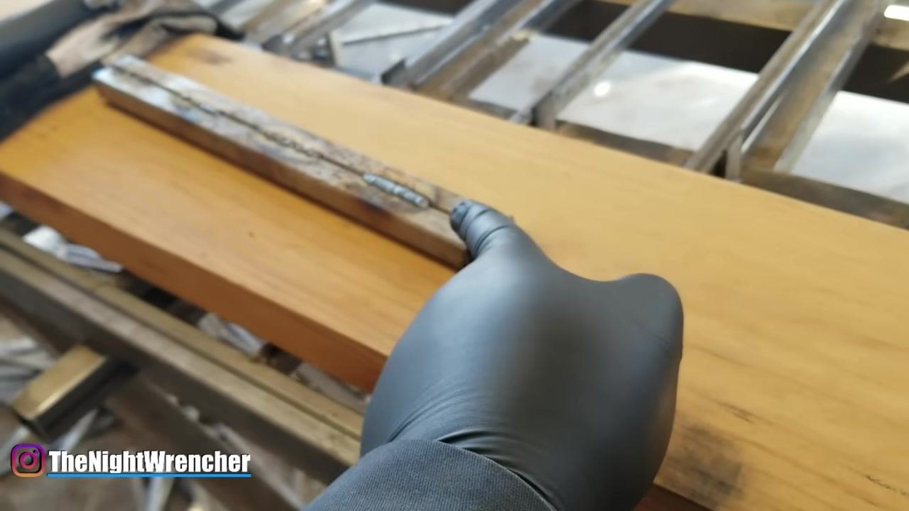
Apply the "if it has slag, you drag" principle
When flux core welding, always drag the welding gun away from the weld puddle to ensure proper slag formation and removal. Welds produced this way will show visible slag and heat discoloration as expected results of the dragging technique.
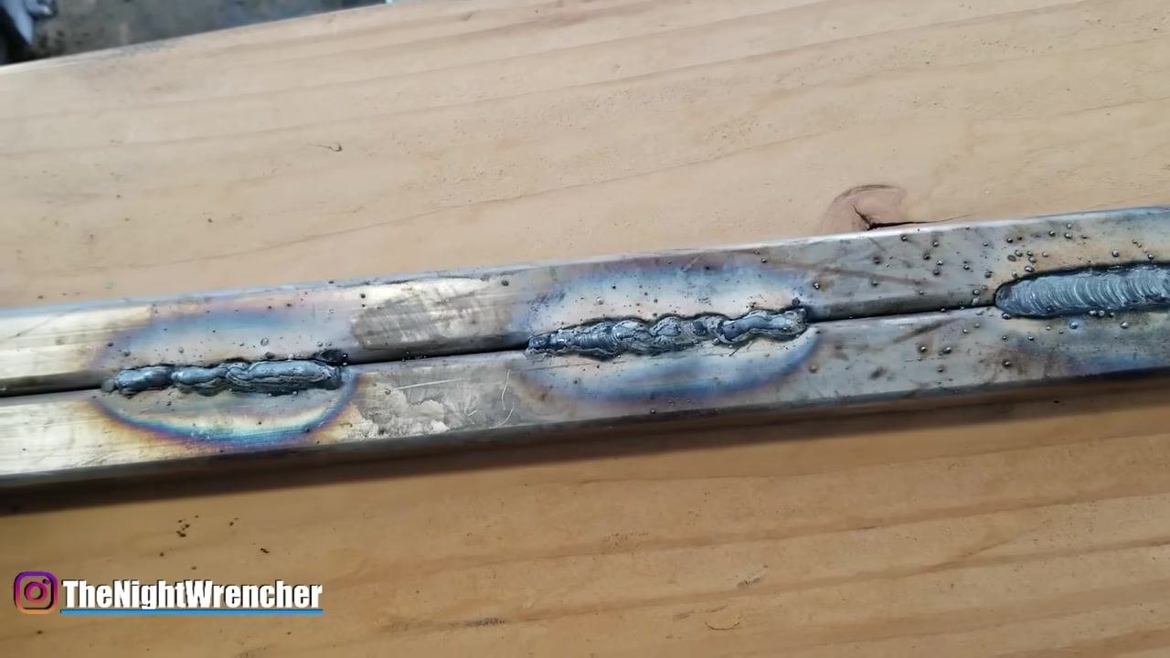
Check for shiny material indicating incomplete slag removal
Inspect your welds for areas with shiny material, which may indicate incomplete slag removal or inconsistent weld quality. Hold your chipping hammer ready to address any remaining slag.
Inspect surface quality after slag removal
After using a chipping hammer or wire brush, closely inspect the weld bead for uniformity and smoothness. Some beads will look smoother and more consistent than others, which helps you identify where technique needs improvement.
Clean the weld area thoroughly
Blow off loose slag and use a wire brush or chipping hammer to clean the weld area thoroughly, ensuring no debris remains on or around the bead.
Apply anti-spatter spray
Apply anti-spatter spray to your workpiece before welding to minimize spatter sticking to the material, which makes post-weld cleanup easier and results in a neater finish.
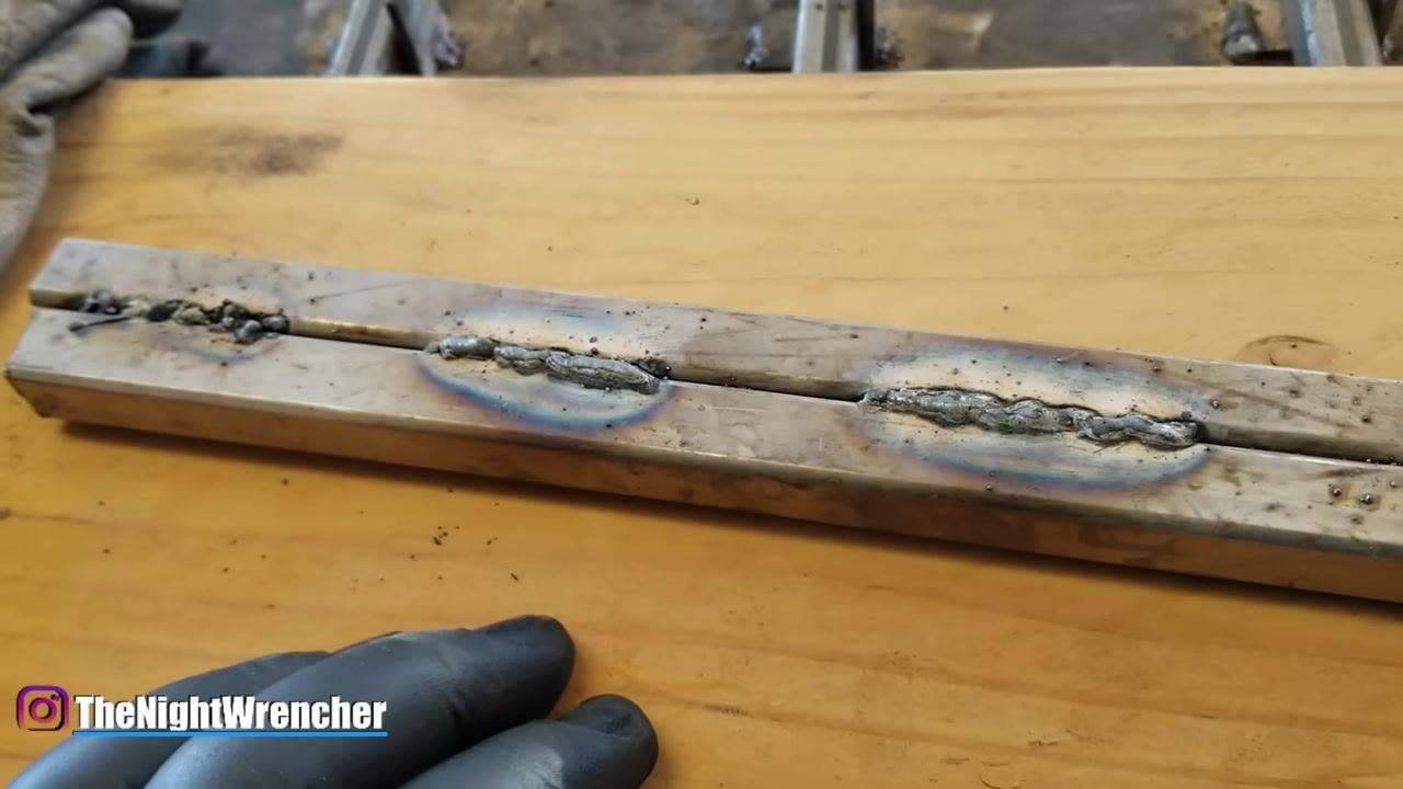
Focus on hand control for consistent results
Practice steady hand movements to transform inconsistent, porous welds into smooth, uniform beads. Compare poor and improved welds side by side to track your progress.
Verify improvement through self-assessment
Use visual inspection to compare your welds and identify areas for improvement in technique and consistency. Look for a smooth, consistent weld bead as your benchmark, contrasted against any remaining rougher beads on the same workpiece.
Verification and summary
To confirm you are flux core welding correctly, review the following checklist against your finished welds:
- Weld bead shows fusion with the base metal, not filler sitting on top
- Gun distance keeps a stick-out of about 1/2" to 3/4", never touching the tip to the workpiece
- Travel speed is steady and moderate, avoiding both excessive speed and excessive dwell
- Gun angle is neither too far forward nor too far backward
- Slag has been fully removed with a chipping hammer or wire brush, revealing a consistent bead underneath
- Ripples along the bead are uniform, indicating good puddle control
- No visible porosity, cracks, gaps, or unmelted wire protruding from the bead
- Anti-spatter spray was applied beforehand to ease cleanup
- Protective gear, including gloves and heat-shielding clothing, was worn throughout
Consistent flux core welding results come from controlling hand movement, gun distance, stick-out, travel speed, and gun angle together, then confirming quality through slag removal and visual inspection of the finished bead.
Generation details: cost, quality tiers
Docsie billed 5,000 credits ($3.50) to analyze this 10-minute video at standard quality. The rewrite, template fill and Word/PDF exports were included. The same video at each quality tier:
| Quality | Frames sampled | Credits | Approx. cost |
|---|---|---|---|
| Draft | every 16-30 s | 2,500 | $1.75 |
| Standard (this guide) | every 8-15 s | 5,000 | $3.50 |
| Detailed | every 4-7 s | 10,000 | $7.00 |
| Ultra | every 1-3 s | 20,000 | $14.00 |
Credits priced at $0.70 per 1,000; plans include a monthly allowance. Enterprise customers on on-premise or bring-your-own-model deployments run this on their own inference and pay no per-video credits.
Generated by Docsie Video-to-Docs on 2026-09-14 from a 9-minute video. Screenshots are frames from the source video and belong to their creator, NightWrencher, whose original is embedded above. If you own this video and want the guide removed or credited differently, contact us and we will act within one business day.