
How to Fix Short Shot in Injection Molding
Short shot, also known as a "short mold," is one of the most common defects encountered in plastic injection molding. It occurs when the cavity in the mold is not fully filled with material, resulting in incomplete parts that must be rejected. This document explains how to fix short shot in injection molding by walking through a systematic diagnostic process — from recognizing the defect, to checking machine parameters, to confirming that the issue has been resolved on the shop floor.
Video: Fix It Live || Episode 01 || Short Shot (mold) problem in Plastic Injection Molding by Plastic Tech India (2026). All credit for the demonstration goes to the creator; watch the original on YouTube. The written guide below was generated from this video by Docsie. Creator? Request a change or removal.
Short shot, also known as a "short mold," is one of the most common defects encountered in plastic injection molding. It occurs when the cavity in the mold is not fully filled with material, resulting in incomplete parts that must be rejected. This document explains how to fix short shot in injection molding by walking through a systematic diagnostic process — from recognizing the defect, to checking machine parameters, to confirming that the issue has been resolved on the shop floor.
Purpose
This procedure guides operators and engineers through identifying the root cause of a short shot defect and applying the correct corrective adjustments on the injection molding machine, rather than making random parameter changes.
Scope
This procedure applies to injection molding operations where molded parts are being rejected due to incomplete cavity filling. The steps below were demonstrated on a production machine running ABS material with a Milacron Endura control panel, but the diagnostic sequence applies to short shot troubleshooting generally.
Required equipment and materials
- Injection molding machine with an accessible control panel (e.g., Milacron Endura)
- Sample molded parts, including rejected (short) parts and good parts, for comparison
- Reference or inspection sheets for quality documentation
- A pointer tool for indicating defect locations on the part
Safety note: Work within the posted workshop safety signage and standard facility procedures whenever you are near the mold area, control panel, or moving machine components.
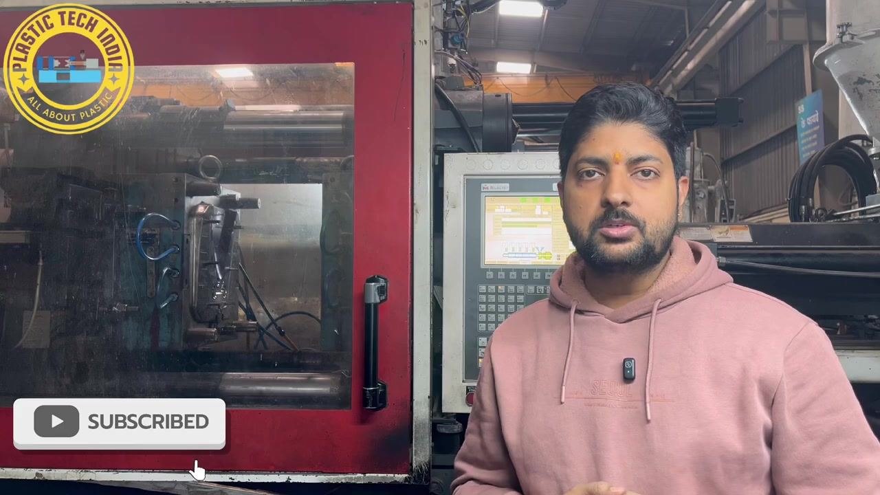
Recognize a short mold defect
A short mold is a molded part that is incomplete because the material did not reach all areas of the cavity. Parts with this defect must be rejected due to incomplete filling.
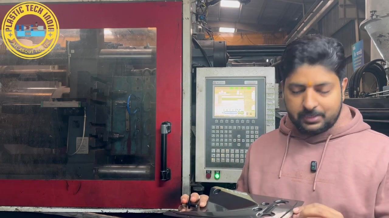
Inspect a rejected sample part
Hold up a rejected part and visually confirm the incomplete filling caused by the short mold defect. This confirms that the defect is present before you begin adjustments.
Apply the standard first-response adjustments
When a short mold occurs, engineers, supervisors, or operators typically respond by:
- Increasing the speed of injection
- Increasing the injection pressure
- Increasing the clamp tonnage if it is found to be low
These adjustments are intended to help ensure the last filling area of the mold is properly filled.
Note: Always reject parts that are not fully filled and document the defect for quality control before proceeding further.
Avoid random adjustments without diagnosis
Caution: Do not randomly increase injection speed, pressure, or shot size without first understanding the underlying cause of the short mold defect. Always investigate the root cause before making parameter changes.
Check for the actual cause during production
When a short mold occurs during production, systematically check the reasons behind it rather than simply increasing machine parameters.
Identify the key diagnostic areas
When troubleshooting systematically, focus on the following key areas:
- Cushion variation: After injection, check the raw material left in the barrel (the screw cushion) for consistency.
- Transfer position (V switch over): Verify the velocity-to-pressure switch over point, which is the transition from injection speed to holding pressure. Any discrepancy here can cause short molding.
- Melt temperature: Check the melt temperature across all barrel zones. If there are 4 or 5 heating zones, confirm none of the heaters are weak or malfunctioning, as this can lead to incomplete filling.
- Cushion variation causes: If cushion variation is observed, investigate possible leakage in the ring plunger or poor contact between the nozzle and the mold.
Inspect items in the correct sequence
Inspect the following in sequence:
- Cushion consistency after injection
- Correctness of the velocity-to-pressure switch over position
- Uniformity and adequacy of melt temperature in all barrel zones
- Possible mechanical issues such as ring plunger leakage or nozzle-mold contact problems
Verify the velocity-to-pressure switch over
Confirm that the switch over from injection velocity to holding pressure is set correctly. Incorrect settings at this transition point can result in incomplete filling.
Check barrel heater zones
If the barrel has multiple heating zones (for example, 4 or 5), verify that all heaters are functioning properly. A weak or faulty heater can under-melt the material, leading to short molding.
Investigate cushion variation causes
If cushion variation is detected, determine whether it is due to:
- Leakage in the ring plunger
- Poor contact between the nozzle and the mold
Review the full set of troubleshooting points
The key points to check are:
- Cushion consistency
- Switch over position (velocity to pressure)
- Melt temperature in all zones
- Mechanical issues (ring plunger, nozzle-mold contact)
Confirm the order of checks
Start by checking the cushion, then move on to check the switch over position, following the diagnostic sequence in order.
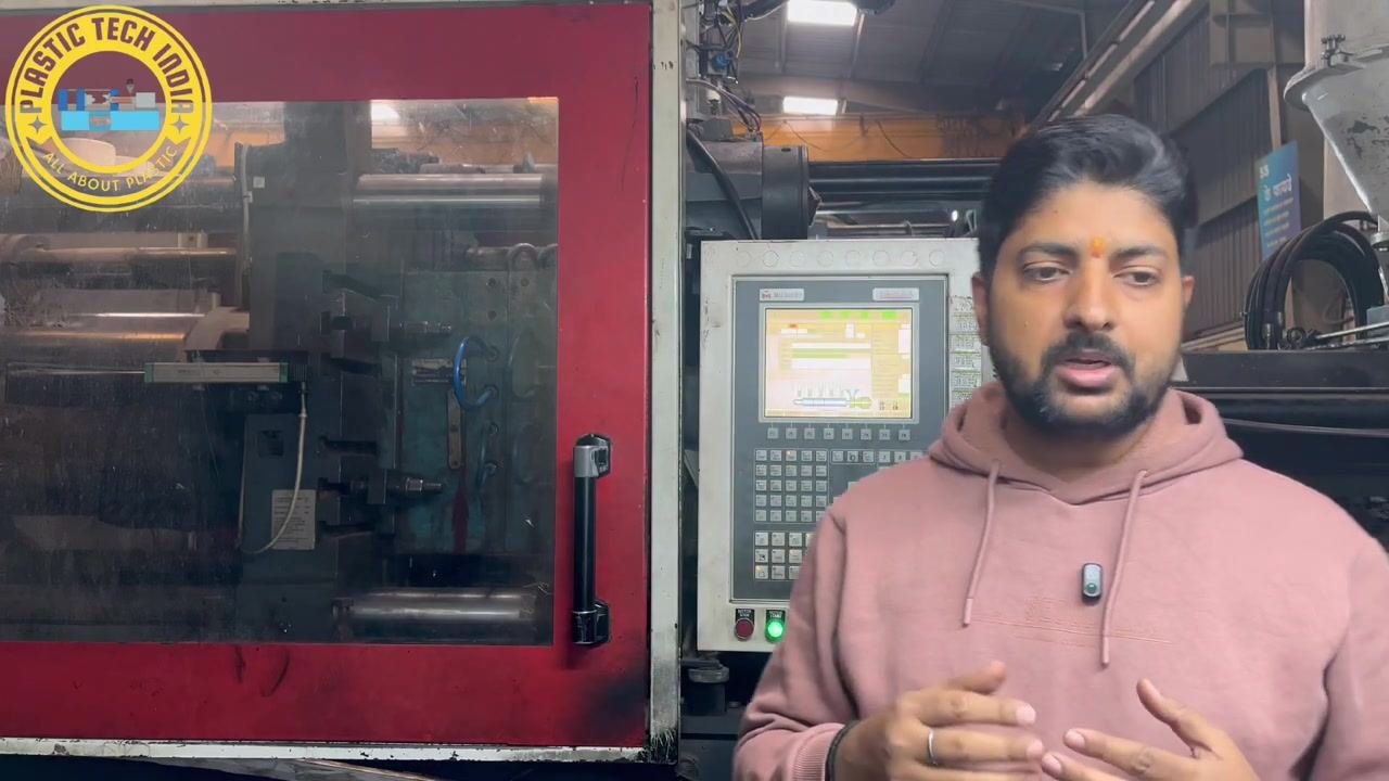
Check for material leakage at the nozzle
Inspect the nozzle area for any signs of leakage. Even minor leakage at the nozzle can cause material loss, resulting in incomplete filling. Material intended for the cavity may escape at the nozzle, leading to defects.
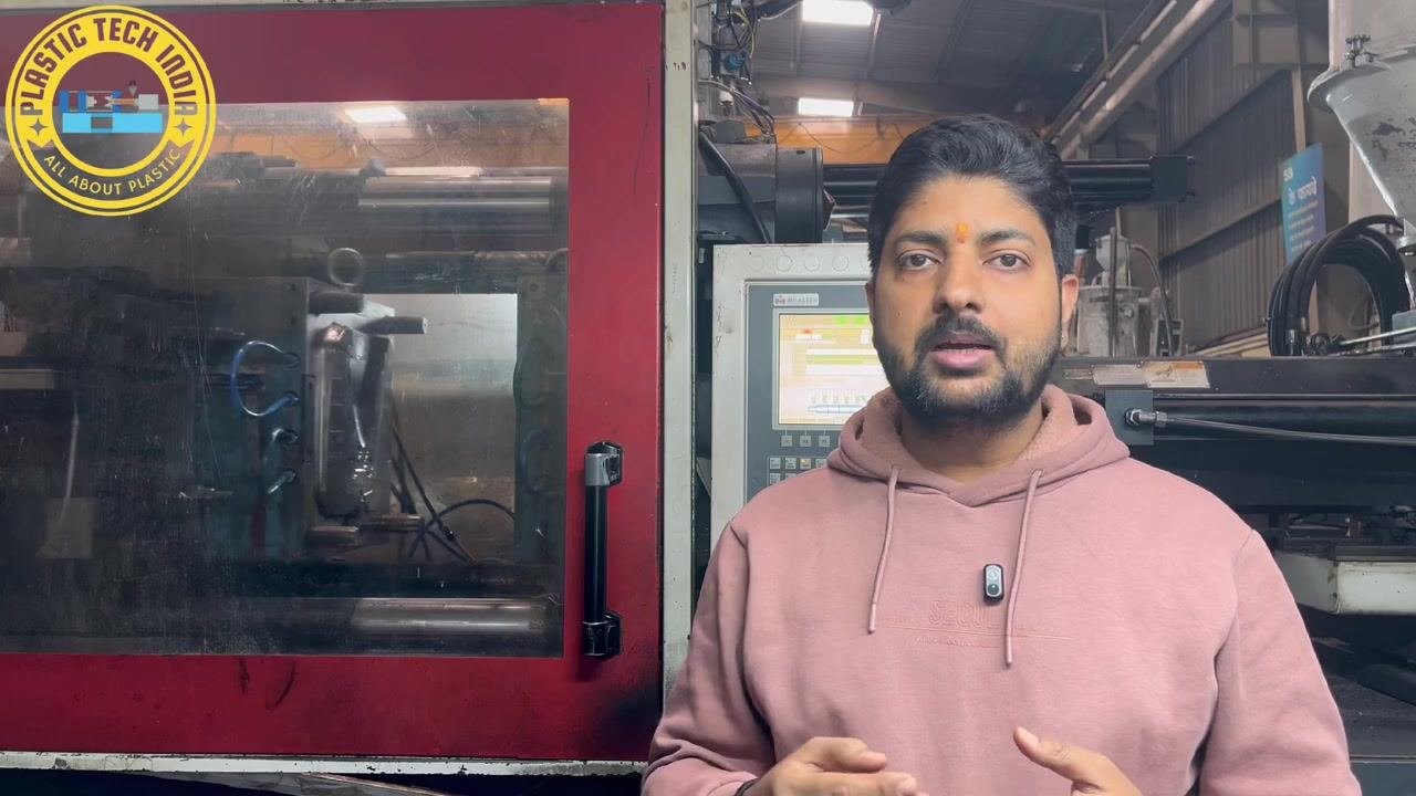
Start the machine for live troubleshooting
Start the injection molding machine to observe real-time production conditions, and prepare to systematically check the five key diagnostic points identified above.
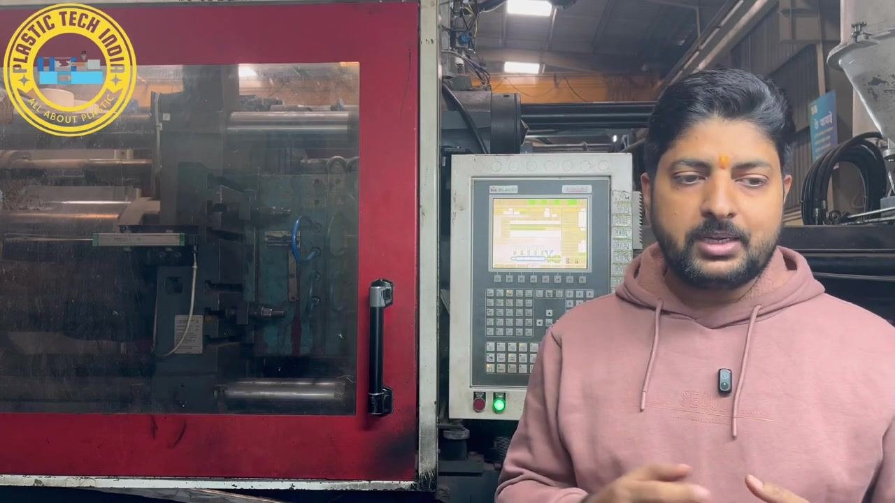
Observe the mold during operation
Watch the mold as it runs to identify any immediate issues, such as short filling, and note any visible defects in the produced part.
Inspect the produced part for short fill
Examine the molded part for evidence of short filling or incomplete areas. Hold the part up for close inspection, focusing on areas where material may not have filled properly.
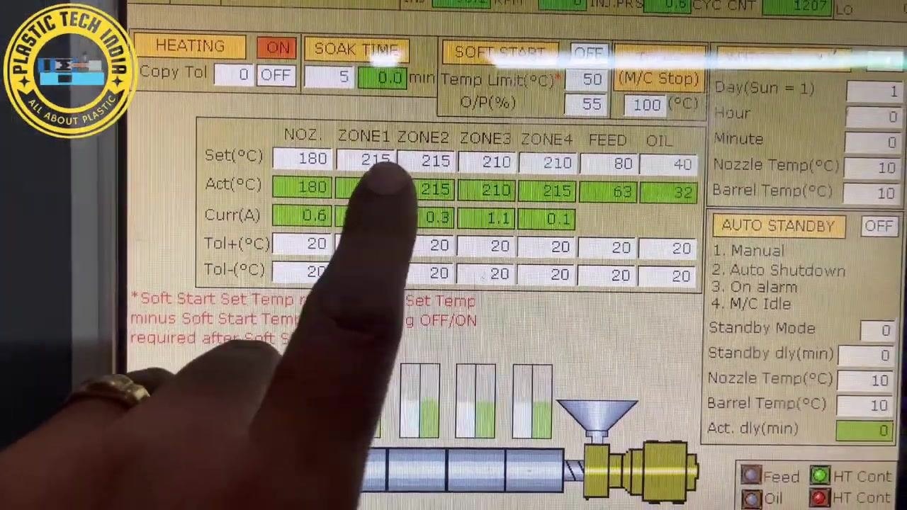
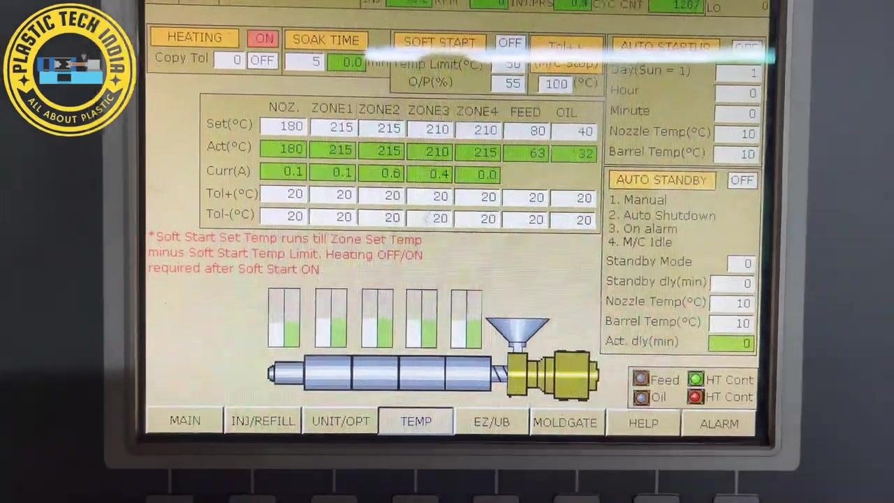
Check barrel temperature settings
Go to the temperature control zone on the machine's control panel and confirm the material in use (ABS in this case). Review the temperature settings for each barrel zone:
- Nozzle: 180°C
- Zone 1: 215°C
- Zone 2: 215°C
- Zone 3: 210°C
- Zone 4: 215°C
- Feed: 63°C
- Oil: 32°C
Ensure the actual temperatures match the set values, indicating no variation.
Verify uniformity of barrel temperatures
Confirm that the front zone (Zone 1) is set to 215°C and the last zone (feed zone) is set to 210°C. Check that all zones fall within the specified tolerance with no significant variation.
Confirm whether temperature adjustment is needed
If all temperature zones are stable and within tolerance, no changes are needed in the temperature settings. Move on to the next diagnostic point if temperature is not the cause.
Observe cushion speed and position data
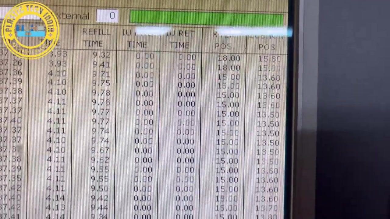
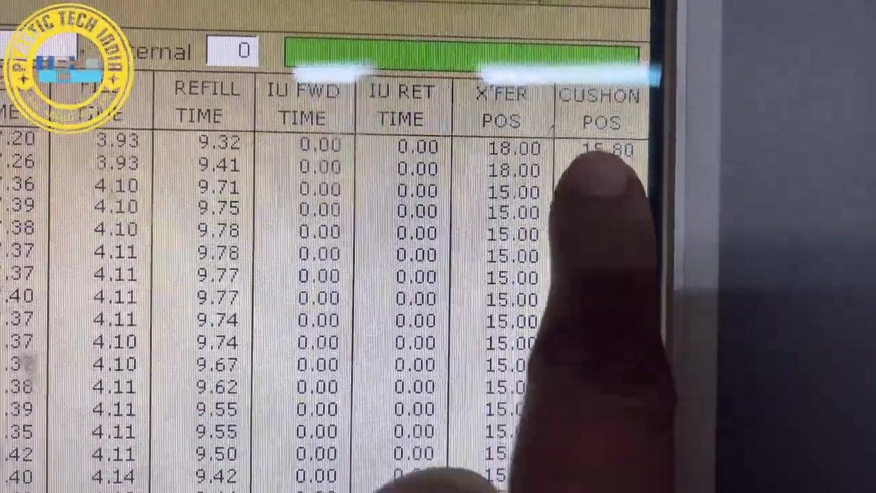
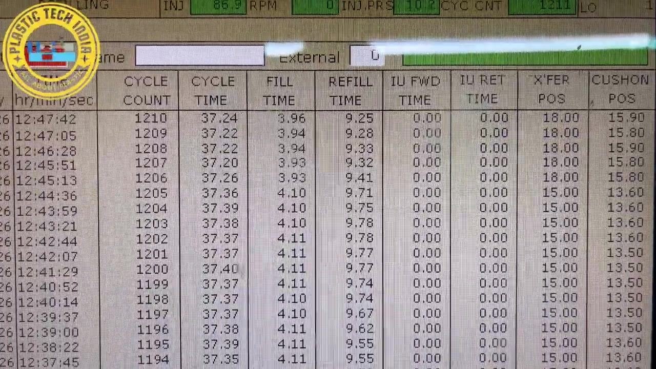
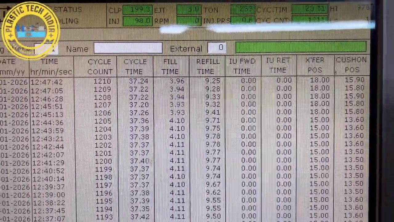
Locate the machine interface table with columns such as REFILL TIME, IU FWD TIME, IU RET TIME, XFER POS, and CUSHION POS. In this example, the CUSHION POS column shows a value of 15.80 mm.
Review the complete injection and refill settings
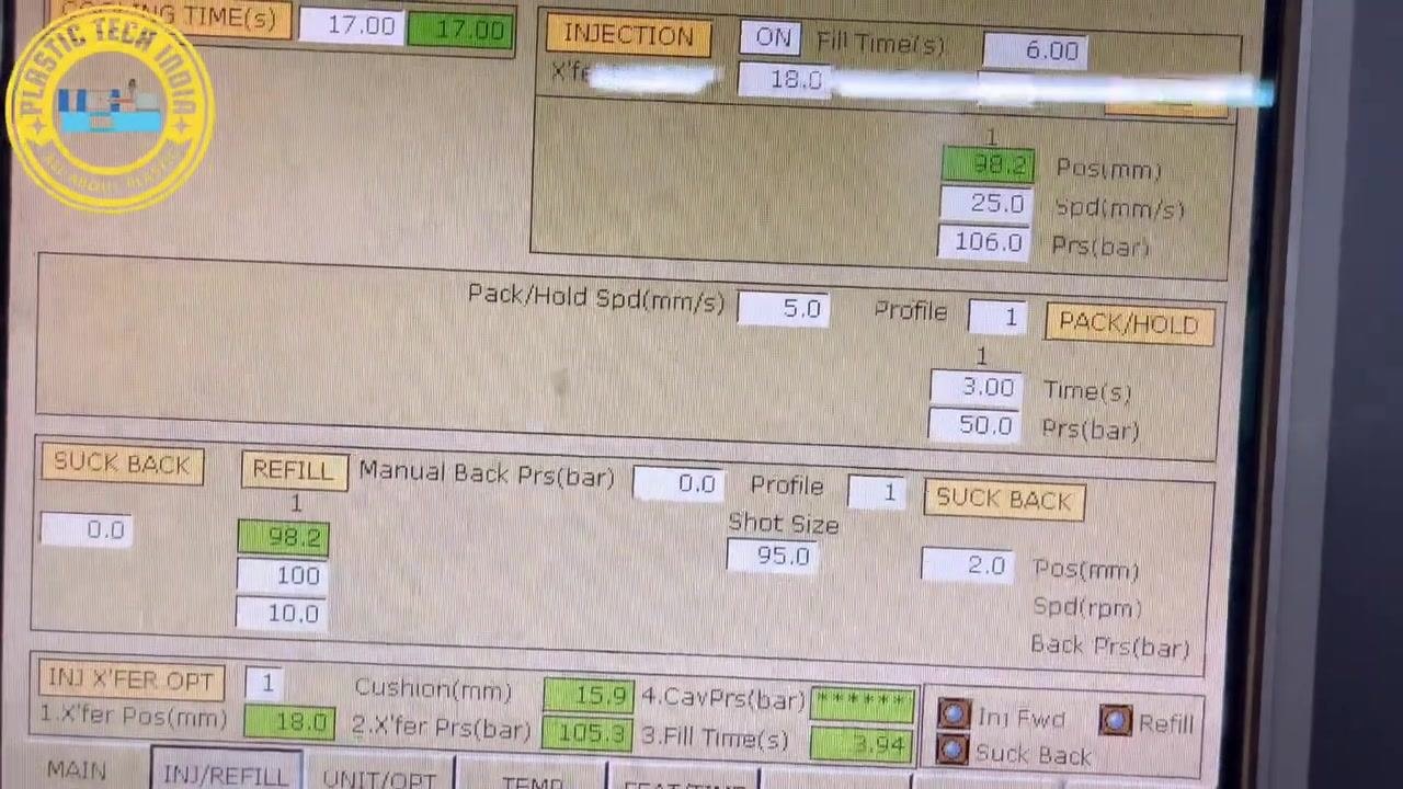
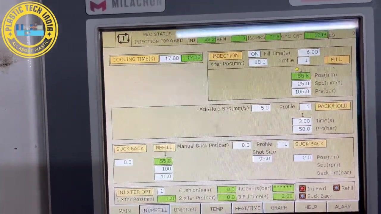
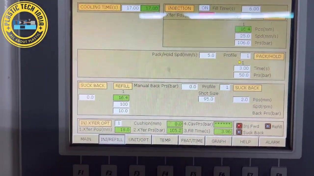
Review the key parameters displayed on the control panel:
- COOLING TIME(s): 17.00
- INJECTION: ON, Fill Time(s): 6.00, Xfer Pos(mm): 18.0, Profile: 1
- Position (mm): 38.2, Speed (mm/s): 25.0, Pressure (bar): 106.0
- Pack/Hold: Speed (mm/s): 5.0, Profile: 1, Time(s): 3.00, Pressure (bar): 50.0
- SUCK BACK: 0.0, REFILL: 98.2, 100, 10.0
- Manual Back Pressure (bar): 0.0, Profile: 1, Shot Size: 95.0
- INJ X'FER OPT: Xfer Pos(mm): 18.0, Cushion(mm): 15.9, Xfer Prs(bar): 105.3, Fill Time(s): 3.94
Identify the refill position
Locate the Shot Size field, which is set to 95.0 mm. This value indicates the refill position, which is the amount of material being refilled for each cycle.
Check the pack/hold pressure settings
Locate the PACK/HOLD section, specifically the time (3.00 s) and pressure (50.0 bar) fields. These values control how long, and at what pressure, the material is held after injection.
Confirm the transfer position value
Check the upper section of the control panel for the Xfer Pos(mm) field. In this case it reads 15.0, confirming the transfer position for the injection process.
Confirm the transition to holding phase
Locate the PACK/HOLD section again to confirm that, after the transfer position of 15 mm, the material transitions into the holding phase.
Review the overall process and part status
Step back to view the entire control panel and part of the machine, confirming that all the parameters reviewed so far reflect the current setup and process status.
Navigate to the cushion monitoring page
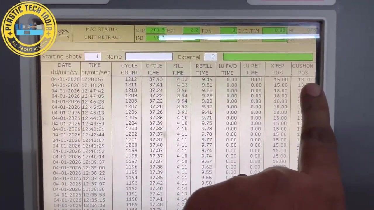
Locate the CUSHION POS column in the process cycle log. In this check, the current value is 15.90 mm, indicating no change has occurred since the last check.
Confirm initial process changes produced an acceptable part
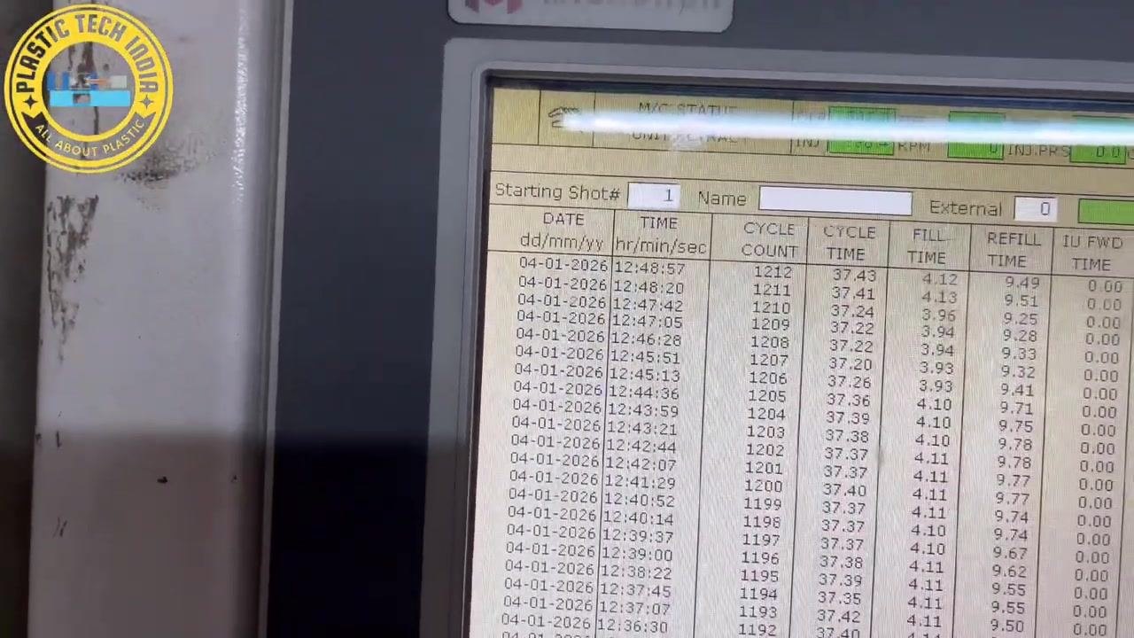
Review the process log, including cycle count, fill time, refill time, transfer position, and cushion position, to confirm that the first set of changes has produced an "OK" part.
Verify the process log after changes
Confirm the consistency of the process parameters after the initial adjustments by reviewing the CYCLE COUNT, FILL TIME, REFILL TIME, X'FER POS, and CUSHION POS columns.
Observe part ejection
Watch the mold open and the part being ejected. Blue coolant lines and the mold cavity are visible, with the newly formed plastic part inside the mold.
Inspect the produced part for quality
Move the molded plastic part to a workbench for inspection. Check the part, which is black with multiple circular and rectangular features, against reference material for inspection.
Identify the area of previous short molding
Use a pointer to indicate the specific area on the molded part where short molding (incomplete filling) was previously observed. Compare the part to another sample to review the material flow path and the critical area for quality.
Re-check the cushion position after the process change
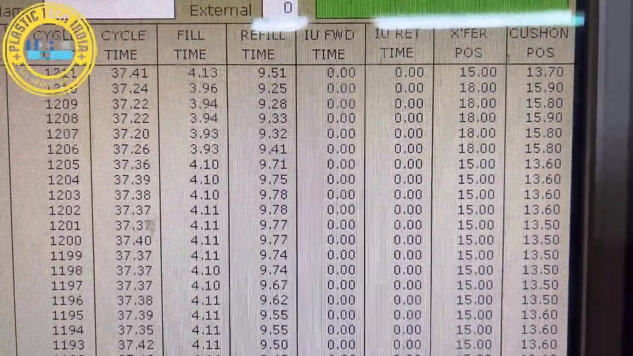
Return to the machine interface and check the CUSHION POS column. It now shows a value of 13.70 mm for the latest cycle, indicating a change from the previous value.
Prepare for further process adjustments if needed
Keep the process log open and ready for additional changes if further optimization is required.
Inspect the injection unit closely
Zoom in on the injection unit of the molding machine to inspect the injection barrel, heater bands, wiring, and any residue from previous runs.
Examine the nozzle area in detail
Continue inspecting the injection area, focusing on the nozzle and surrounding components, including wiring, residue, and the mechanical structure of the injection system.
Confirm the process adjustment has resolved the issue
Check the CUSHION POS column again. It now consistently shows a value of 13.70 mm for the latest cycles, confirming that the process change has successfully addressed the short molding issue.
Inspect final molded parts for quality assurance
Place two black molded plastic parts side by side on the workbench for comparison. Confirm that both parts have multiple circular and rectangular features with smooth, defect-free surfaces. Reference inspection sheets should be available for ongoing quality checks.
Compare multiple parts to confirm process consistency
Verify that both parts are identical in appearance and free from short molding or other defects.
Prepare for the next production cycle
Review the wider production area, including stacks of black molded parts in bins and trays, to confirm readiness to repeat the optimized process for subsequent cycles.
Verify cushion position consistency across parts
Return to the machine interface and check the CUSHION POS column for the last three entries. All three should read 13.70 mm, confirming stable and repeatable process conditions.
Review the final process parameters
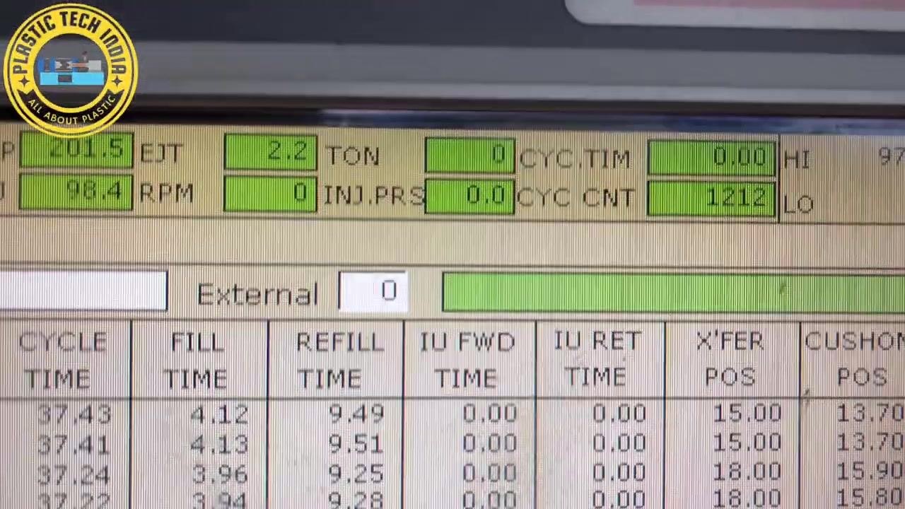
Check the PACK/HOLD section, confirming settings of 3.00 seconds and 50.0 bar. Also review the refill pressure (98.4 bar) and shot size (95.0). Confirm that the cavity was filled with the maximum material before transitioning to holding after 15 mm.
Conclude the procedure
Review the full machine interface, including all relevant process parameters, to confirm the completed and validated process.
Verification and summary
Confirm the following before closing out the corrective action:
- The short mold defect was recognized by inspecting for incomplete filling in the molded part.
- The root cause was investigated systematically rather than through random parameter changes, covering cushion consistency, switch over position, melt temperature across all barrel zones, and mechanical issues such as ring plunger leakage or nozzle-mold contact.
- Barrel temperature zones were checked and confirmed to be within tolerance.
- The cushion position was monitored before and after adjustment, moving from 15.80–15.90 mm to a stable 13.70 mm across the last three parts.
- The transfer position was set to 15 mm, with the process transitioning to the pack/hold phase (3.00 s, 50.0 bar) after this point.
- The produced parts were inspected and compared, confirming smooth, defect-free surfaces and no recurrence of short molding.
- Parts that are not fully filled must always be rejected and the defect documented for quality control.
What's next
Once the cushion position and part quality remain stable across multiple cycles, continue production using the optimized settings. Repeat this diagnostic sequence — cushion check, switch over position, melt temperature, and mechanical inspection — any time a short mold defect reappears, rather than defaulting to random parameter increases.
Generation details: cost, quality tiers
Docsie billed 5,000 credits ($3.50) to analyze this 10-minute video at standard quality. The rewrite, template fill and Word/PDF exports were included. The same video at each quality tier:
| Quality | Frames sampled | Credits | Approx. cost |
|---|---|---|---|
| Draft | every 16-30 s | 2,500 | $1.75 |
| Standard (this guide) | every 8-15 s | 5,000 | $3.50 |
| Detailed | every 4-7 s | 10,000 | $7.00 |
| Ultra | every 1-3 s | 20,000 | $14.00 |
Credits priced at $0.70 per 1,000; plans include a monthly allowance. Enterprise customers on on-premise or bring-your-own-model deployments run this on their own inference and pay no per-video credits.
Generated by Docsie Video-to-Docs on 2026-09-14 from a 9-minute video. Screenshots are frames from the source video and belong to their creator, Plastic Tech India, whose original is embedded above. If you own this video and want the guide removed or credited differently, contact us and we will act within one business day.