
How to Cut Threads on a Lathe
This procedure explains how to cut threads on a lathe, from exposing and configuring the internal gear train to making successive threading passes and verifying the finished thread with a gauge. Follow each step in order, since correct gear configuration and tool alignment are required before any threading pass is made.
Video: how to CUT THREADS on a harbor freight mini metal lathe by Live Free (2020). All credit for the demonstration goes to the creator; watch the original on YouTube. The written guide below was generated from this video by Docsie. Creator? Request a change or removal.
This procedure explains how to cut threads on a lathe, from exposing and configuring the internal gear train to making successive threading passes and verifying the finished thread with a gauge. Follow each step in order, since correct gear configuration and tool alignment are required before any threading pass is made.
Purpose
This document provides a step-by-step method for setting up a lathe's gear train, aligning the threading tool, using the thread dial and half-nut, and cutting threads to the correct depth and pitch on a metal lathe.
Scope
This procedure applies to operators setting up a lathe for thread cutting, including gear train configuration, compound rest alignment, threading tool pickup, and final inspection of cut threads. It covers both straight-in feeding (suitable for softer materials such as wood) and angled compound rest feeding (used for precise metal threading).
Requirements
- A lathe with an accessible gear train, threading chart, and thread dial
- A set of replacement change gears with varying teeth counts
- A threading tool with the correct point angle for the thread profile
- A fishtail gauge, or a large standard bolt as an alternative alignment tool
- A thread pitch gauge for verification
- An Allen key or wrench for securing bolts
- Eye protection
Safety note: Always wear eye protection and keep hands clear of moving parts during operation. Never change gears while the lathe is running.
Expose and understand the lathe gear train
- Remove the back cover of the lathe to expose the internal gears. This provides access to the gear train and threading chart, both located on the left side of the lathe.
-
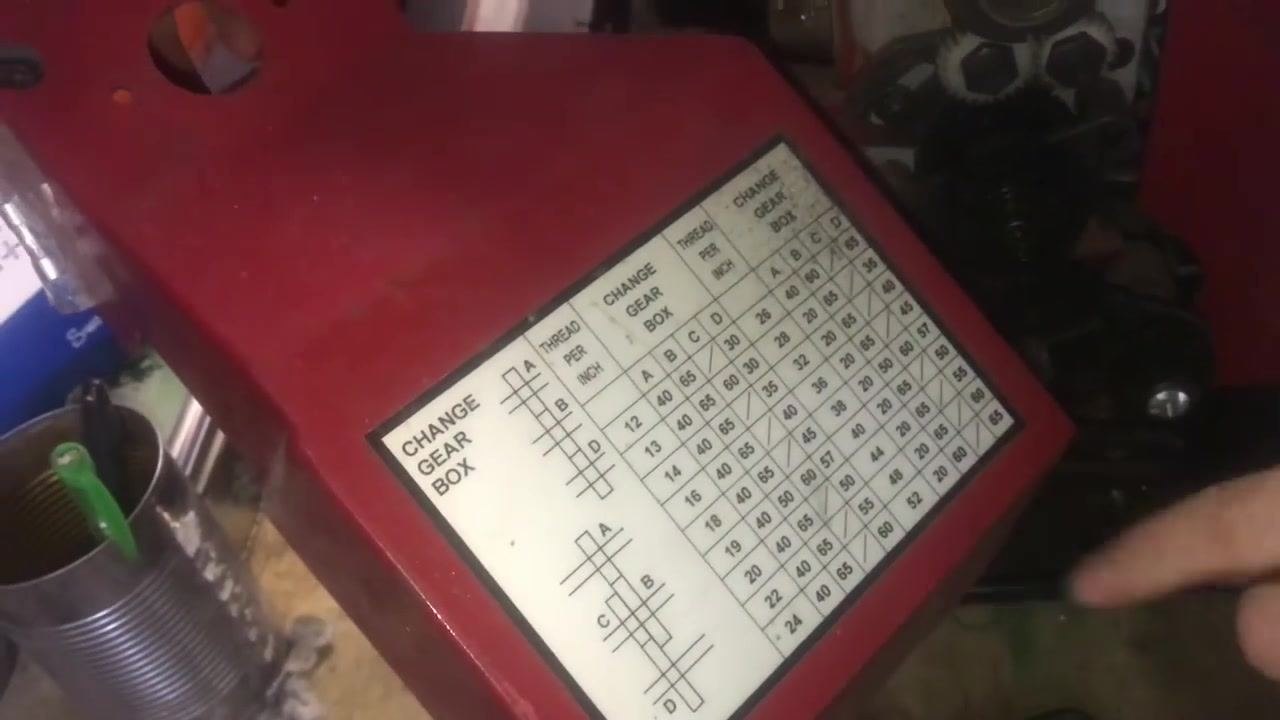
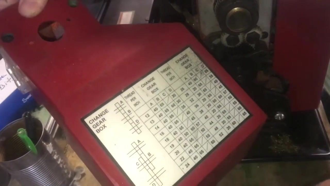
Locate the threading chart on the inside of the cover. The chart lists available threads per inch (TPI) ranging from 12 to 52 in varying increments, along with the required gear combinations for each TPI.
-
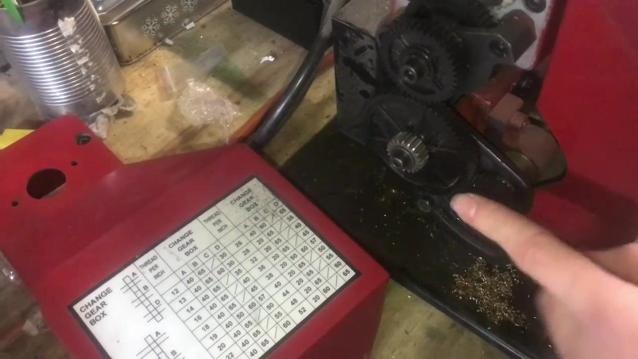
Identify the replacement gears stored nearby. These gears, which have different numbers of teeth, are used to change the ratio between the spindle and the lead screw.
- Review the gear configuration for the current threading setup. In this example, the lathe is set up for 12 TPI, the coarsest setting available. This configuration uses gears A, B, and D, with gear C not engaged (indicated by a slash in the C column on the chart). The gears in use are: A = 40 teeth, B = 65 teeth, D = 30 teeth.
- Understand the gear arrangement. Gear A is the topmost gear, gear B is the middle gear, and gear D is the bottom gear, connected to the lead screw. Gear C is not used in this configuration. If a number appears in the C column for a different TPI, gear C must be installed and engaged.
- Note: If gear C is required for a different threading configuration, install the correct spacer and gear as indicated by the chart, which provides visual diagrams for gear arrangements with and without gear C.

Adjust the gear train and set up for thread cutting
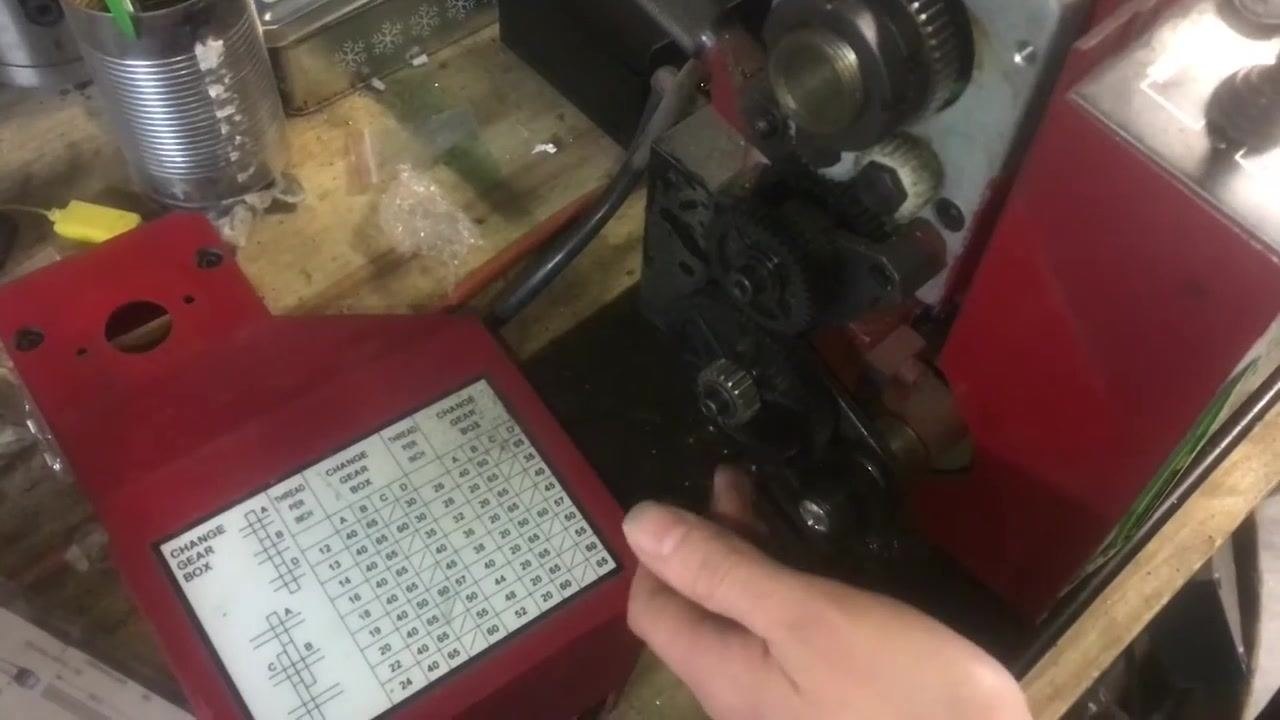
- Adjust the gear engagement and banjo position. Identify the bolts on the gear train assembly and at the back of the banjo (the arm holding the gears). Loosen these bolts to allow the shaft and banjo to move in and out and up and down. Move the banjo to achieve full tooth engagement between all gears, and ensure gear D can be flipped to engage with gear C instead of gear B, if your setup requires it.
-
Fine-tune the gear mesh. With the bolts loosened, carefully adjust the banjo position so all gears mesh smoothly without excessive play or binding, then tighten the bolts once the gears are properly engaged.
-
Change the lead screw direction, if needed. Locate the reversing lever near the top of the gear train and pull the handle back to move the mechanism. This adds or removes a gear from the train, reversing the lead screw direction. Set the lever to the position required for your threading operation.
-
Confirm the new gear arrangement. Observe the gear train after adjusting the reversing lever to ensure all gears are properly engaged and the lead screw rotates in the intended direction. Use an Allen key or wrench to secure any bolts that need further tightening.
-
Engage the half-nut and check gear movement. Engage the half-nut lever on the carriage to connect the lead screw to the carriage feed. Slowly turn the spindle by hand and observe all gears moving down to the lead screw, confirming that the lead screw is driving the carriage as expected.
-
Cover the gear train for safety. Replace the gear cover over the gear train to prevent debris or clothing from getting caught in the gears, and secure it with the appropriate screws or bolts.
Safety note: Never change gears while the lathe is running, and always replace the gear cover before operating the lathe.
Align the threading tool
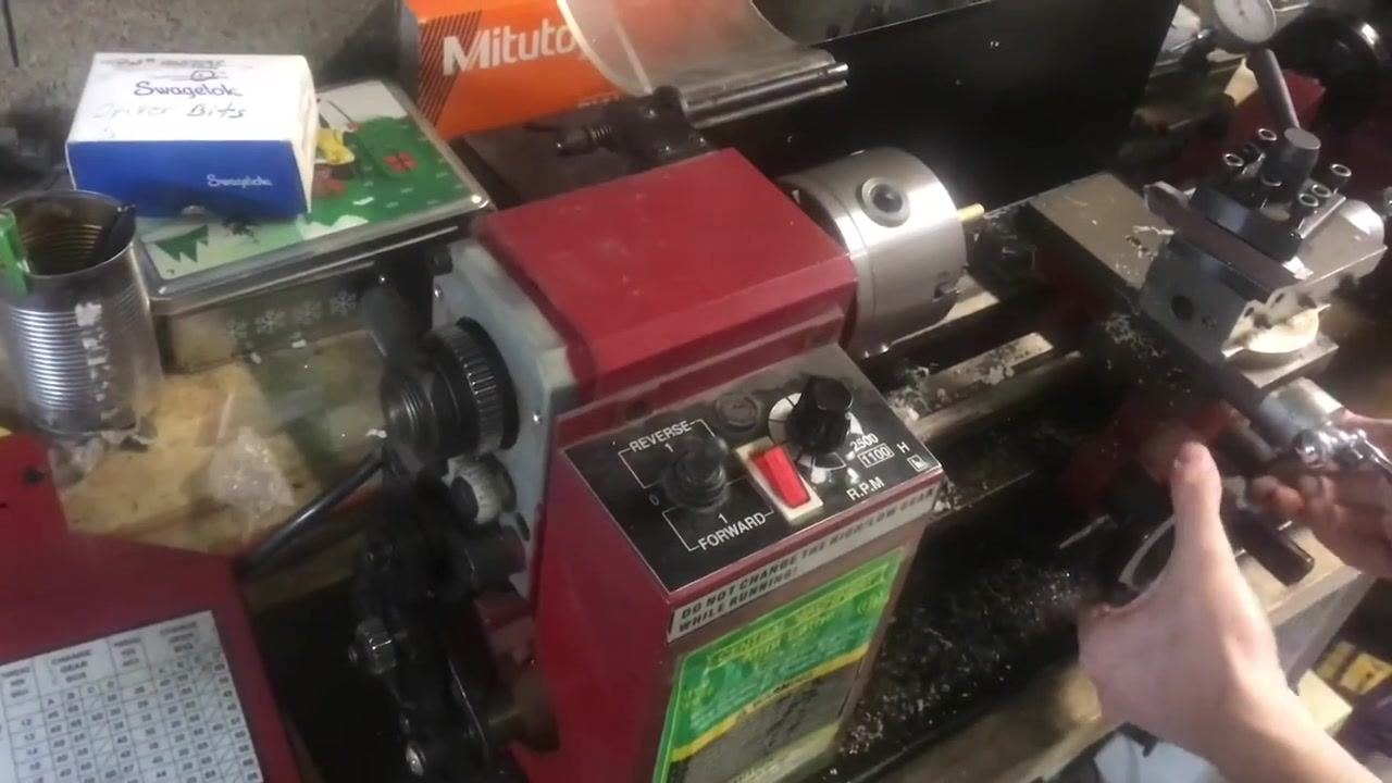
- Align the threading tool using a bolt if you do not have a fishtail gauge. Place a large standard bolt against the workpiece in the chuck, aligning it with the threads you intend to cut. Adjust the threading tool so it sits squarely in the thread groove of the bolt.
- Verify tool alignment. Inspect the setup to ensure the threading tool is correctly aligned with the bolt's threads, and make any necessary adjustments to the tool post or tool holder to achieve perfect alignment.
Set the compound rest angle
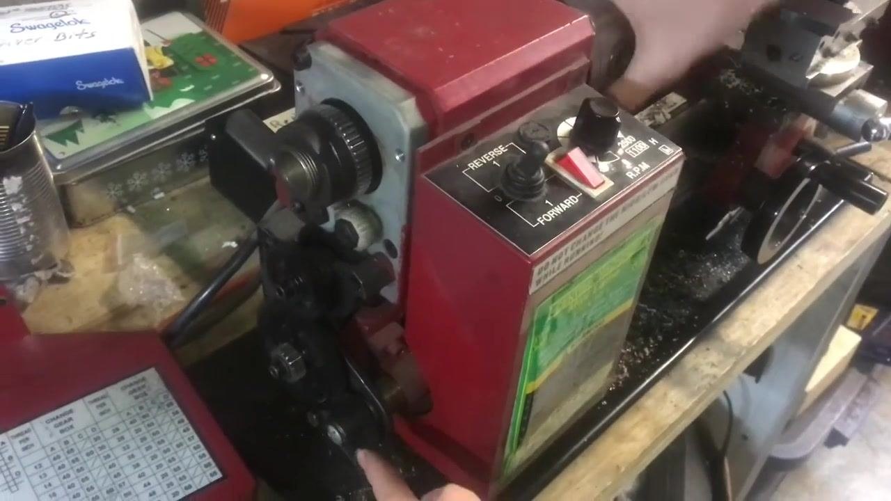
- Verify threading tool orientation. Inspect the threading tool to ensure its 60-degree point is correctly positioned in the workpiece and aligned as needed for the thread profile.
-
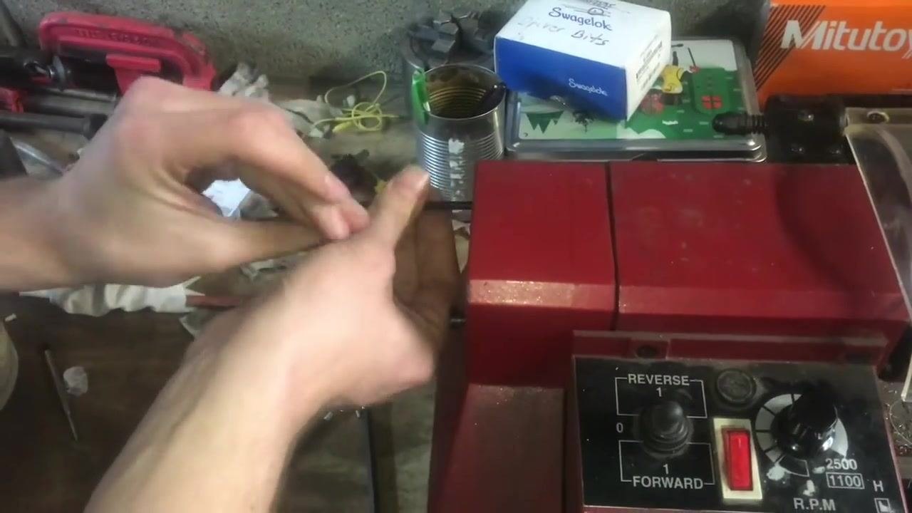
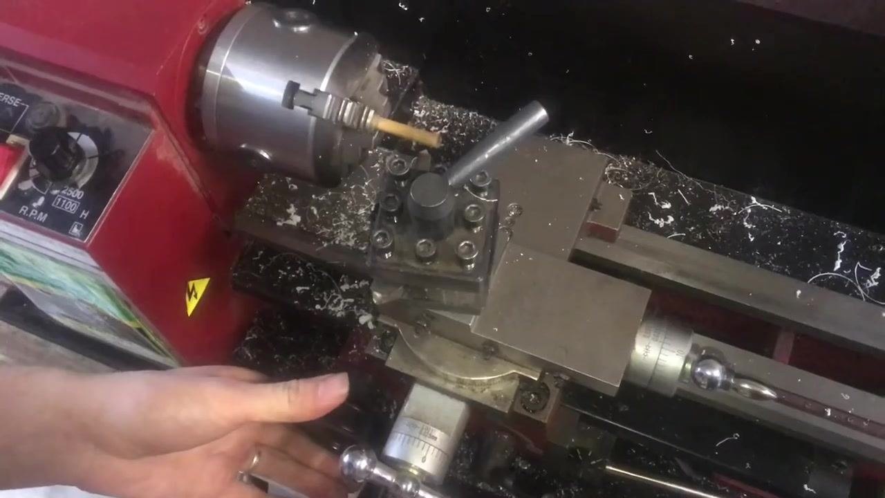
Set the compound rest angle, if needed. For precise threading, especially in metal, rotate the compound rest to approximately a 29.5-degree angle from straight. For soft materials like wood, you may leave the compound rest straight and feed directly in. Decide on the approach based on your material and precision needs.
-
Adjust the compound rest, if setting an angle. Loosen the compound rest locking screws, rotate the compound rest to 29.5 degrees from the cross-slide axis, and tighten the locking screws to secure the rest at the desired angle. The rest can also be left straight for wood threading.
-
Confirm the correct threading angle. Use your hand to visually indicate the 29.5-degree angle from straight as a reference for proper setup.
-
Prepare a relief groove (thread runout). Plan to cut a relief groove at the end of the thread to allow the tool to exit cleanly. Mark or note the location where the relief will be placed, typically at the back end of the threading area, so you can thread up to the relief without damaging the workpiece.
Use the thread dial and engage the half-nut
-
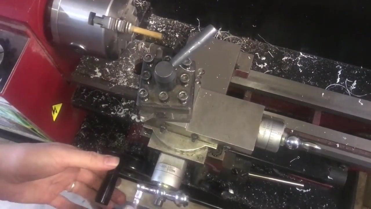
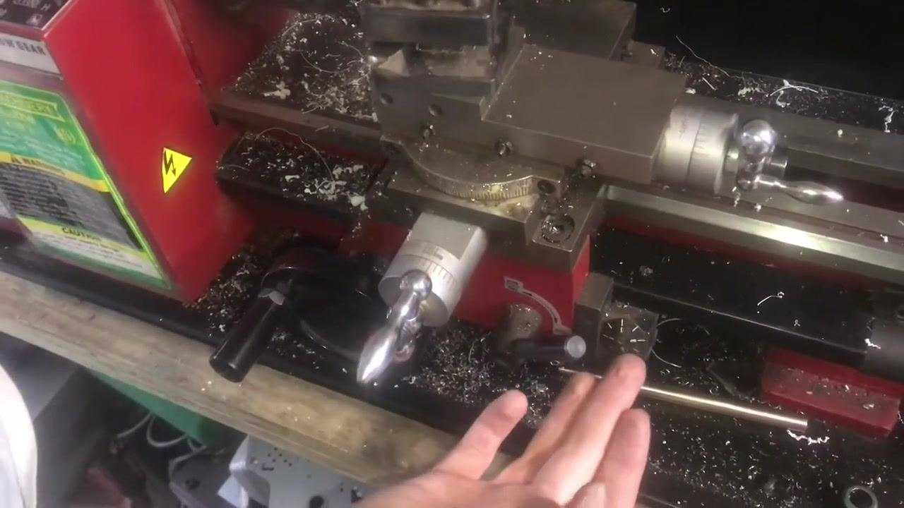
Understand thread dial operation. Turn on the lathe with the half-nut disengaged and observe the thread dial spinning, since the carriage is not engaged with the lead screw. Move the carriage to a visible position to monitor the dial.
-
Engage the half-nut for threading. Engage the half-nut lever at a specific mark on the thread dial (for example, at "1") to synchronize the carriage with the lead screw. When the half-nut is engaged, the thread dial stops spinning and the carriage begins to move with the lead screw, ensuring accurate thread timing and repeatability for each pass.
-
Practice timing with the thread dial. Engaging the half-nut at the correct dial position achieves consistent thread starts, which is essential for cutting threads that require multiple passes and precise alignment.
-
Confirm thread dial and carriage movement. Double-check that the thread dial stops and the carriage moves only when the half-nut is engaged, confirming the mechanism is functioning correctly for threading operations.
-
Engage the half-nut lever at the correct thread dial mark. Turn on the lathe and observe the thread dial as it rotates. Wait for the dial to reach the "1" mark, then engage the half-nut lever to synchronize the carriage with the lead screw. This ensures the threading tool starts its pass at the correct position for consistent thread pitch. Use one hand to operate the lathe controls and the other to engage the half-nut lever, and confirm that the carriage begins moving along the bed, indicating successful engagement.
Safety note: Always monitor the thread dial and engage the half-nut lever at the designated mark for each threading operation.
Pick up and cut threads on the workpiece
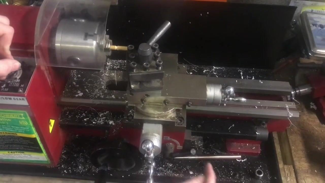
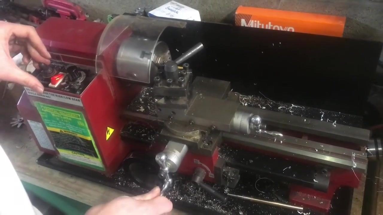
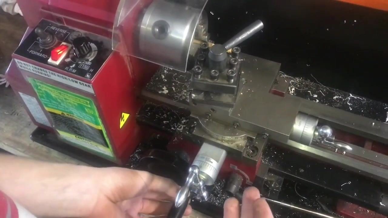
- Set up the lathe for threading. Ensure the lathe is clean and free of obstructions. Place the workpiece securely in the chuck and confirm the tool post is set up with the cutting tool aligned to the workpiece. Set the lathe to the correct threading speed and direction (Forward or Reverse as needed) and check that the gear settings match the desired thread pitch. Observe the control panel for the Forward/Reverse switch, RPM dial, and gear selector.
- Identify the thread pickup position. Rotate the carriage handwheel to position the cutting tool at the starting point of the thread. Use the thread dial or visual alignment to ensure you are picking up the same thread start position on each pass.
- Engage the half-nut lever at the correct position. Carefully engage the half-nut lever when the thread dial aligns with the correct mark, ensuring the tool follows the same thread path as previous passes.
-
Cut the thread and monitor progress. Start the lathe and allow the tool to cut along the thread path. Let the carriage travel until the tool reaches the relief area at the end of the thread, then turn off the lathe once the relief is reached.
-
Inspect the initial thread pass. After the scratch pass, visually inspect the beginnings of the thread on the workpiece and use a thread gauge to check the pitch and alignment of the cut.
- Continue cutting to full depth. If the thread pitch and alignment are correct, proceed with additional passes to reach the desired thread depth. Adjust the cross-slide or compound rest to increase the depth of cut incrementally, repeating the threading process and engaging the half-nut at the same dial position each time. Observe the thread forming more clearly with each pass.
Safety note: Always wear eye protection and keep hands clear of moving parts during operation. Never change gears while the lathe is running.
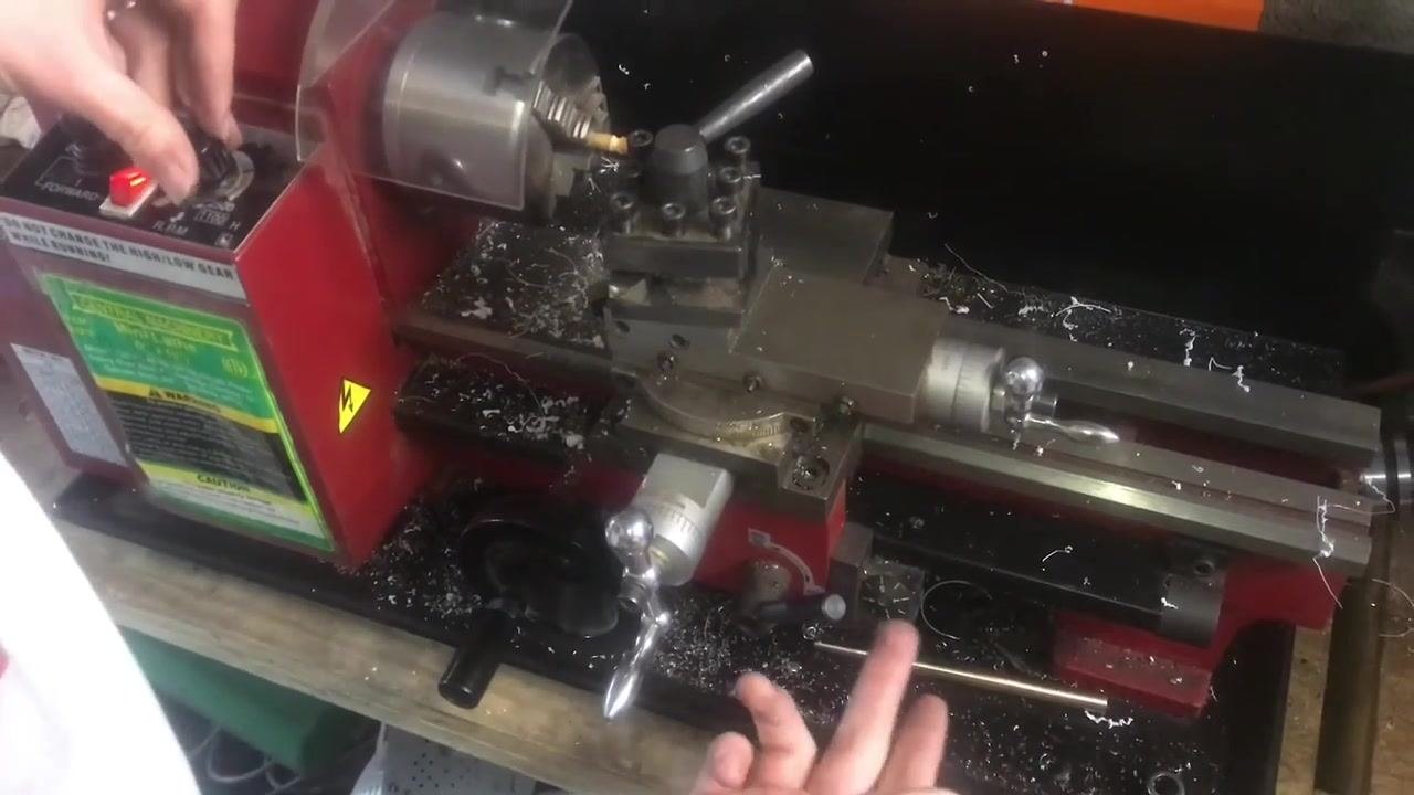
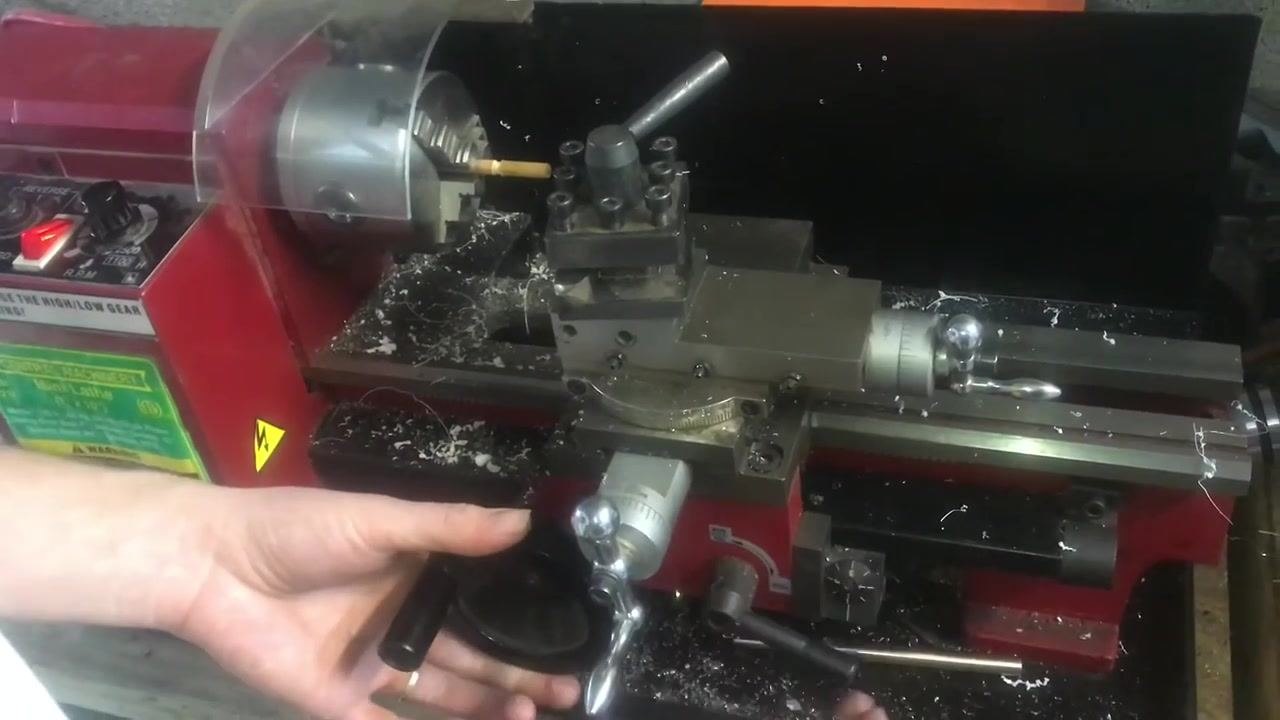
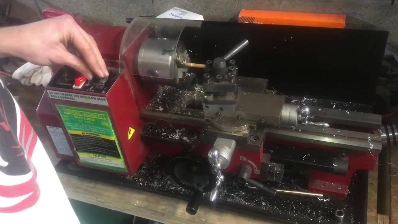
Reverse, retract, and adjust depth between passes
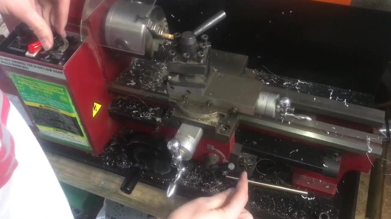
- Disengage the half-nut lever and return the carriage. If you need to return the carriage to the starting point after a threading pass, pull the half-nut lever up to disengage it and move the carriage (Z-axis) back to the thread starting position.
-
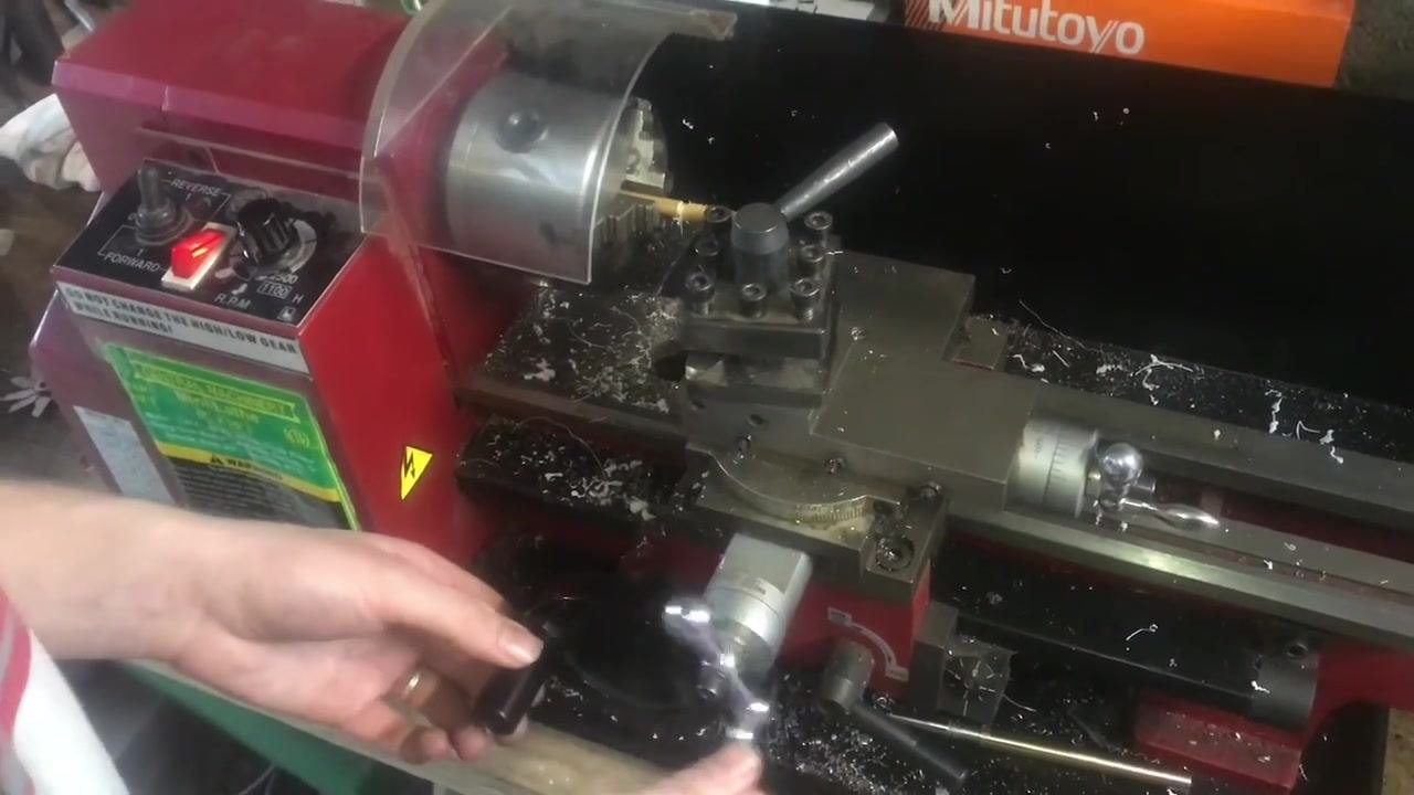
Retract the cutting tool using the X-axis. If your lathe allows reversing, you can retract the cutting tool along the X-axis (cross-slide) instead of moving the carriage back. Use the cross-slide handwheel to move the tool away from the workpiece.
-
Set up for the next threading pass. With the tool retracted, use the carriage handwheel to return the carriage to the starting position, with one hand on the control panel and the other on the carriage handwheel.
-
Increase the depth of cut for the next pass. Refer to the thread dial to confirm alignment for the next pass, then adjust the cross-slide or compound rest to increase the depth of cut slightly.
-
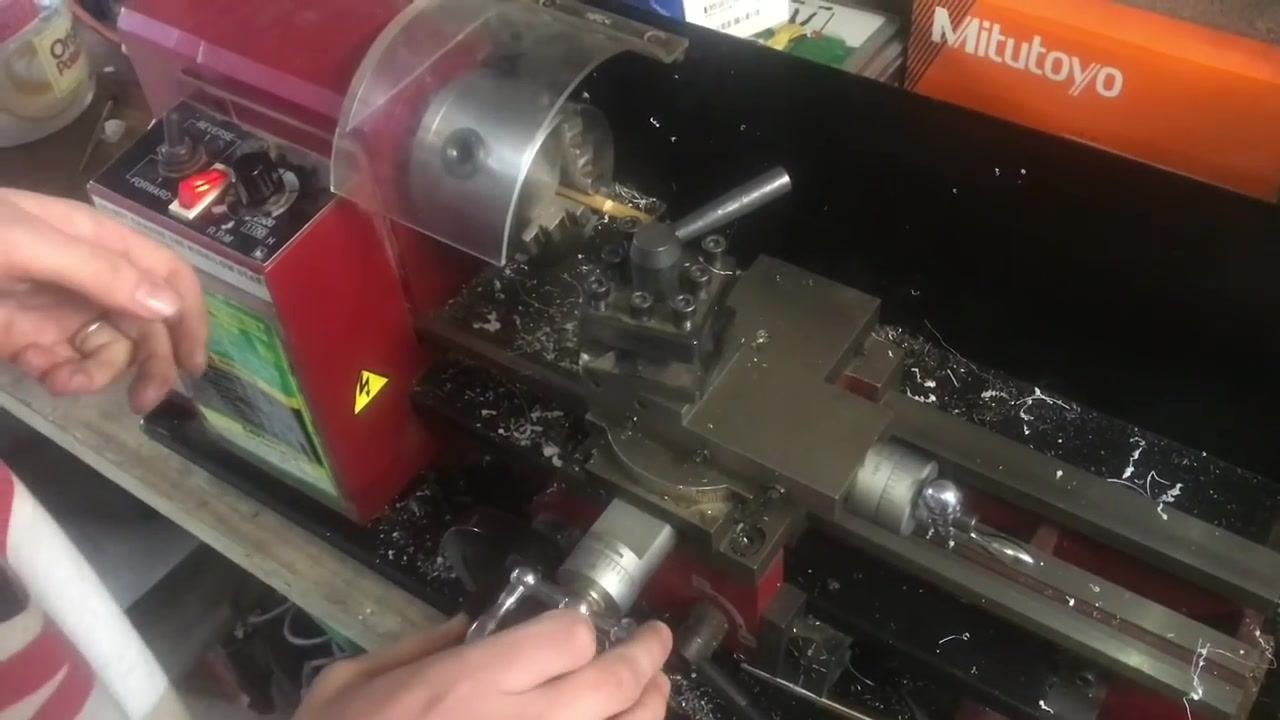
Feed the tool for another threading pass. Typically, feed the tool in the direction of the thread; feeding forward is also demonstrated for simplicity. Keep both hands on the carriage and cross-slide handwheels, ready to begin another pass.
- Engage forward and begin the next pass. After setting the new depth, switch the lathe back to Forward if needed. Ensure the half-nut is engaged, turn on the lathe to begin the next threading pass, and stop the carriage in the relief area at the end of the thread.
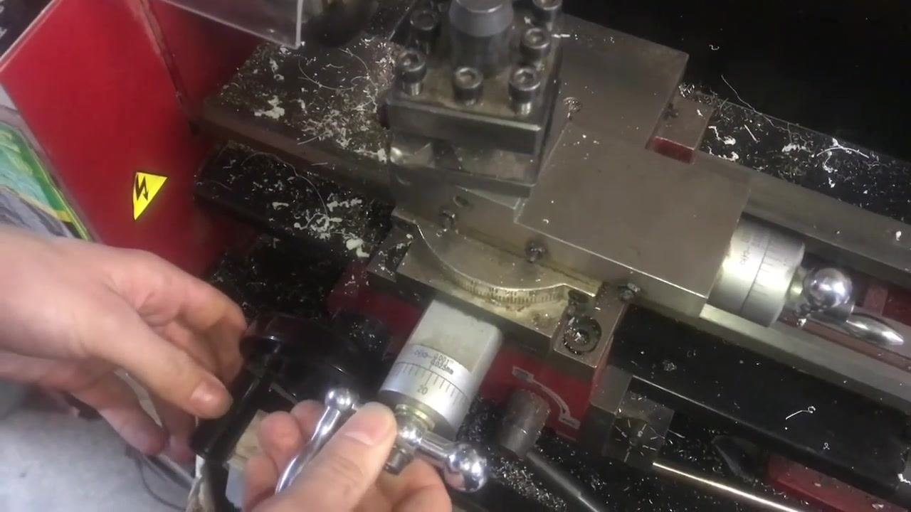
- Monitor thread depth and reverse if needed. If the thread needs to be deeper, note the dial reading (for example, "20") before backing out the tool. Retract the tool, then switch the lathe to Reverse to return to the starting position without disengaging the half-nut.
-
Fine-tune and inspect the thread. Continue adjusting the depth and making passes as needed, closely monitoring the dial and handwheel to ensure precise adjustments.
-
Observe material behavior. Different materials, such as wood versus metal or plastic, may chip or cut differently. Wood, for example, may chip out more than expected, which will be visible in the work area.
Safety note: Always keep hands clear of moving parts and ensure the lathe is stopped before making adjustments. Use eye protection and follow all shop safety protocols.
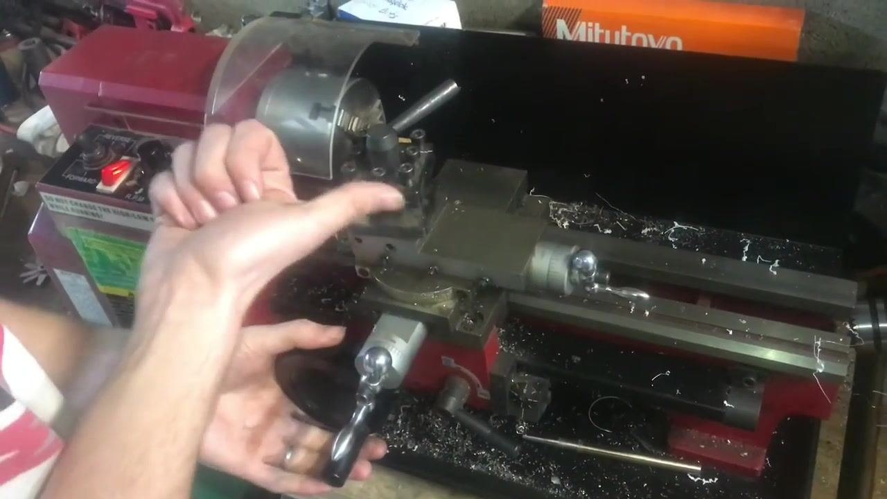
Complete final threading passes and inspect the result
- Observe the thread formation and material quality. Watch the cutting process as the tool forms threads on the workpiece, with the lathe running in Forward mode as indicated by the illuminated switch on the control panel. Note that other materials may produce a cleaner cut than wood, but the threads will still form correctly.
-
Continue cutting to the desired thread depth. Allow the tool to continue cutting along the length of the workpiece, forming a continuous line of thread. Adjust the cross-slide or compound rest as needed to reach the required depth, and monitor progress visually to ensure the threads are forming evenly.
-
Fine-tune the thread depth and check the fit. Use the cross-slide handwheel to make fine adjustments to the tool position, ensuring the pitch diameter is correct so the thread depth matches the requirements for the mating part to fit smoothly.
-
Perform a final inspection with a thread gauge. Stop the lathe and use a thread pitch gauge to check the accuracy of the threads. Hold the gauge against the newly cut threads to verify the pitch and profile.
Safety note: Always stop the lathe before performing inspections or measurements. Keep hands clear of moving parts and wear appropriate eye protection throughout the process.
Verification and summary
Confirm the following before considering the threading job complete:
- The gear train is configured to match the threading chart for the desired TPI, and the gear cover is secured.
- The threading tool is aligned squarely with the thread groove, using a fishtail gauge or bolt reference.
- The compound rest is set to the correct angle (or left straight for softer materials) as required by the material and precision needed.
- The half-nut engages consistently at the same thread dial mark on every pass.
- The thread has been cut in incremental passes, checked with a thread gauge, until the required depth and pitch are achieved.
- The final thread has been verified with a thread pitch gauge for accuracy and fit against the mating part.
Safety note: Always wear eye protection, keep hands clear of moving parts, never change gears while the lathe is running, and stop the lathe before making measurements or adjustments.
Generation details: cost, quality tiers
Docsie billed 5,000 credits ($3.50) to analyze this 10-minute video at standard quality. The rewrite, template fill and Word/PDF exports were included. The same video at each quality tier:
| Quality | Frames sampled | Credits | Approx. cost |
|---|---|---|---|
| Draft | every 16-30 s | 2,500 | $1.75 |
| Standard (this guide) | every 8-15 s | 5,000 | $3.50 |
| Detailed | every 4-7 s | 10,000 | $7.00 |
| Ultra | every 1-3 s | 20,000 | $14.00 |
Credits priced at $0.70 per 1,000; plans include a monthly allowance. Enterprise customers on on-premise or bring-your-own-model deployments run this on their own inference and pay no per-video credits.
Generated by Docsie Video-to-Docs on 2026-09-14 from a 9-minute video. Screenshots are frames from the source video and belong to their creator, Live Free, whose original is embedded above. If you own this video and want the guide removed or credited differently, contact us and we will act within one business day.