
How to Connect an Hmi to a PLC
This standard operating procedure explains how to connect an HMI to a PLC using Siemens TIA Portal V14 SP1. It covers creating a new PLC project, adding a PLC device and programming basic ladder logic, adding an HMI panel, linking HMI tags to PLC tags, configuring screen animations, and downloading and verifying the configuration using the HMI Runtime Simulator. Follow the steps in order to establish a working communication link between a SIMATIC S7-1200 PLC and a SIMATIC KTP700 Basic Panel HMI.
Video: HMI-PLC connection configuration in Siemens TIA Portal by TechJourneyHub (2024). All credit for the demonstration goes to the creator; watch the original on YouTube. The written guide below was generated from this video by Docsie. Creator? Request a change or removal.
This standard operating procedure explains how to connect an HMI to a PLC using Siemens TIA Portal V14 SP1. It covers creating a new PLC project, adding a PLC device and programming basic ladder logic, adding an HMI panel, linking HMI tags to PLC tags, configuring screen animations, and downloading and verifying the configuration using the HMI Runtime Simulator. Follow the steps in order to establish a working communication link between a SIMATIC S7-1200 PLC and a SIMATIC KTP700 Basic Panel HMI.
Purpose
The purpose of this procedure is to provide a repeatable method for connecting an HMI to a PLC in TIA Portal, from initial project creation through to runtime verification of the HMI-PLC link.
Scope
This procedure applies to engineers configuring a SIMATIC S7-1200 PLC and a SIMATIC KTP700 Basic Panel HMI in TIA Portal V14 SP1. It covers project setup, device addition, ladder logic programming, HMI-PLC communication configuration, tag linking, screen animation, and simulation-based verification.
Required software and equipment
- Siemens TIA Portal V14 SP1
- SIMATIC S7-1200 controller, CPU 1214C DC/DC/DC (Article no.: 6ES7 214-1AG40-0XB0, Version: V4.2)
- SIMATIC Basic Panel, KTP700 Basic PN (Article no.: 6AV2 123-2GB03-0AX0, Version: 14.0.1.0)
- PLCSIM for PLC simulation
- HMI Runtime (RT) Simulator for HMI testing
Procedure
Section 1: Create and configure the PLC project
- Start a new project
- Open Siemens TIA Portal.
- In the left navigation pane, select Create new project.
- Enter the following details in the "Create new project" form:
- Project name: HM_CONNECTION
- Path: C:\Users\mgork\Desktop
- Version: V14 SP1
- Author: mgork
- Comment: leave blank
- Click Create.
- Wait for the "Creating project..." dialog to finish. The project is created at
C:\Users\mgork\Desktop\HM_CONNECTION\HM_CONNECTION.ap14.
-
Access the project workspace
- Once the project is created, the main workspace opens.
- The Project tree on the left shows the project structure.
- The Window menu is open, displaying options for window layouts and editor navigation.
- The Tasks pane on the right provides options such as "Find and replace".
- Confirm that the project "HM_CONNECTION" is active and visible in the title bar.
-
Add a new device (PLC)
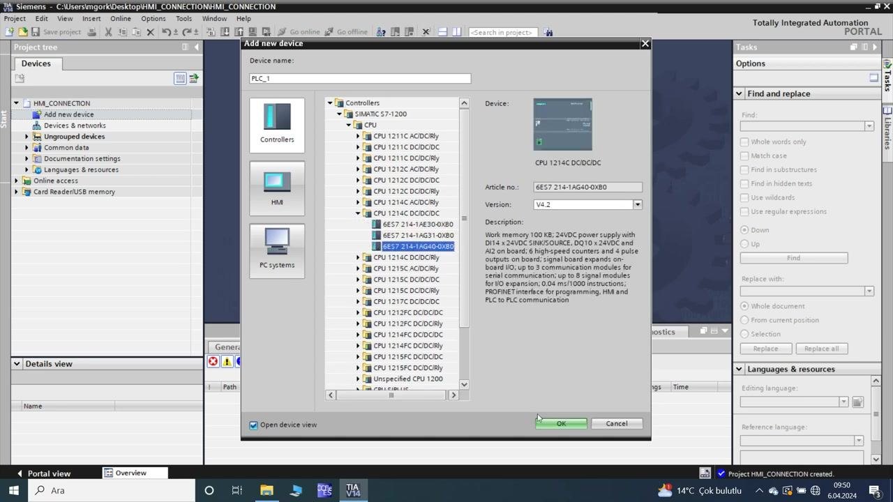
- In the Project tree, select Add new device under "HM_CONNECTION".
- In the "Add new device" dialog:
- Device name: PLC_1
- Under Controllers, expand SIMATIC S7-1200 > CPU.
- Select CPU 1214C DC/DC/DC (Article no.: 6ES7 214-1AG40-0XB0, Version: V4.2).
- Review the device description on the right.
- Ensure Open device view is checked.
- Click OK to add the device.
-
View and confirm the device configuration
- The Device view opens, displaying the PLC rack layout.
- The selected CPU (PLC_1) is placed in slot 1 of Rack_0.
- The Project tree now lists "PLC_1 [CPU 1214C DC/DC/DC]" under "Devices".
- The Hardware catalog is visible on the right for adding modules.
- Confirm the correct CPU is added and visible in the rack.
- Open the main program block for PLC logic
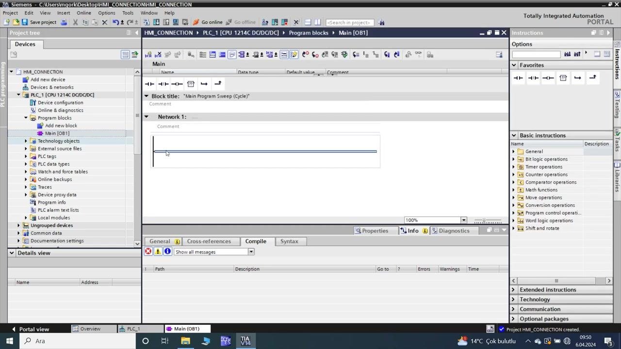
- In the Project tree, expand "PLC_1 [CPU 1214C DC/DC/DC]" > "Program blocks".
- Double-click Main [OB1] to open the main program sweep (cycle) block.
- The logic editor opens with "Network 1" ready for programming.
- The Instructions pane on the right provides basic instructions (bit logic, timers, counters, etc.).
- Insert and edit ladder logic
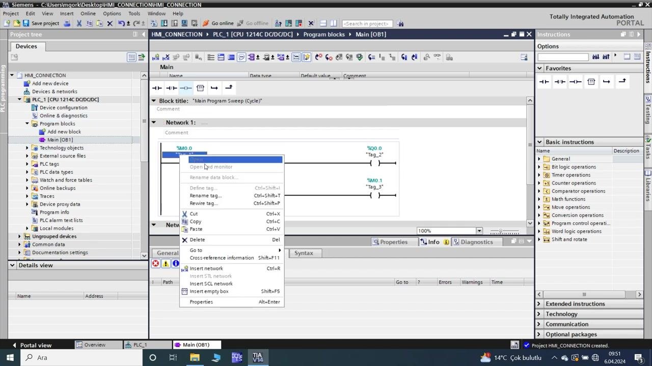
- In the logic editor, insert a rung in "Network 1".
- Add a normally open contact and a coil.
- Assign the following addresses and tags:
- Contact:
%M0.0(tag: HM_BUTTON) - Coil:
%Q0.0(tag: Tag_2) - Coil:
%M0.1(tag: Tag_3)
- Contact:
- The rung connects
%M0.0to%Q0.0and%M0.1.
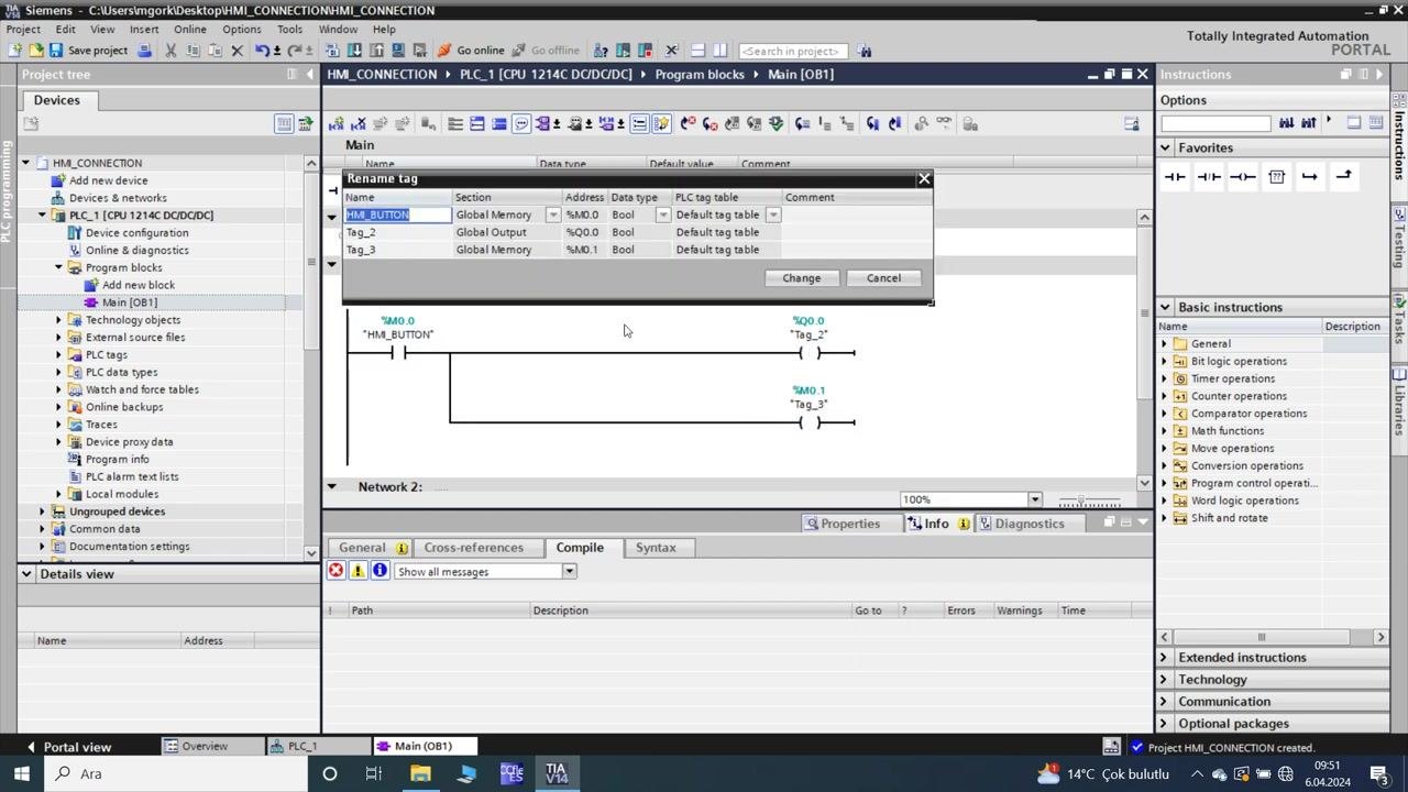
- Edit tag names and properties
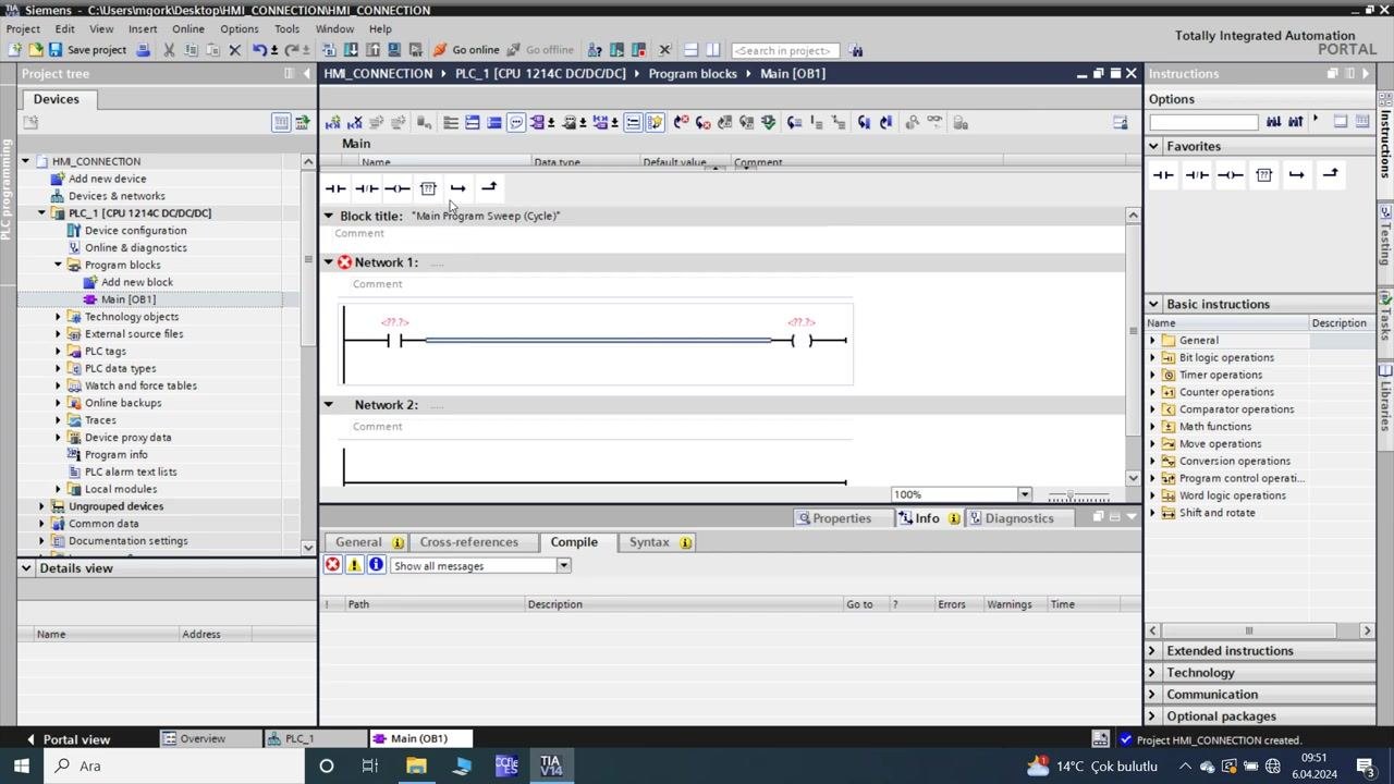
- Right-click on a tag (for example
%M0.0) in the ladder logic. - Select Open or Rename tag from the context menu.
- In the "Name tag" dialog, edit the tag names and properties:
%M0.0→ Name: HM_BUTTON, Section: Global Memory, Data type: Bool%Q0.0→ Name: Tag_2, Section: Global Output, Data type: Bool%M0.1→ Name: Tag_3, Section: Global Memory, Data type: Bool
- Click Change to apply the edits.
- Right-click on a tag (for example
- Finalize and review the ladder logic
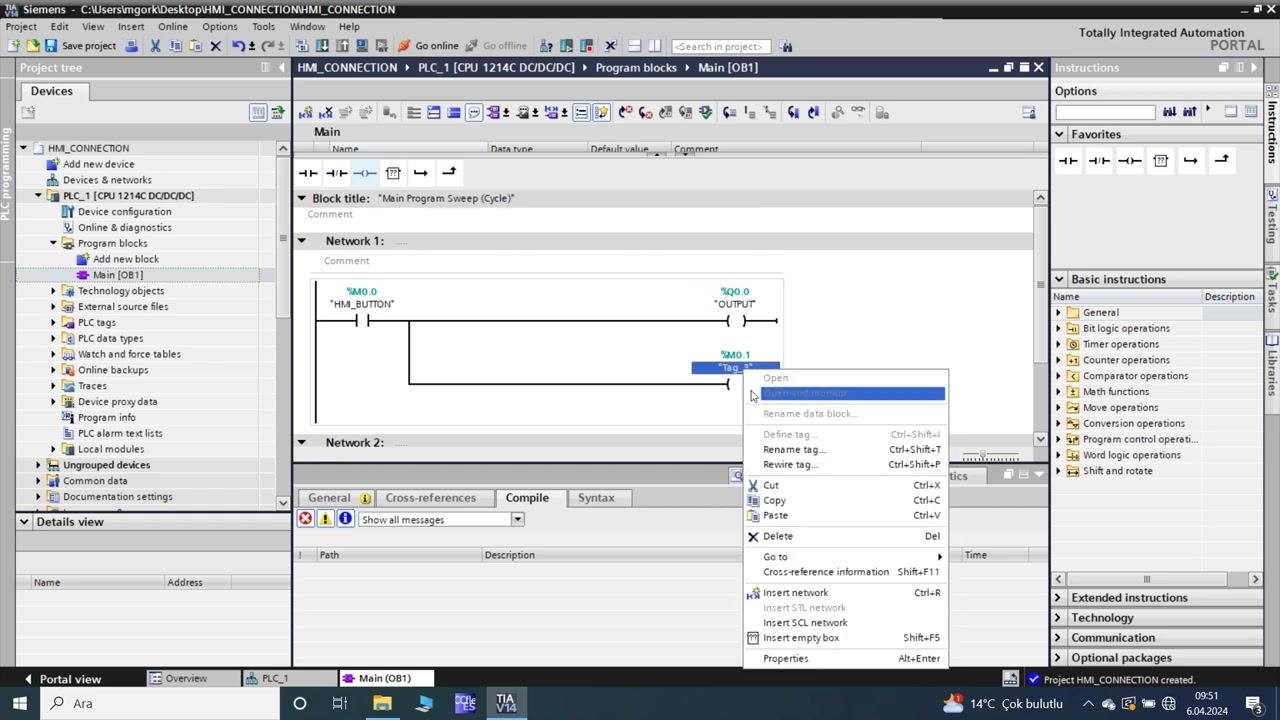
- Confirm the ladder logic now displays:
%M0.0labeled "HM_BUTTON"%Q0.0labeled "OUTPUT"%M0.1labeled "Tag_3"
- Right-click on tags as needed to further edit or monitor them.
- Confirm the ladder logic now displays:
Section 2: Add the HMI device and connect it to the PLC
- Rename a tag in the PLC program
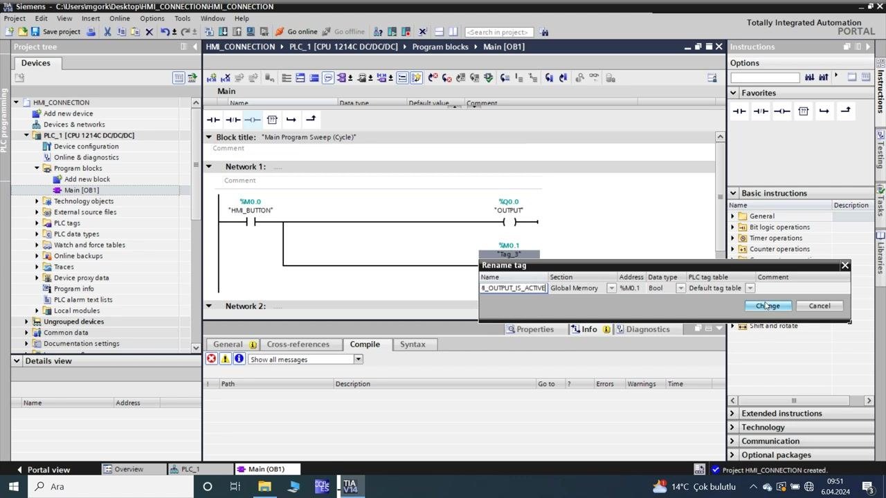
- In the Main [OB1] program block, right-click the
%M0.1tag (currently labeled "Tag_3"). - Select Rename tag from the context menu.
- In the "Rename tag" dialog, enter the new name:
HM_OUTPUT_IS_ACTIVE. - Confirm the section as Global Memory, the address as
%M0.1, and the data type as Bool. - Click Change to apply the new tag name.
- In the Main [OB1] program block, right-click the
- Verify updated tag names in the ladder logic
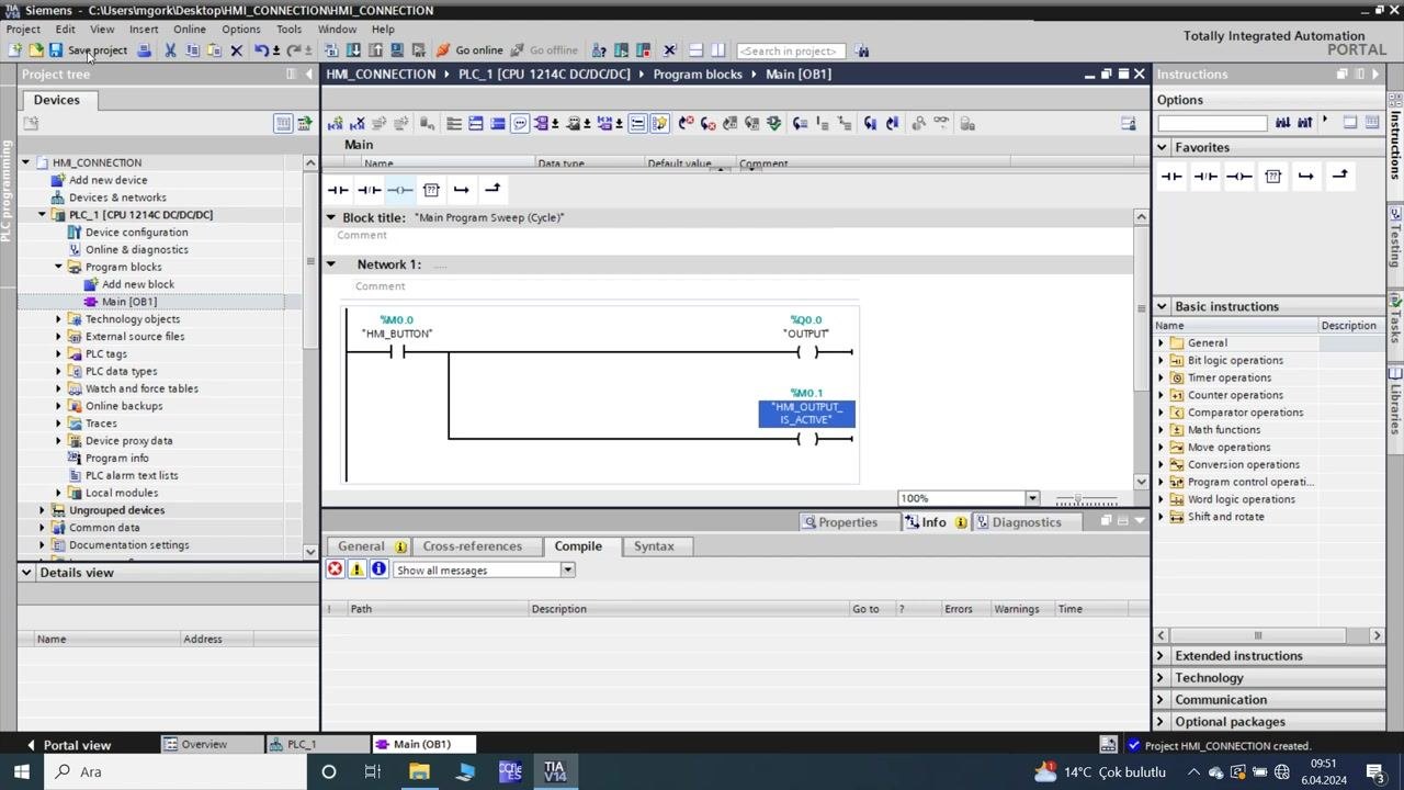
- Confirm that the ladder logic in Network 1 now displays:
%M0.0labeled "HM_BUTTON"%Q0.0labeled "OUTPUT"%M0.1labeled "HM_OUTPUT_IS_ACTIVE"
- The updated tag name is highlighted in the logic editor.
- Confirm that the ladder logic in Network 1 now displays:
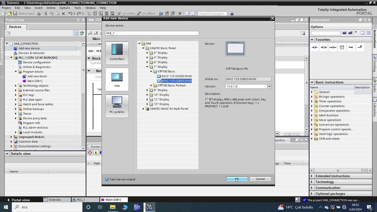
- Add a new HMI device
- In the Project tree, under "HM_CONNECTION", select Add new device.
- In the "Add new device" dialog:
- Set Device name: HM_1
- Under HMI, expand SIMATIC Basic Panel > KTP700 Basic.
- Select 6AV2 123-2GB03-0AX0 (KTP700 Basic PN).
- Confirm the device details:
- Article no.: 6AV2 123-2GB03-0AX0
- Version: 14.0.1.0
- Description: 7" TFT display, 800x480 pixel, 64K colors, key and touch operation, 8 function keys, 1x PROFINET, 1x USB.
- Click OK to add the HMI device.
-
Configure PLC-HMI communication to connect the HMI to the PLC
- The HMI Device Wizard opens for the KTP700 Basic PN.
- In the "PLC connections" step:
- Ensure the communication driver is set to SIMATIC S7 1200.
- Interface: PROFINET (X1)
- HMI device: HM_1 KTP700 Basic PN
- PLC device: PLC_1 CPU 1214C DC/DC/DC
- Click Next to proceed, or Finish if no further configuration is needed at this stage.
-
Verify HMI device addition
- In the Project tree, confirm that "HMI_1 [KTP700 Basic PN]" is now listed under "HM_CONNECTION".
- The HMI device configuration and screens are now accessible.
-
Open and edit the HMI root screen
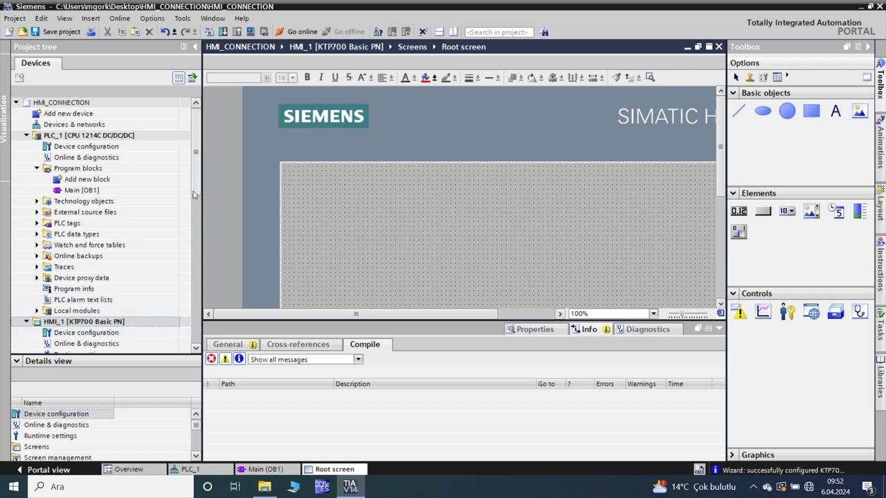
- In the Project tree, expand "HMI_1 [KTP700 Basic PN]" > "Screens".
- Double-click Root screen to open the HMI screen editor.
- The editor displays a blank grid with "SIEMENS" and "SIMATIC HMI" headers.
- The Toolbox on the right provides basic objects (rectangle, ellipse, line, button, text, etc.), elements, and controls for screen design.
- Manage HMI screens
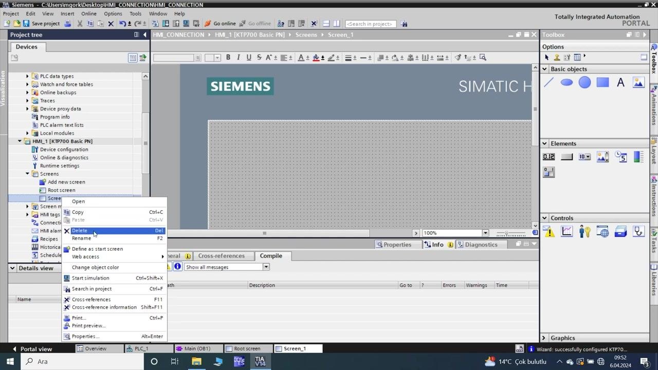
- In the Project tree, right-click on "Screen_1" under "Screens".
- A context menu appears with options: Open, Copy, Paste, Delete, Rename, Define as start screen, Web access, Change object color, Start simulation, Search in project, Cross-references, Print, Properties, etc.
- Select Delete to remove the unnecessary screen.
- Set the start screen for HMI runtime
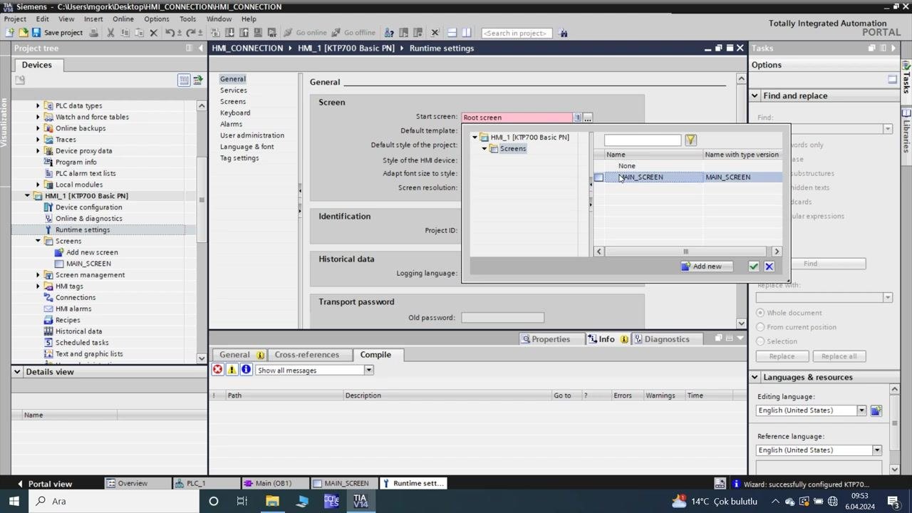
- In the Project tree, select "Runtime settings" under "HMI_1 [KTP700 Basic PN]".
- In the "General" tab, under "Screen", set the Start screen.
- In the dialog, select MAIN_SCREEN from the list of available screens.
- Click the checkmark to confirm the selection.
-
Design the main HMI screen
- In the Project tree, double-click MAIN_SCREEN under "Screens" to open it in the editor.
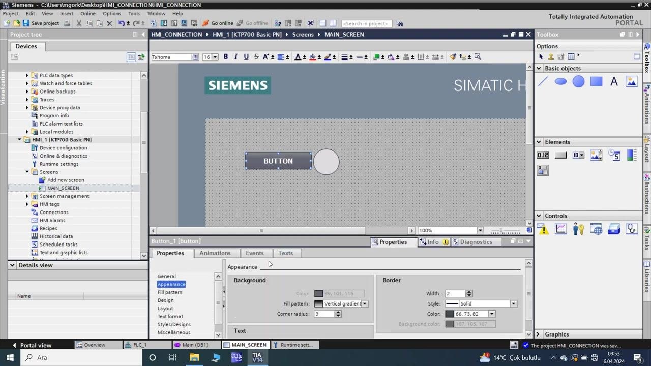
- Add a button to the screen. The button appears with the default label "Text".
- The screen displays the SIEMENS and SIMATIC HMI headers, and the button is centered on the grid.
-
Edit button properties and add an indicator
- Select the button on the MAIN_SCREEN.
- In the Properties pane (bottom), adjust the appearance:
- Change the button label to "BUTTON".
- Modify background color, border, and other appearance settings as needed.
- Add a circular indicator (ellipse) next to the button.
- The screen now shows a button labeled "BUTTON" and a circular indicator beside it.
Section 3: Create and link HMI tags to PLC tags
- Review the main HMI screen layout
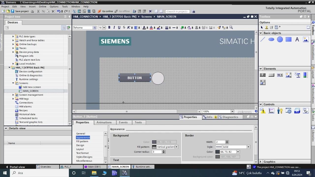
- In the HMI screen editor, confirm the MAIN_SCREEN layout:
- The screen displays the "SIEMENS" and "SIMATIC HMI" headers.
- A button labeled "BUTTON" is placed on the grid, with a circular indicator (ellipse) next to it.
- The Properties pane at the bottom is open, showing the Appearance settings for the selected button.
- In the HMI screen editor, confirm the MAIN_SCREEN layout:
-
Open the HMI tag table for tag creation
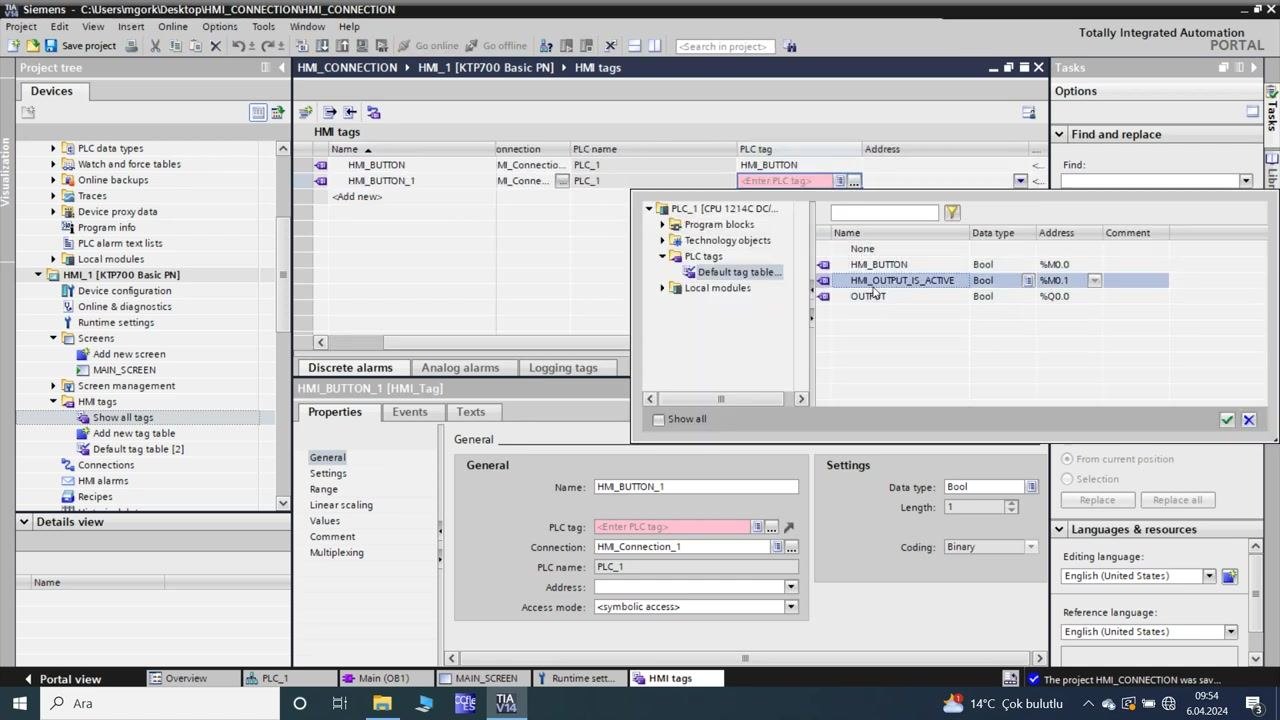
- In the Project tree, under "HMI_1 [KTP700 Basic PN]", expand "HMI tags" and select "Show all tags".
- The HMI tags table appears in the main workspace.
- The "Add new tag" row is visible, and the Properties pane below is ready for tag configuration.
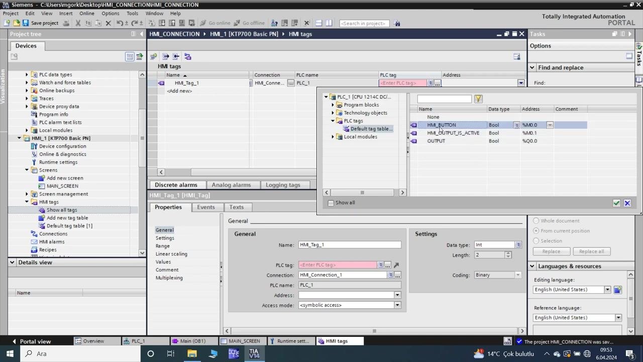
- A dialog for selecting a PLC tag opens, showing the available PLC tag tables and modules.
-
Browse and select PLC tags for HMI tag linking
- In the PLC tag selection dialog, expand "PLC_1 [CPU 1214C DC/DC/DC]" > "PLC tags" > "Default tag table".
- The following PLC tags are visible:
- HM_BUTTON (Bool, %M0.0)
- HM_OUTPUT_IS_ACTIVE (Bool, %M0.1)
- OUTPUT (Bool, %Q0.0)
- Select "HM_BUTTON" to link it to the HMI tag.
- Configure HMI tag properties
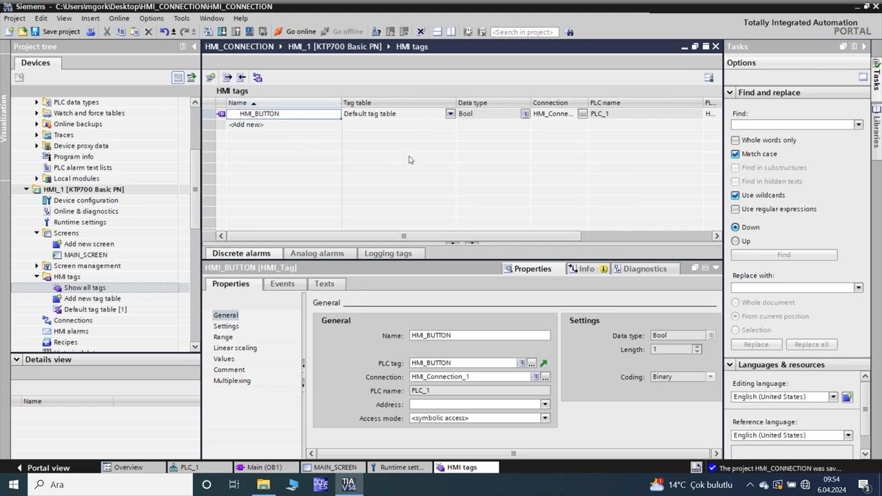
- In the HMI tags table, confirm the following for the new tag:
- Name: HM_BUTTON
- Tag table: Default tag table
- Data type: Bool
- Connection: HM_Connection_1
- PLC name: PLC_1
- PLC tag: HM_BUTTON
- Address: auto-filled
- Access mode:
- The Properties pane below displays these details for verification.
- In the HMI tags table, confirm the following for the new tag:
- Add and link a second HMI tag
- In the HMI tags table, add a new tag with the following details:
- Name: HM_BUTTON_1
- Tag table: Default tag table
- Data type: Bool
- Connection: HM_Connection_1
- PLC name: PLC_1
- In the PLC tag selection dialog, select "HM_OUTPUT_IS_ACTIVE" to link it to the new HMI tag.
- Confirm the address and access mode are set correctly.
- In the HMI tags table, add a new tag with the following details:
- Set the HMI tag acquisition cycle
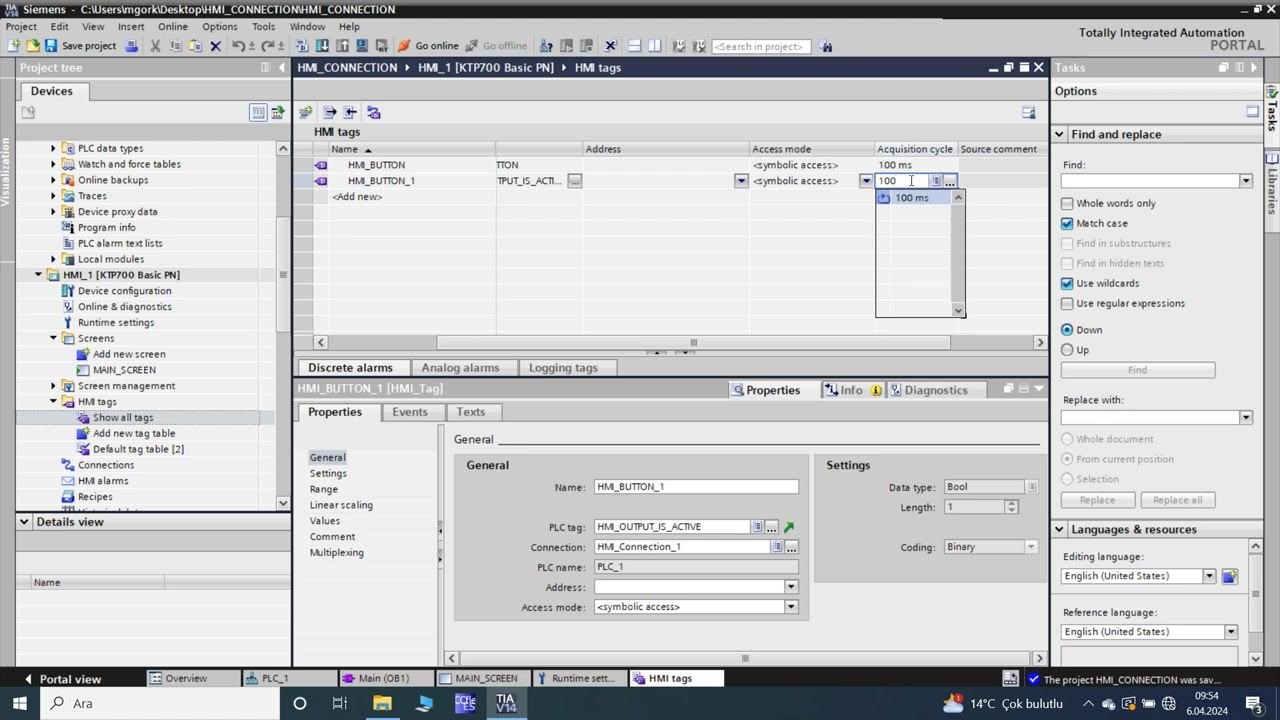
- In the HMI tags table, set the "Acquisition cycle" for each tag:
- For both HM_BUTTON and HM_BUTTON_1, set the acquisition cycle to 100 ms.
- This ensures the HMI reads tag values from the PLC every 100 milliseconds.
- In the HMI tags table, set the "Acquisition cycle" for each tag:
- Verify the HMI tag configuration
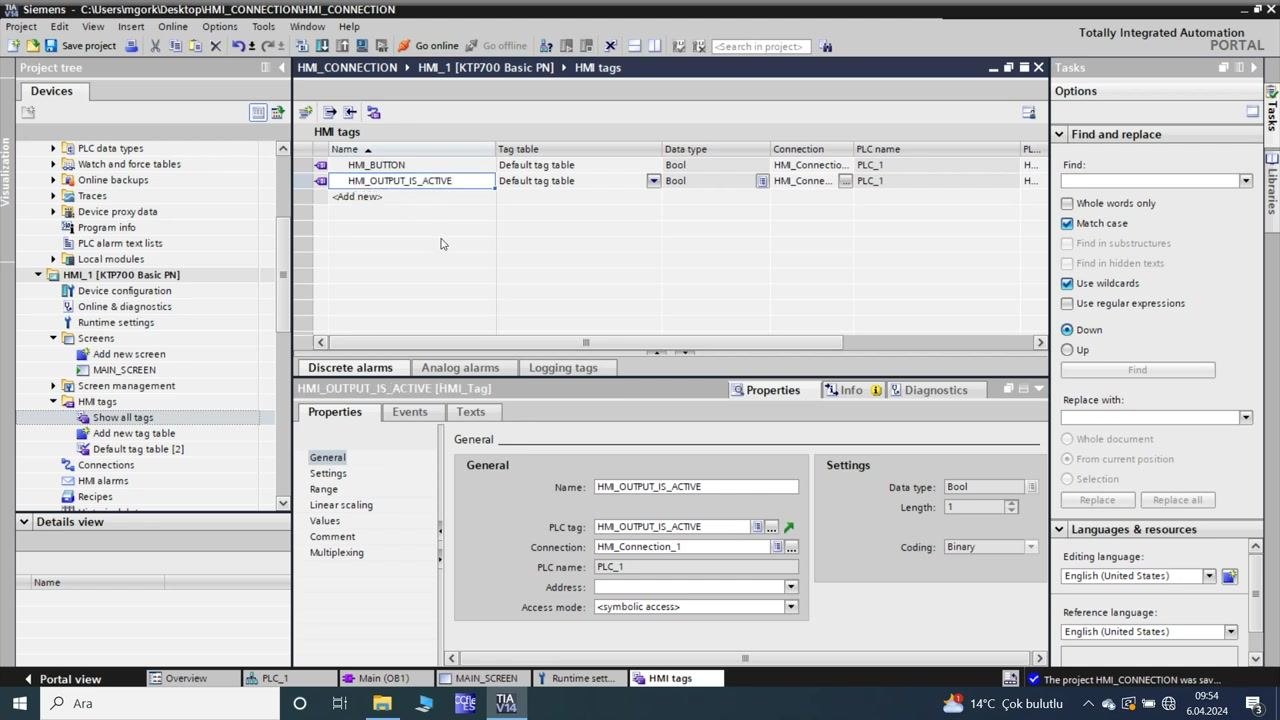
- Confirm that the HMI tags table now lists:
- HM_BUTTON (Bool, linked to PLC tag HM_BUTTON)
- HM_OUTPUT_IS_ACTIVE (Bool, linked to PLC tag HM_OUTPUT_IS_ACTIVE)
- Both tags are in the Default tag table, connected to PLC_1 via HM_Connection_1, with acquisition cycles set.
- Confirm that the HMI tags table now lists:
- Return to the HMI screen editor for button configuration
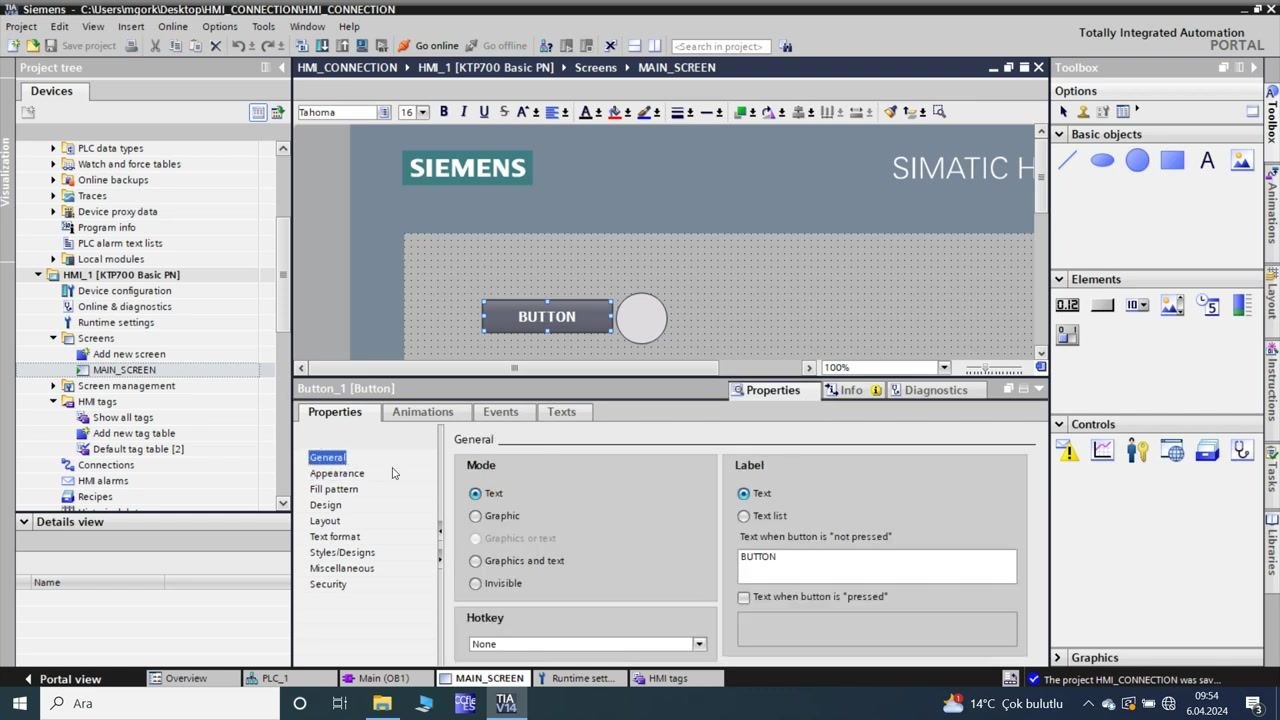
- Switch back to the MAIN_SCREEN in the HMI screen editor.
- Select the button labeled "BUTTON".
- In the Properties pane, open the "General" tab:
- Mode: Text
- Label: BUTTON (text when the button is "not pressed")
- Hotkey: None
- Configure button events to control the PLC tag
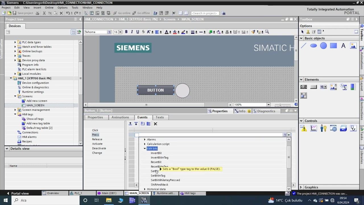
- With the button selected, open the "Events" tab in the Properties pane.
- Under the "Press" event, expand "Edit bits".
- Select the "SetBit" action (sets a Bool type tag to the value 1/TRUE).
- This action is used to write to the linked PLC tag when the button is pressed.
Section 4: Configure HMI button animations and tag connections
-
Navigate to the MAIN_SCREEN in the HMI screen editor
- Ensure you are in the "MAIN_SCREEN" of the HMI editor.
- The screen displays:
- "SIEMENS" header on the left.
- "SIMATIC HMI" header on the right.
- A button labeled "BUTTON" and a circular indicator (ellipse) next to it.
- The button is selected, indicated by a blue outline.
-
Access the button properties
- In the lower pane, confirm the "Properties" tab is selected for the button.
- The button is listed as "Button_1 [Button]" in the tab header.
-
Open the Animations tab
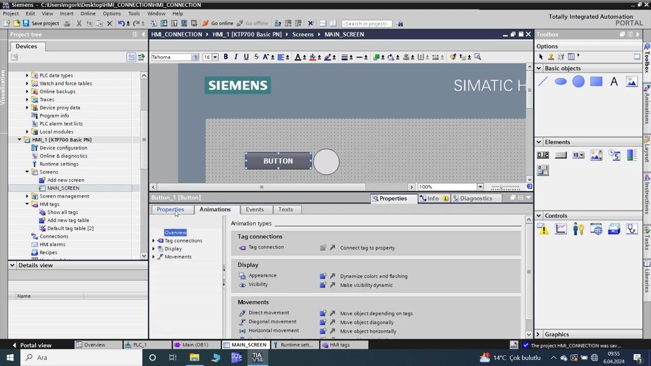
- Within the Properties pane, select the "Animations" tab.
- The Animations tab is divided into sections:
- Tag connections: allows linking tags to button properties.
- Display: options for dynamic appearance and visibility.
- Movements: options for direct, diagonal, and horizontal movement based on tag values.
-
Review animation types and options
- Under "Tag connections": the "Tag connection" option is available to connect a tag to a property.
- Under "Display":
- "Appearance": option to dynamize colors and flashing.
- "Visibility": option to make visibility dynamic.
- Under "Movements":
- "Direct movement": move the object depending on tags.
- "Diagonal movement": move the object diagonally.
- "Horizontal movement": move the object horizontally.
-
Prepare to link tags and configure animations
- Use the options in the Animations tab to:
- Connect HMI or PLC tags to button properties for dynamic behavior.
- Set up dynamic appearance or movement based on tag values.
- No tag is yet connected at this stage, but the interface is ready for configuration.
- Use the options in the Animations tab to:
Section 5: Configure HMI screen elements and animation
-
Open the main HMI screen for editing
- Ensure you are in the TIA Portal environment.
- In the project tree, navigate to
HMI_1 [KTP700 Basic PN] > Screens > MAIN_SCREEN. - The main workspace displays the HMI screen with a grid background, a "SIEMENS" logo, and a "SIMATIC HMI" label.
- A rectangular button labeled "BUTTON" and a circular object are present on the screen.
- The "Properties" pane is open at the bottom, showing settings for the selected object.
-
Set the button appearance
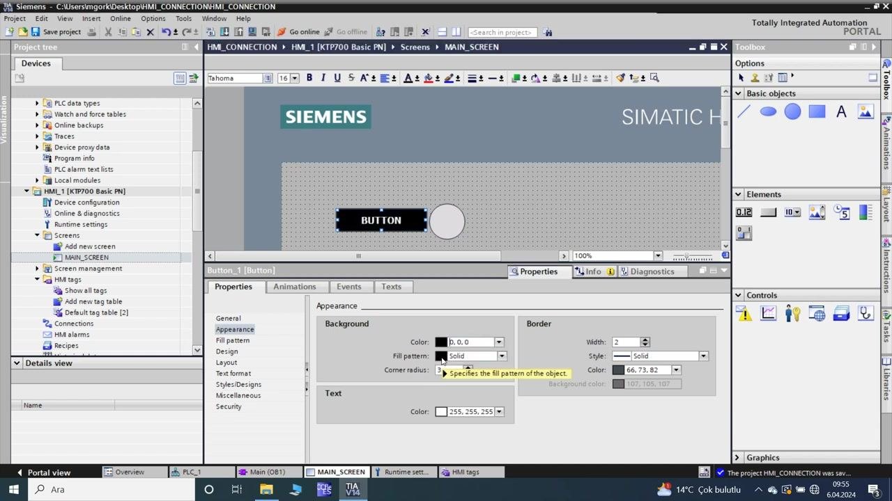
- Select the rectangular button labeled "BUTTON".
- In the "Properties" pane, under the "Appearance" tab:
- Set the background color to black (
0,0,0). - Set the fill pattern to "Solid".
- Set the border width to
2, style to "Solid", and color to66,73,82. - Set the text color to white (
255,255,255).
- Set the background color to black (
- A tooltip is visible: "Specifies the fill pattern of the object".
- The button text is bold and centered.
-
Adjust the button layout
- With the button still selected, switch to the "Layout" tab in the "Properties" pane.
- Set the position and size:
- X:
93, Y:79 - Width:
158, Height:41
- X:
- Ensure "Fit object to contents" is unchecked.
- Set all text and picture margins to
0. - Set the alignment graphic to "Centered" (horizontal) and "Middle" (vertical).
-
Format the button text
- Switch to the "Text format" tab in the "Properties" pane.
- Set the font to
Tahoma, 15px, style=Bold. - Set orientation to "Horizontal".
- Set alignment to "Centered" (horizontal) and "Middle" (vertical).
-
Configure the circle animation tag
- Select the circular object next to the button.
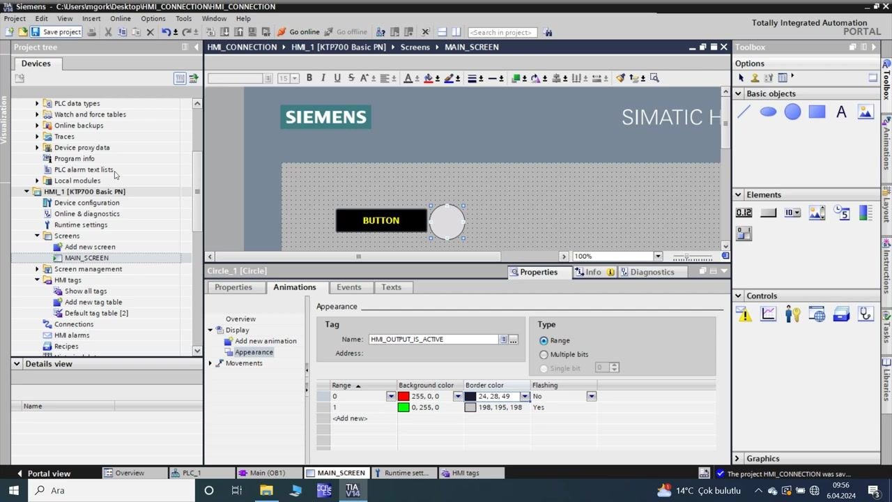
- In the "Properties" pane, switch to the "Animations" tab, then select "Appearance".
- Assign the tag
HM_OUTPUT_I5_ACTIVEto the circle. - Set the type to "Range".
- Add two ranges:
- Range 0: Background color
222,219,222, Border color24,28,49, Flashing "No". - Range 1: Background color
222,219,222, Border color24,28,49, Flashing "No".
- Range 0: Background color
-
Set the circle animation colors
- Update the ranges for the circle's appearance:
- Range 0: Background color
255,0,0(red), Border color24,28,49, Flashing "No". - Range 1: Background color
255,0,0(red), Border color24,28,49, Flashing "No".
- Range 0: Background color
- Add a new range (Range 2): Background color
0,255,0(green), Border color198,195,198, Flashing "Yes".
- Update the ranges for the circle's appearance:
-
Finalize the circle animation settings
- Ensure the final configuration for the circle's animation is:
- Range 0: Background color
255,0,0(red), Border color24,28,49, Flashing "No". - Range 1: Background color
0,255,0(green), Border color198,195,198, Flashing "Yes".
- Range 0: Background color
- The tag remains
HM_OUTPUT_I5_ACTIVE, type "Range", with the correct colors and flashing settings applied.
- Ensure the final configuration for the circle's animation is:
- Start the HMI simulation
- Initiate the simulation process for the HMI screen.
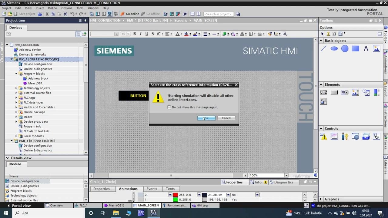
- A warning dialog appears: "Starting simulation will disable all other online interfaces."
- Click OK to proceed.
- Wait for the simulation to start
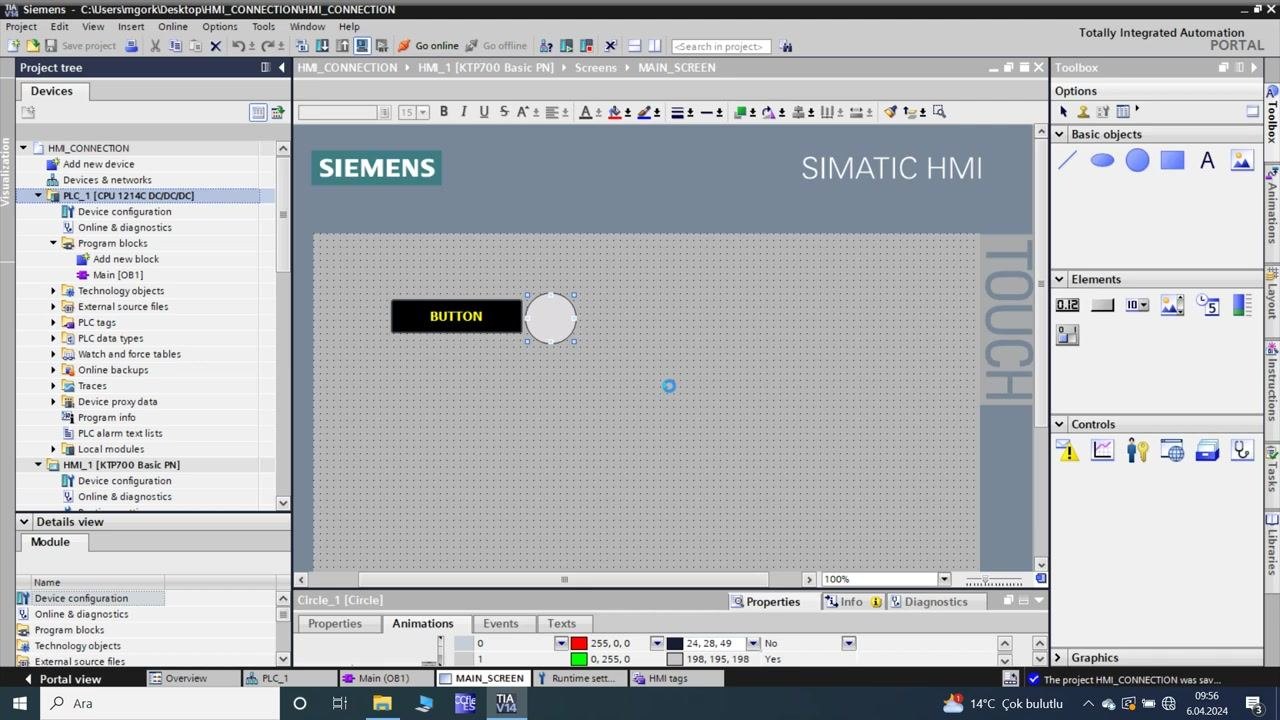
- The simulation process begins, indicated by a loading spinner on the HMI screen.
- The screen remains unchanged except for the spinner, confirming the simulation is initializing.
Section 6: Download, test, and verify the HMI-PLC connection
- Scan and select the target device for download
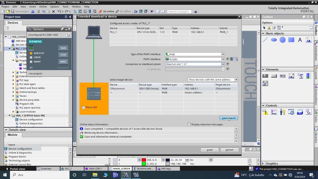
- In the "Extended download to device" window, confirm that the scan for accessible devices is complete.
- Ensure the following details are visible:
- Device:
PLC_1 - Device type:
CPU 1214C DC/DC/DC - Address:
192.168.0.1 - Interface:
PNIE - PG/PC interface:
PLCSIM
- Device:
- Under "Select target device," verify that
CPUcommonis listed with the correct address. - Click Start search to confirm device accessibility.
- Check before loading
- In the "Load preview" window, review the checklist before downloading:
- Status for
PLC_1should be "Ready for loading." - Simulated module: "The download will be performed to a simulated PLC."
- Device configuration: "Delete and replace system data in target."
- Software: "Download software to device."
- Text libraries: "Download all alarm texts and text list texts."
- Status for
- Click Load to proceed with downloading the configuration to the simulated PLC.
- In the "Load preview" window, review the checklist before downloading:
-
Wait for the configuration to load
- Observe the "Download to device" dialog indicating "Loading configuration. This will take some time."
- Wait for the loading process to complete.
- You may cancel if necessary, but allow the process to finish for successful deployment.
-
Monitor the PLC program in TIA Portal
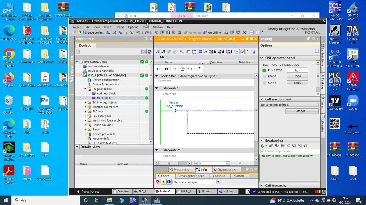
- Once loading is complete, the TIA Portal main window displays the PLC program block (
Main [OB1]). - The project tree on the left shows the device structure, and the ladder logic is visible in the main workspace.
- The CPU operator panel on the right indicates the PLC is in RUN mode.
- The ladder logic includes:
%M0.0("HMI_BUTTON") controlling%Q0.0("OUTPUT") and%M0.1("HM_OUTPUT_I5_ACTIVE").
- No errors or warnings are present.
- Once loading is complete, the TIA Portal main window displays the PLC program block (
-
Review the ladder logic for HMI interaction
- The ladder diagram in the "Main Program Sweep (Cycle)" block shows:
- Network 1:
%M0.0("HMI_BUTTON") as the input, controlling%Q0.0("OUTPUT") and%M0.1("HM_OUTPUT_I5_ACTIVE") as outputs.
- Network 1:
- This logic ensures that pressing the HMI button activates both the output and the animated indicator tag.
- The ladder diagram in the "Main Program Sweep (Cycle)" block shows:
-
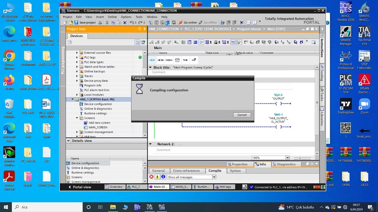
Compile the configuration
- A "Compiling configuration" dialog appears, indicating the system is compiling the latest changes.
- Wait for the compilation to finish before proceeding.
-
Verify successful compilation
- After compilation, the TIA Portal window returns to the main view.
- The project tree and ladder logic remain visible, confirming the configuration is ready for runtime testing.
-
Test the HMI and PLC logic in the Runtime Simulator
- Open the "RT Simulator" window to view the HMI screen.
- The HMI screen displays:
- "SIEMENS" logo, "SIMATIC HMI" label, and "TOUCH" branding.
- The rectangular "BUTTON" (black background, yellow text) and the circular indicator (initially green outline).
- Function keys F1–F8 at the bottom.
- The mouse cursor is positioned over the "BUTTON," indicating a test click is about to occur.
- The TIA Portal window remains open in the background, showing the ladder logic in real time.
-
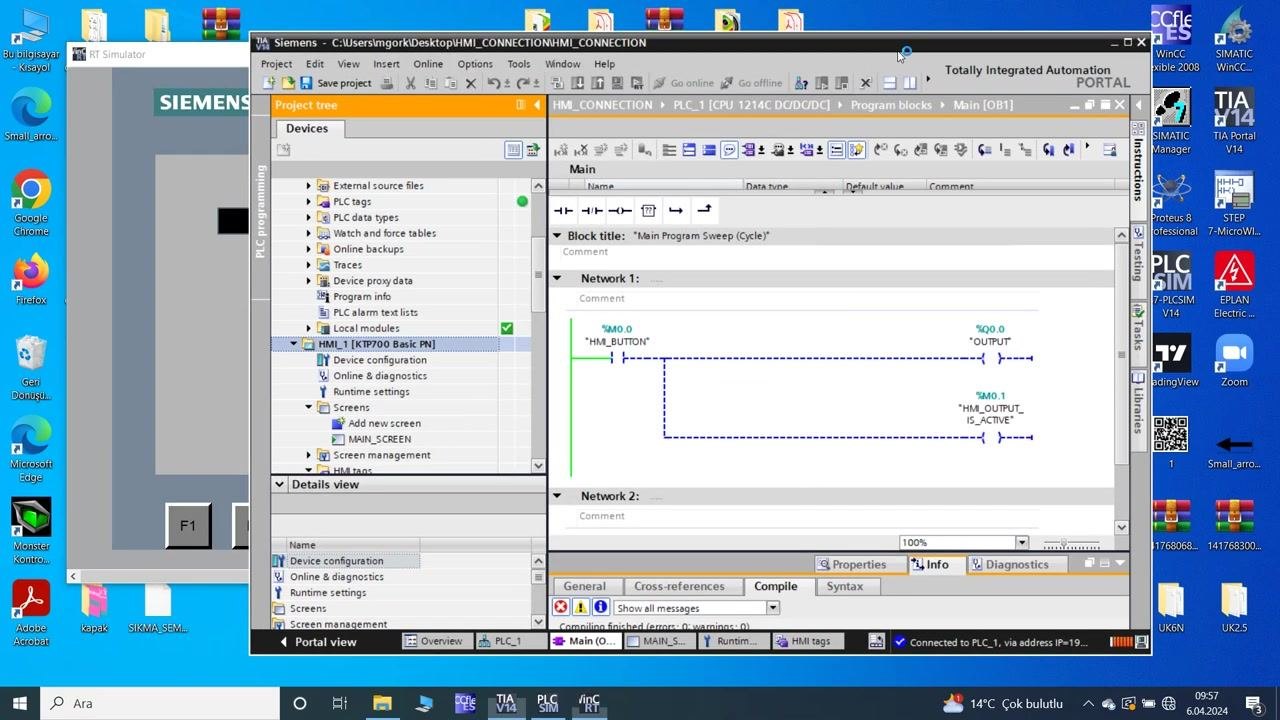
Observe the indicator animation on button press
- After pressing the "BUTTON" on the HMI screen:
- The circular indicator changes to a solid red color, reflecting the logic in the PLC program and the animation settings configured earlier.
- The ladder logic in TIA Portal shows the rung is active (green lines), confirming the tag
%M0.1("HM_OUTPUT_I5_ACTIVE") is set.
- This verifies that the HMI button correctly triggers the PLC logic and updates the animated indicator as intended.
- After pressing the "BUTTON" on the HMI screen:
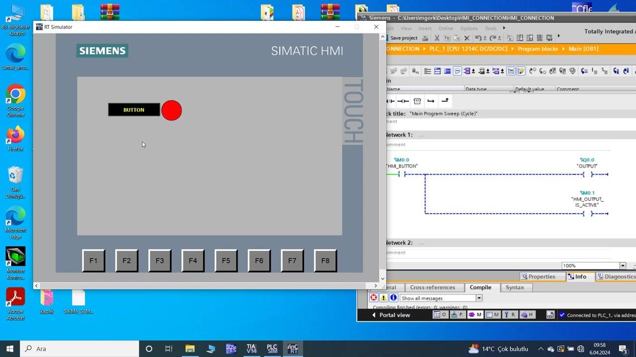
- Confirm the persistent indicator state
- The HMI screen continues to display the red indicator, confirming the state is maintained as long as the button logic remains active.
- The TIA Portal ladder logic remains highlighted, showing the output and indicator tags are still set.
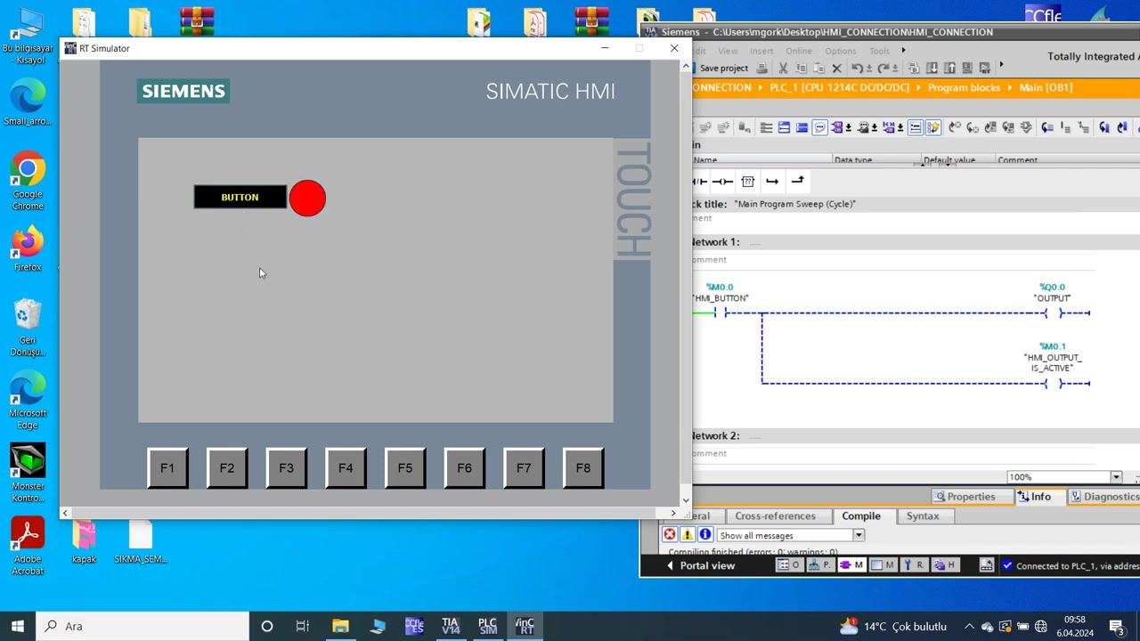
- Perform final verification of the HMI-PLC integration and system state
- Observe the desktop environment, which displays both the HMI Runtime Simulator and the TIA Portal software side by side.
- In the RT Simulator window (HMI screen):
- The "SIEMENS" logo is visible in the upper left.
- The "SIMATIC HMI" label and "TOUCH" branding are present on the right.
- The main HMI area shows:
- A rectangular button labeled "BUTTON" (black background, yellow text).
- A circular indicator next to the button, which is solid red, confirming the indicator is active.
- Function keys F1–F8 are displayed at the bottom of the HMI screen.
- The mouse cursor is visible, indicating the system is ready for further interaction.
- In the TIA Portal window (partially visible on the right):
- The "Main Program Sweep (Cycle)" block is open, showing the ladder logic for the PLC.
- Network 1 is displayed, with the following logic:
%M0.0("HMI_BUTTON") as the input.%Q0.0("OUTPUT") and%M0.1("HM_OUTPUT_IS_ACTIVE") as outputs.
- The rung is highlighted, indicating the logic is currently active.
- The status bar at the bottom confirms the PLC is connected and running without errors.
- The Windows desktop background and several application shortcuts are visible, but no other actions are being performed.
Verification and summary
This state confirms the following:
- The HMI button press correctly triggers the PLC logic.
- The animated indicator on the HMI reflects the PLC output state.
- The system is stable and ready for further testing or operation.
You have completed the end-to-end process of configuring, downloading, and verifying the HMI-PLC integration in TIA Portal. The button uses bold, centered text, and the indicator circle changes color and flashes based on the value of the assigned tag. The final system state confirms that the HMI button successfully activates the PLC logic and updates the animated indicator, demonstrating correct communication and animation behavior between the HMI and PLC simulation environments. The system is now ready for additional testing, deployment, or further development as needed.
Generation details: cost, quality tiers
Docsie billed 4,500 credits ($3.15) to analyze this 9-minute video at standard quality. The rewrite, template fill and Word/PDF exports were included. The same video at each quality tier:
| Quality | Frames sampled | Credits | Approx. cost |
|---|---|---|---|
| Draft | every 16-30 s | 2,250 | $1.57 |
| Standard (this guide) | every 8-15 s | 4,500 | $3.15 |
| Detailed | every 4-7 s | 9,000 | $6.30 |
| Ultra | every 1-3 s | 18,000 | $12.60 |
Credits priced at $0.70 per 1,000; plans include a monthly allowance. Enterprise customers on on-premise or bring-your-own-model deployments run this on their own inference and pay no per-video credits.
Generated by Docsie Video-to-Docs on 2026-09-14 from a 8-minute video. Screenshots are frames from the source video and belong to their creator, TechJourneyHub, whose original is embedded above. If you own this video and want the guide removed or credited differently, contact us and we will act within one business day.