
How to Test a Relay with a Multimeter
This procedure explains how to test a relay with a multimeter by identifying its terminals, understanding its circuit operation, and verifying the switch state both with and without voltage applied to the coil. Follow these steps to confirm whether a relay is functioning correctly before installing or replacing it.
Video: Learn how to test Relays with multimeter, how relay works by Electronics Repair Basics_ERB (2022). All credit for the demonstration goes to the creator; watch the original on YouTube. The written guide below was generated from this video by Docsie. Creator? Request a change or removal.
This procedure explains how to test a relay with a multimeter by identifying its terminals, understanding its circuit operation, and verifying the switch state both with and without voltage applied to the coil. Follow these steps to confirm whether a relay is functioning correctly before installing or replacing it.
Purpose
This SOP guides you through inspecting a relay's terminals, reading its technical specifications, and using a multimeter to confirm that the internal switch opens and closes correctly when the coil is energized.
Scope
This procedure applies to standard four-terminal relays, such as the SANYOU SRU-S-112L type shown in this guide, where two terminals belong to the inductor (coil) and two belong to the switch (contacts).
Required equipment
- A relay to be tested (four-terminal type)
- A digital multimeter (e.g., CHY DT-9205L or IDEAL 61-327) set to resistance/continuity mode
- A DC power adapter matching the relay's coil voltage (e.g., a 12V DC adapter such as the HUAWEI HW-120100E01)
- Connecting wires
- A flat, non-conductive work surface
Part 1: Identifying relay terminals and understanding operation
Step 1: Identify the relay terminals
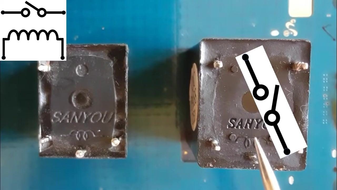
Observe the relay component and note that it contains four terminals: two for the inductor (coil) and two for the switch (contacts). Examine the relay body for markings that help identify each terminal, and ignore any additional terminals that are not used.
Step 2: Locate the inductor terminals
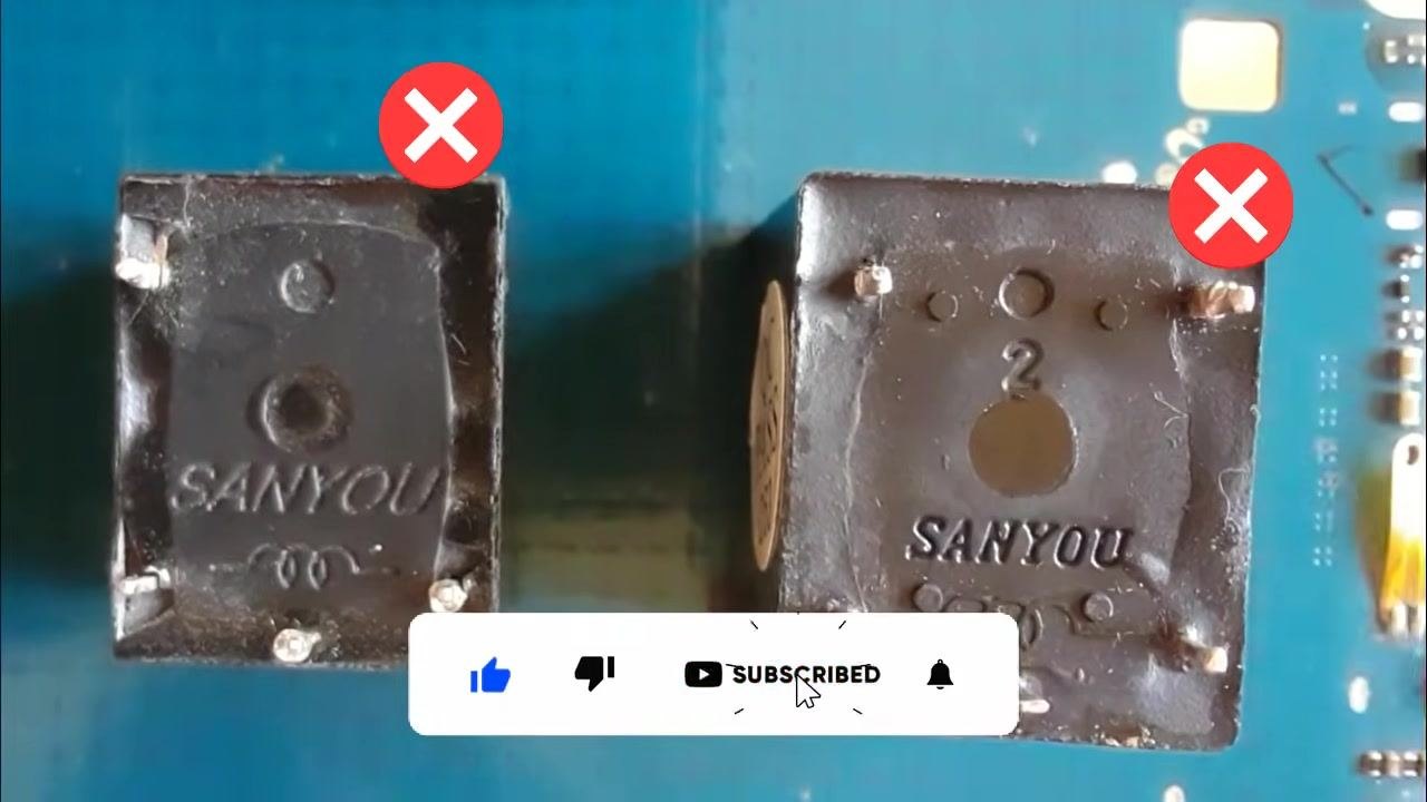
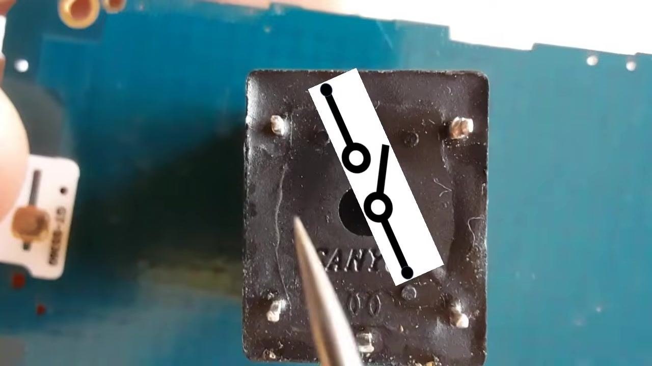
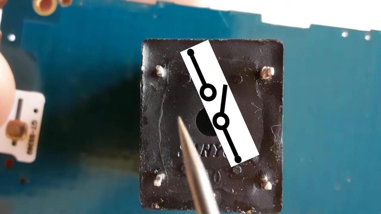
Identify the two terminals connected to the coil. These are typically positioned opposite each other on the relay body. A red X marks any terminal that is not used for this connection.
Step 3: Locate the switch terminals
Identify the two terminals connected to the switch contacts. Ignore any terminal marked with a red X, as it is not part of the switch circuit.
Step 4: Review the relay circuit diagram
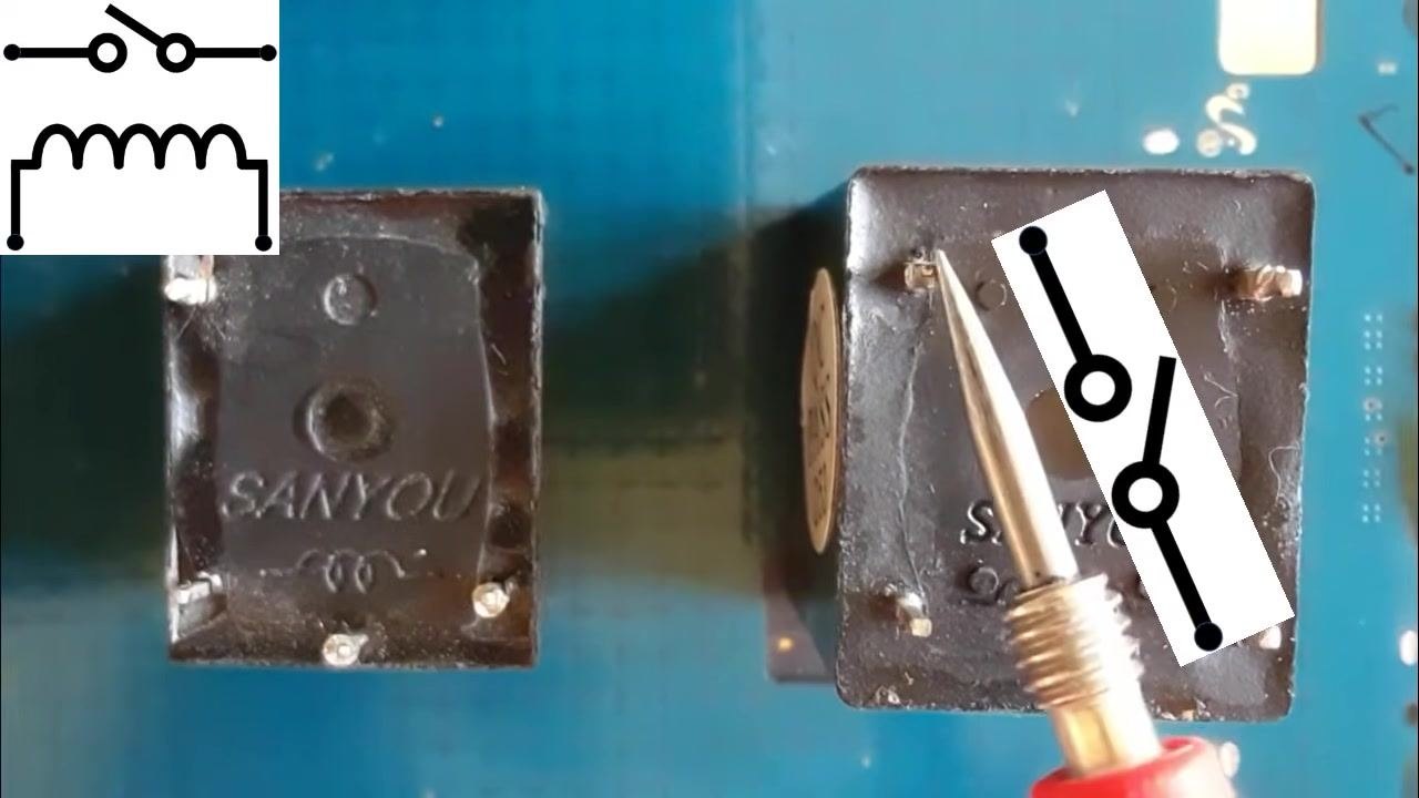
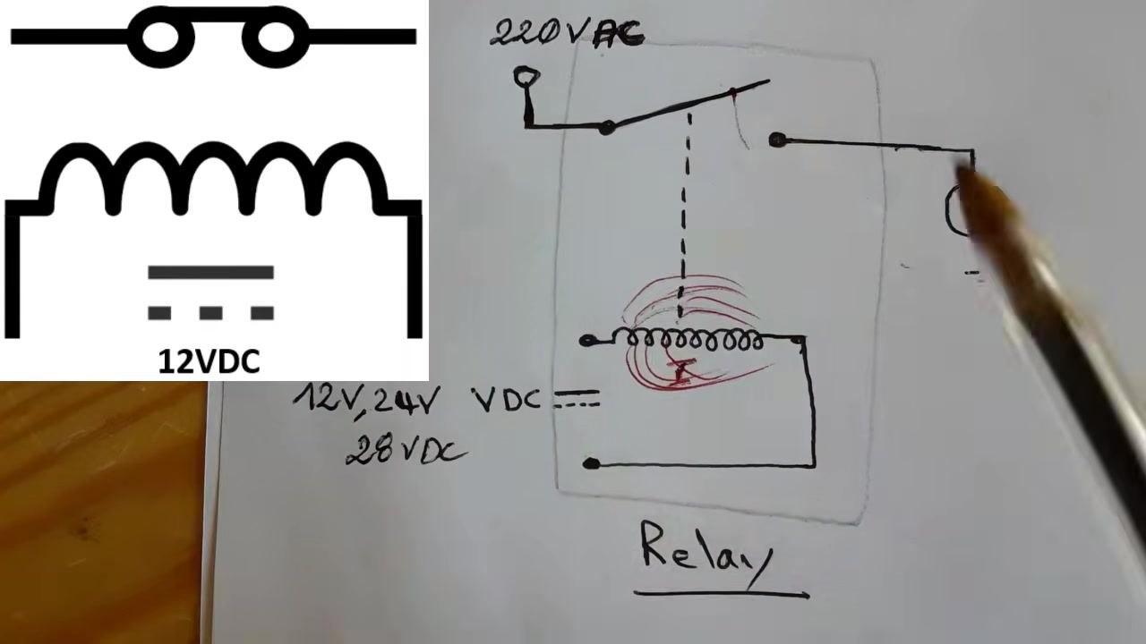
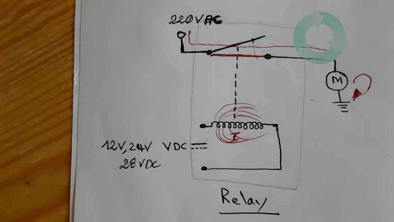
Refer to the relay's basic circuit diagram to identify the inductor and its two terminals, the switch and its two terminals, and the input voltage for the coil (12V, 24V, or 28V DC depending on the relay type). When voltage is applied to the inductor, current flows through it and creates an electromagnetic field.
Step 5: Match the switch terminals to the diagram
Compare the physical switch terminals on the relay to their representation in the circuit diagram to confirm your understanding of the layout.
Step 6: Confirm the coil's input voltage type
Check the circuit diagram for the possible coil input voltages: 12V DC, 24V DC, or 28V DC. Always use the voltage specified for your relay model.
Step 7: Understand the relay's operating principle
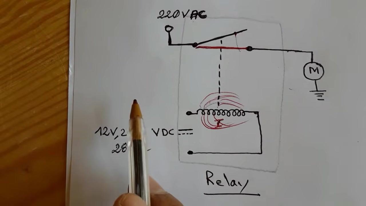
When the specified voltage is applied to the coil terminals, an electromagnetic field is generated. This field pulls the pole and closes the switch, allowing main power to pass through to the load, such as a motor.
Step 8: Observe the switching action in the circuit
When the coil is energized, the pole is pulled and the switch closes, allowing main power to flow through the switch to the load and causing it to operate.
Step 9: Visualize the load activation example
In this example, a motor serves as the load. When the relay switch closes, the circuit is completed and the motor runs.
Step 10: Review the relay's technical characteristics
Examine the markings on the relay body to identify the manufacturer (SANYOU), model number (SRU-S-112L), switch voltage/current ratings (10A 240V AC, 10A 24V DC, 15A 120V AC), and coil working voltage (12V, 24V, or 28V DC). If a relay is damaged, replace it only with another relay of the same reference/model.
Step 11: Confirm the relay reference and ratings
Double-check the model number (SRU-S-112L) and verify the printed voltage and current ratings before selecting a replacement relay.
Step 12: Identify certification marks and additional ratings
Locate certification marks, such as CQC, and confirm any additional ratings printed on the relay, such as 10A at 250V AC.
Step 13: Identify the coil's working voltage
Find the rated working voltage for the coil. In this example, the relay is rated for 10A at 24V DC.
Step 14: Prepare the power adapter for testing
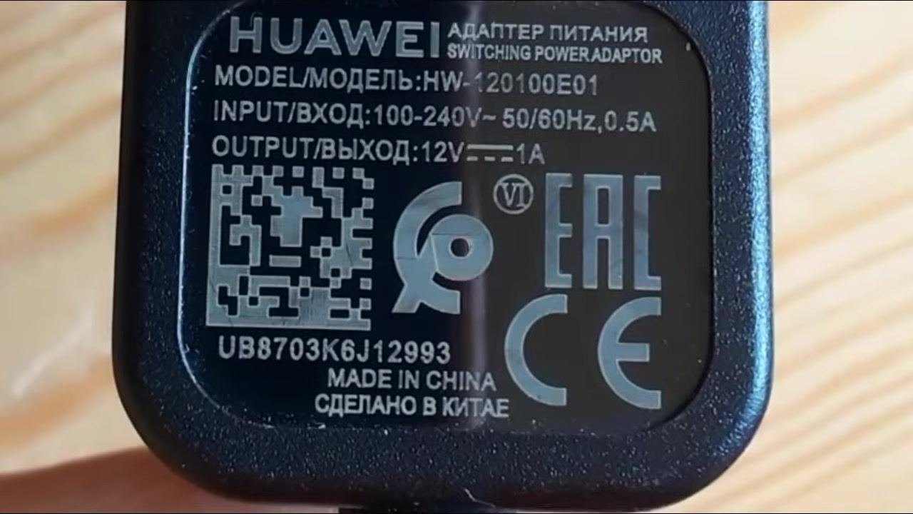
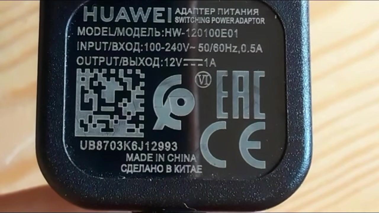
Obtain a DC adapter matching the relay's coil voltage. Confirm the adapter's specifications, including brand, model, input rating, and output rating, before use.
Step 15: Verify the adapter's output specifications
Double-check that the adapter's output voltage and current match the relay's coil requirement. In this example, the output is 12V DC, 1A.
Step 16: Identify the coil and switch terminals for testing
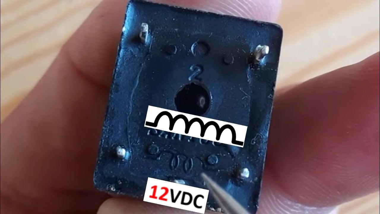
Turn the relay over to view the bottom terminals. Locate the coil symbol and the "12VDC" marking, then identify the correct terminals for connecting the adapter.
Part 2: Testing the relay switch with a multimeter
Step 17: Set up the relay for baseline testing
Place the relay on a flat, non-conductive surface with the terminals facing up. Ensure the relay is not energized, meaning no voltage is applied to the coil, before connecting the multimeter.
Step 18: Measure the switch state with no voltage applied
Set the multimeter to resistance or continuity mode and touch the probes to the relay's switch terminals. Confirm that the display shows "1" or "OL" (over limit), indicating an open circuit.
Step 19: Energize the relay coil
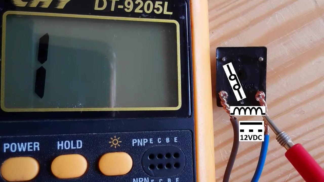
Apply 12V DC to the coil terminals using the prepared adapter. Ensure correct polarity and secure connections; the relay switch should now close.
Step 20: Check switch continuity while energized
With 12V DC still applied to the coil, use the multimeter to measure resistance across the switch terminals.
Step 21: Confirm low resistance indicates a closed switch
Read the multimeter display; a value close to 0 ohms (e.g., 0.04 Ω) confirms the switch is closed and the relay is functioning correctly.
Step 22: Remove power and confirm the switch reopens
Disconnect one terminal of the 12V DC supply from the coil. Confirm the coil is now at 0V DC, then check the switch terminals again with the multimeter.
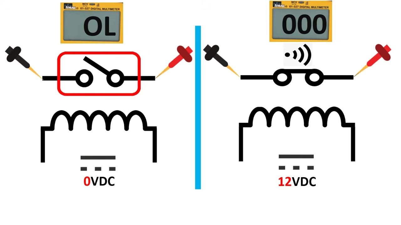
Step 23: Review the summary of relay states
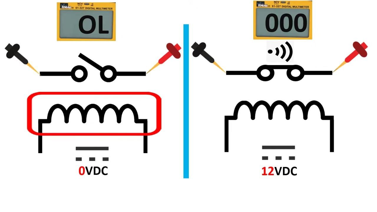
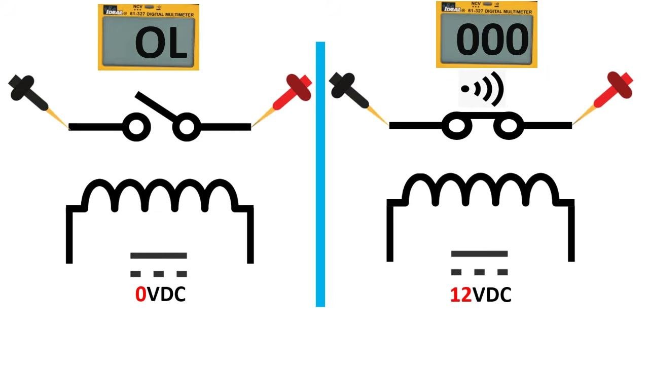
Compare the two relay states side by side: with no voltage on the coil (0VDC), the switch is open and the multimeter reads "OL"; with 12VDC applied, the switch is closed and the multimeter reads "000".
Step 24: Confirm the default switch position
By default, with no voltage applied to the coil, the switch remains open. This is illustrated in the schematic with the inductor highlighted in the de-energized state.
Step 25: Set up a second verification test
Review the test setup diagram again: with 0VDC on the coil, the multimeter reads "OL" (open); with 12VDC applied, it reads "000" (closed, continuity).
Step 26: Connect the multimeter probes to the switch terminals
Attach the black and red probes to the two switch terminals. Ensure the relay is not energized; the multimeter should display "OL," confirming the switch is open.
Step 27: Apply 12VDC to the relay coil
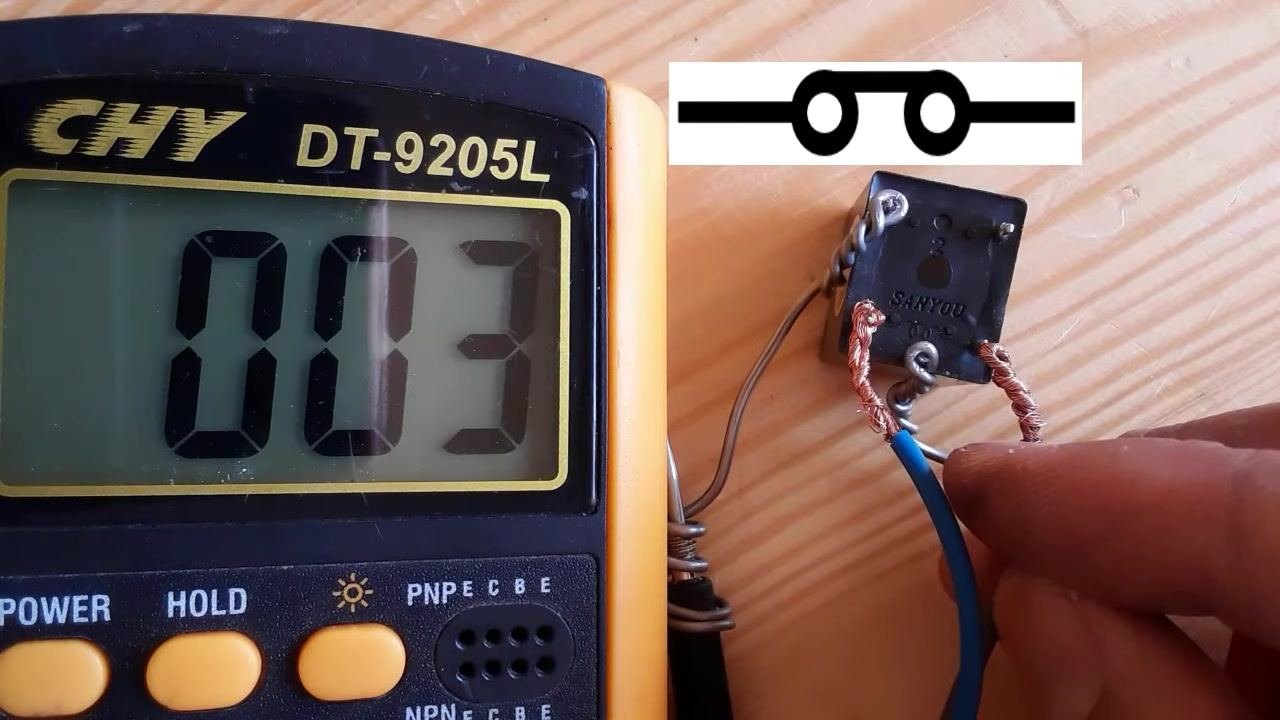
Use a test probe or power supply to apply 12VDC to the coil terminals. The schematic overlay confirms the coil is now energized, and the relay switch should close.
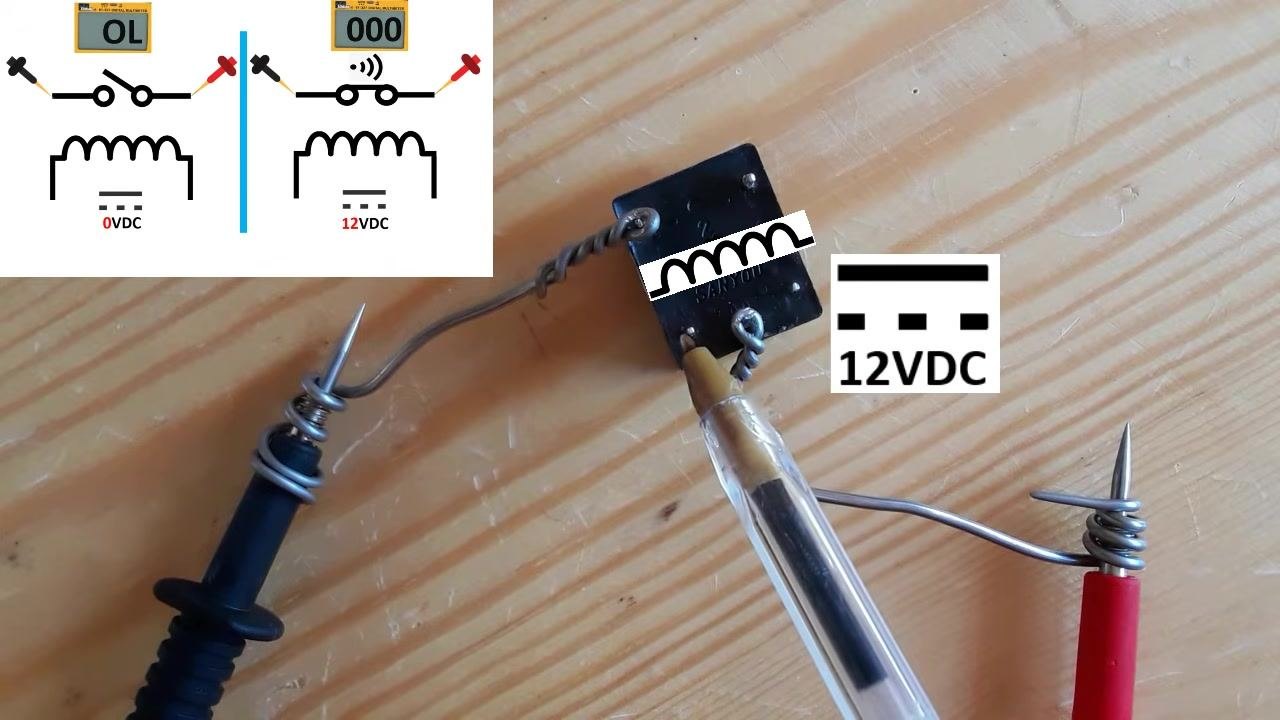
Step 28: Observe the multimeter reading with the coil energized
With 12VDC applied, the switch closes and the multimeter displays a low resistance value (e.g., "034"), indicating continuity. Listen for a click from the relay, which confirms the switch has actuated.
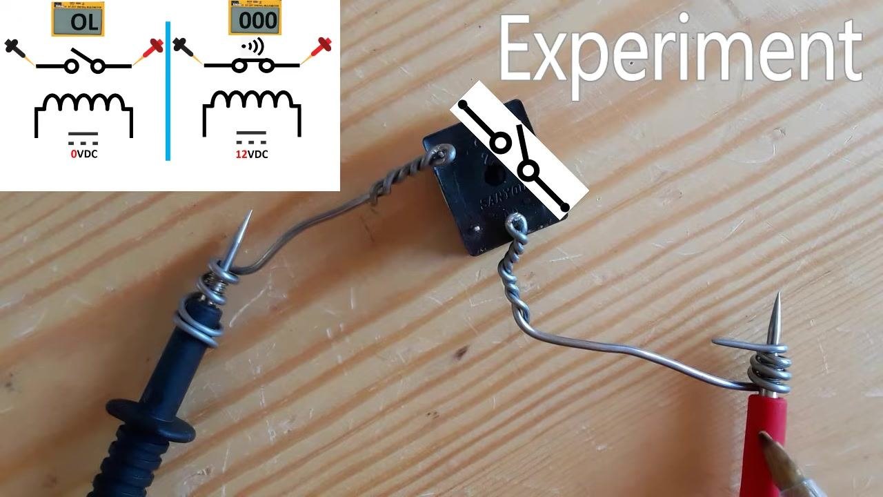
Step 29: Test the switch by removing and reapplying voltage
Remove and reapply voltage to the coil to observe the switch opening and closing. An open switch shows a higher resistance reading (e.g., "562"), while a closed switch shows a very low resistance (e.g., "003"). The schematic overlay updates to reflect the current switch state.
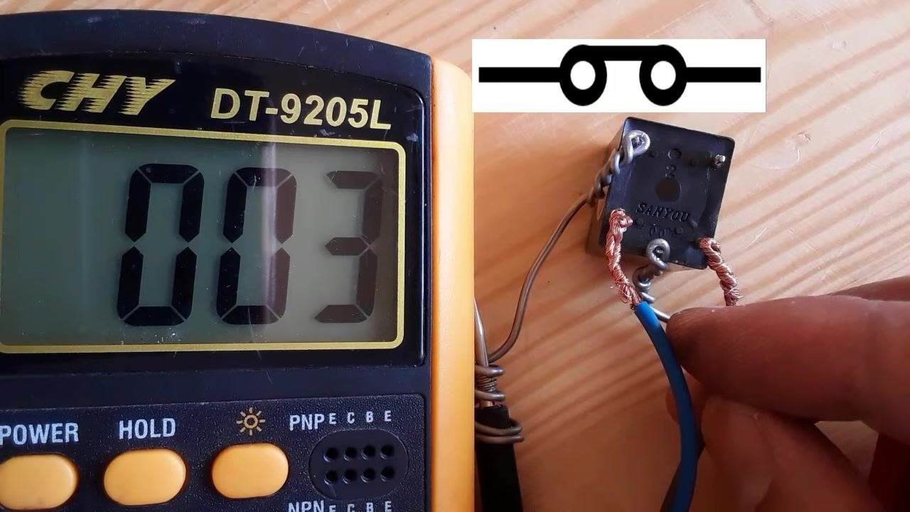
Step 30: Verify the final reading with the relay energized
Confirm the multimeter still shows a low reading (e.g., "003") while the coil remains energized, with the schematic symbol showing the switch closed. Ensure the probes remain securely connected to the switch terminals throughout the check.
Step 31: Disconnect the test setup
Turn off or disconnect the voltage supply to the relay coil, then remove the multimeter probes from the switch terminals. Safely disconnect all wiring from the relay and multimeter, and store the equipment for future use.
Verification and summary
A properly functioning relay shows the following behavior when tested with a multimeter:
- With no voltage applied to the coil, the switch is open and the multimeter reads "1" or "OL" (open circuit).
- With the rated voltage (e.g., 12V DC) applied to the coil, the switch closes and the multimeter reads a low resistance value close to 0 ohms, confirming continuity.
- Removing power from the coil returns the switch to its open state, and the multimeter reading returns to "1" or "OL."
If the relay does not switch between these two states as expected, replace it with another relay of the same reference/model to ensure proper voltage and current compatibility.
Generation details: cost, quality tiers
Docsie billed 3,500 credits ($2.45) to analyze this 7-minute video at standard quality. The rewrite, template fill and Word/PDF exports were included. The same video at each quality tier:
| Quality | Frames sampled | Credits | Approx. cost |
|---|---|---|---|
| Draft | every 16-30 s | 1,750 | $1.22 |
| Standard (this guide) | every 8-15 s | 3,500 | $2.45 |
| Detailed | every 4-7 s | 7,000 | $4.90 |
| Ultra | every 1-3 s | 14,000 | $9.80 |
Credits priced at $0.70 per 1,000; plans include a monthly allowance. Enterprise customers on on-premise or bring-your-own-model deployments run this on their own inference and pay no per-video credits.
Generated by Docsie Video-to-Docs on 2026-09-14 from a 6-minute video. Screenshots are frames from the source video and belong to their creator, Electronics Repair Basics_ERB, whose original is embedded above. If you own this video and want the guide removed or credited differently, contact us and we will act within one business day.