
How to Tell If a Circuit Breaker Is Bad
Knowing how to tell if a circuit breaker is bad protects your wiring, your equipment, and the people who rely on your electrical system. A breaker that fails to trip when it should — or trips when it shouldn't — can allow dangerous overheating or leave circuits unpowered without warning. This procedure walks through the visual inspection, mechanical checks, and electrical tests you can use to confirm whether a breaker is functioning correctly or needs to be replaced.
Video: How to Tell if a Breaker is Bad by Electrician U (2021). All credit for the demonstration goes to the creator; watch the original on YouTube. The written guide below was generated from this video by Docsie. Creator? Request a change or removal.
Knowing how to tell if a circuit breaker is bad protects your wiring, your equipment, and the people who rely on your electrical system. A breaker that fails to trip when it should — or trips when it shouldn't — can allow dangerous overheating or leave circuits unpowered without warning. This procedure walks through the visual inspection, mechanical checks, and electrical tests you can use to confirm whether a breaker is functioning correctly or needs to be replaced.

Purpose
This procedure explains how to determine whether a circuit breaker is good or bad by testing its trip response, inspecting it for mechanical and physical damage, and measuring voltage at its terminals. It also covers how to source replacement breakers for legacy panels and how to verify specialty breakers, such as smart breakers and dual-function (AFCI/GFCI) breakers.
Scope
This procedure applies to residential and commercial breaker panels and covers:
- Understanding breaker trip thresholds for overload, short-circuit, and ground-fault conditions
- Visual and mechanical inspection of breakers for signs of failure
- Multimeter-based voltage testing at breaker terminals
- Sourcing replacement breakers for obsolete or legacy panels
- Testing smart breakers, shunt trip breakers, and dual-function breakers
Required equipment
- A multimeter for voltage testing
- A clamp meter, where applicable, for current readings
- Replacement breakers matched to the panel brand and amperage
- Basic hand tools to remove a breaker from its panel slot
- Access to a specialty parts supplier or retailer for legacy breaker brands
Procedure
Step 1: Understand breaker current ratings and trip thresholds
A breaker is designed to hold its rated current continuously — for example, a 20 amp breaker should hold at 20 amps without tripping. When current exceeds the rated value, the breaker is supposed to trip to protect the circuit. This tripping mechanism protects the insulation around the conductor from overheating and melting, even when there is no short circuit or ground fault present.

Step 2: Recognize the danger of an overheating breaker
A thermal overload trip typically occurs at about 130% of the breaker's rated value. For a 20 amp breaker, this means it should trip at approximately 26 amps, though the trip may not be immediate — it can take time for the breaker to respond to an overload. If a breaker does not trip at the appropriate overload value, it may be faulty, and visible damage such as melted insulation is a clear sign that overheating has already occurred.

Step 3: Distinguish overload, short-circuit, and ground-fault trip levels
Short circuits and ground faults are treated at a higher threshold than ordinary overloads — around 200% of the breaker's rated value. For a 20 amp breaker, this equals roughly 40 amps. At these higher current levels, the breaker must trip immediately to prevent severe damage. Note that field electricians cannot easily simulate 130% or 200% loads, but real-world overloads and faults can still reveal a breaker that fails to trip as expected.
Step 4: Identify the short-circuit trip threshold
Short-circuit conditions require the breaker to trip at approximately 200% of its rated value to prevent damage to wiring and equipment.
Step 5: Identify the ground-fault trip threshold
Ground-fault conditions carry the same 200% trip threshold as short circuits. A breaker that fails to trip immediately under either condition should be considered suspect.
Step 6: Recognize mechanical failure symptoms
If a breaker does not trip when expected, there may be a mechanical issue inside. Watch for these signs of a bad breaker:
- The breaker will not reset (cannot be switched to the ON position)
- The breaker trips immediately after being reset, even with no load connected
- The handle feels "mushy" or lacks mechanical resistance compared to other breakers
- The handle does not move even though the internal mechanism has tripped
Some brands, such as GE, are noted for this type of mechanical failure.
Step 7: Test for mechanical issues by resetting the breaker
Attempt to reset the breaker by flipping it to the ON position and observe whether it stays on or trips immediately. Compare the feel of the handle to other breakers in the panel — a weak or mushy handle indicates a problem. If the breaker fails these tests, it is likely faulty and should be replaced.
Step 8: Watch for older breakers that appear "on" but are not conducting
Some older, narrow-profile GE breakers may appear to be in the ON position while the circuit is actually off. If a customer reports that all breakers are switched ON yet power is not restored, this false-position issue should be suspected and checked directly.
Step 9: Test breaker handles for weak springs
Gently tap each breaker handle toward the OFF position using your finger, without applying excessive force, so you do not accidentally switch a good breaker off. If a handle suddenly flips to OFF after tapping, this indicates the internal mechanism was already tripped even though the handle had not moved. Reset the breaker by flipping it back to ON and check whether power is restored. This is a common issue with older GE breakers and points to a problem with the handle mechanism, even when the internal breaker function is otherwise intact. Replace any breaker that shows this symptom.
Step 10: Inspect for physical damage to breaker handles
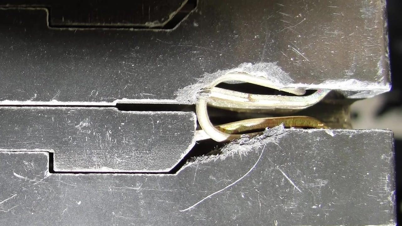
Look for broken or busted breaker handles. If a handle is damaged, the breaker cannot be reliably switched ON or OFF and must be replaced. Do not leave a breaker with a damaged handle installed in the panel.
Step 11: Examine the breaker terminal for arcing or overheating
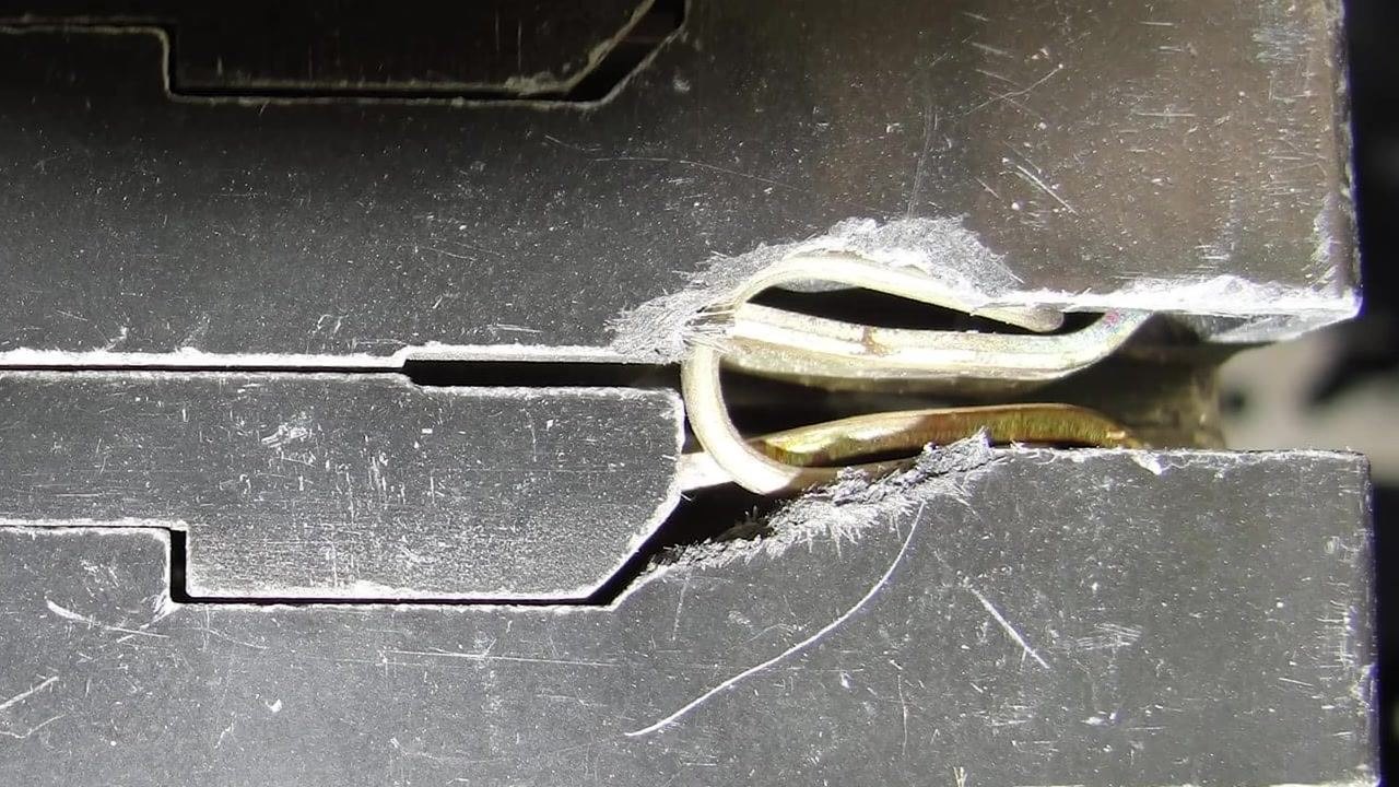
Remove the breaker from the panel and inspect the back and case for any signs of melting, charring, or discoloration. Check the terminal where the branch circuit conductor connects for evidence of arcing or overheating. Replace the breaker immediately if you observe any melting, charring, or arcing at the contacts or terminals.
Step 12: Recognize additional signs of internal damage
Replace the breaker if you notice any of the following:
- The handle does not move, or feels loose or mushy
- The breaker trips immediately after being reset, even with no load
- There is visible damage, melting, or arcing on the breaker body or terminals
Step 13: Document and replace faulty breakers
Record the location and type of any breaker found to be faulty. Replace all breakers that fail mechanical or visual inspection to ensure electrical safety and reliability.

Step 14: Determine whether overheating originates in the circuit or the breaker
Excess heating in a breaker can be caused by issues in the connected circuitry or by mechanical problems within the breaker itself. Overheating is often triggered by something occurring within the circuit, which then causes the breaker to overheat internally. When diagnosing overheating, check both the wiring and circuit and the breaker itself.
Step 15: Source replacement breakers for legacy panels
Identify replacement breakers for old or obsolete panel brands, including Connecticut Electric, Federal Pacific, Zinsco, Pushmatic, Wadsworth, and Challenger. These replacement breakers are essential for maintaining legacy electrical systems where the original manufacturer may no longer be in business.
Step 16: Find specialty suppliers for uncommon breaker brands
Some breaker brands are less common and may require specialty suppliers rather than standard retail outlets. Brands such as Federal Pacific, Zinsco, and Pushmatic often fall into this category, so identify a supplier that stocks the specific legacy breaker you need before starting the replacement.
Step 17: Visit an online specialty supplier for legacy breakers
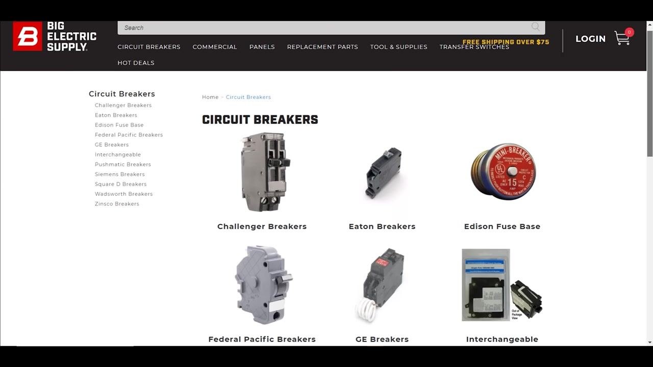
Online suppliers such as Big Electric Supply offer a wide range of circuit breakers, including Challenger, Eaton, Edison Fuse Base, Federal Pacific, GE, Interchangeable, Pushmatic, Siemens, Square D, Wadsworth, and Zinsco breakers. Use the website's navigation to select the breaker type you need.
Step 18: Browse the catalog for your specific breaker brand
The supplier's catalog displays images and categories for each breaker type, making it easy to identify and select the correct replacement. Scroll through the options to find brands such as Pushmatic, Siemens, and Square D.
Step 19: Check for shipping offers and category navigation
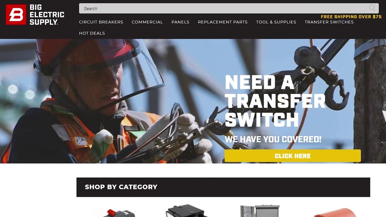
The supplier's homepage features a banner for transfer switches and a Shop by Category section for easy navigation, along with an offer of free shipping on orders over $75. Common sources for legacy breakers also include retailers such as Home Depot in addition to dedicated online suppliers.
Step 20: Learn about specialty smart breakers
Specialty breakers may include advanced features not found in standard models. Smart breakers, for example, are typically remotely controlled and may include labels such as "Remotely Operated" and AUTO/MAN switches, along with trip indicators and digital displays.
Step 21: Understand shunt trip breaker function
Shunt trip breakers are standard breakers with an additional circuit, often 110V but variable, that allows them to be tripped remotely, either by a person or triggered automatically by an event.
Step 22: Troubleshoot a shunt trip breaker that fails to trip
If a shunt trip breaker fails to trip when activated, further investigation is needed to verify breaker operation. Many service calls involve replacing smart breakers that are not functioning as expected, so confirm the breaker's response before ruling out other causes.
Step 23: Watch for dual-function breaker issues in residential panels
Dual-function breakers (AFCI/GFCI) are prone to problems and may require testing or replacement more frequently than standard breakers, particularly in residential settings.
Step 24: Test AFCI, GFCI, or dual-function breaker buttons after installation
Do not assume a new breaker is functional straight from the factory. Press the colored test button (white, purple, or green) on arc-fault, ground-fault, or dual-function breakers to simulate a fault and confirm the breaker trips. Labels on these breakers may include amperage, "10 kA," "120/240V," and COMBINATION AFCI.
Step 25: Verify new breakers by pressing the test button
Always press the test button to simulate a fault, even on a new breaker. Occasionally a breaker may fail to simulate a fault when tested, which indicates a defective unit that should not be left in service.
Step 26: Test breaker terminal voltage with a multimeter
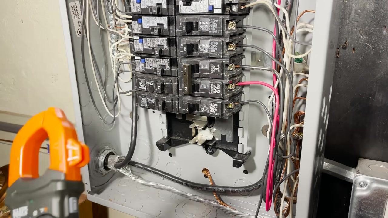
Open the electrical panel to access the breakers and wiring, and identify the terminal where the conductor is connected. Place one probe of the multimeter on the terminal where the conductor is hooked up, and place the other probe on ground or neutral.
Step 27: Interpret the voltage reading for the load type
For a 220V load, expect to see a voltage reading appropriate for the system, such as 220V measured between two hot legs.
Step 28: Investigate unexpected voltage readings
If you measure 120V or another value that does not match what you expect, question why the reading differs from the norm. Take one probe and test between each terminal and ground to further diagnose the issue.
Step 29: Identify a breaker with zero output voltage
If you find zero volts between the breaker terminal and ground or neutral, the breaker is not supplying power. This indicates the breaker is not allowing current to flow, likely due to an internal disconnection or failure.
Step 30: Replace a breaker with no voltage output
A breaker that is not outputting voltage likely needs to be replaced. This issue can occur in both two-pole and three-pole breakers.
Step 31: Check contactors and relays for similar failures
A single failed pole in a contactor or relay can produce the same symptoms as a failed breaker pole, so inspect these components when troubleshooting a no-voltage condition.
Step 32: Address single-phasing risk in three-phase loads
If only one pole fails in a three-phase breaker, the connected load may become single-phased, which can damage equipment. Address this condition promptly by replacing the faulty breaker or component as soon as possible.
Step 33: Consider brand, breaker type, and installation location during troubleshooting
Take into account the brand of the breaker, the specific type of breaker, and the location where it is installed, since these variables can influence the likelihood of issues or failures.
Step 34: Physically remove the breaker for closer inspection if needed
If initial troubleshooting does not reveal the problem and you suspect something unusual, dig deeper into the electrical system. This often involves physically removing the breaker for closer inspection.
Step 35: Inspect the breaker and bus bar for physical damage
Remove the breaker from its slot and examine the bus bar for any signs of damage or wear. Flip the breaker around to inspect all sides for issues before deciding whether it can be reinstalled or must be replaced.
Verification and summary
Before returning a panel to service, confirm the following for every breaker you inspected:
- The breaker holds its rated current and trips at the expected overload, short-circuit, or ground-fault threshold
- The breaker resets cleanly to ON and does not trip immediately with no load connected
- The handle has firm mechanical resistance and is not loose, mushy, or broken
- There is no visible melting, charring, discoloration, or arcing on the breaker body or terminals
- Voltage measured at the terminal matches the expected value for the connected load, with no unexpected zero-volt readings
- Test buttons on AFCI, GFCI, or dual-function breakers trip the breaker as expected
- Replacement breakers for legacy panels are correctly matched to the panel brand and amperage
A breaker that fails any of these checks should be documented and replaced to ensure the electrical system operates safely and reliably.

Generation details: cost, quality tiers
Docsie billed 6,000 credits ($4.20) to analyze this 12-minute video at standard quality. The rewrite, template fill and Word/PDF exports were included. The same video at each quality tier:
| Quality | Frames sampled | Credits | Approx. cost |
|---|---|---|---|
| Draft | every 16-30 s | 3,000 | $2.10 |
| Standard (this guide) | every 8-15 s | 6,000 | $4.20 |
| Detailed | every 4-7 s | 12,000 | $8.40 |
| Ultra | every 1-3 s | 24,000 | $16.80 |
Credits priced at $0.70 per 1,000; plans include a monthly allowance. Enterprise customers on on-premise or bring-your-own-model deployments run this on their own inference and pay no per-video credits.
Generated by Docsie Video-to-Docs on 2026-09-14 from a 11-minute video. Screenshots are frames from the source video and belong to their creator, Electrician U, whose original is embedded above. If you own this video and want the guide removed or credited differently, contact us and we will act within one business day.