
How to Install a Gfci Circuit Breaker
This guide explains how to install a GFCI circuit breaker in an electrical panel, including when this type of breaker is needed, how it differs from a standard breaker, and the wiring steps required to land it safely. Knowing how to install a GFCI circuit breaker correctly protects both equipment and people from ground faults, and in many jurisdictions it also satisfies code requirements for arc fault protection.
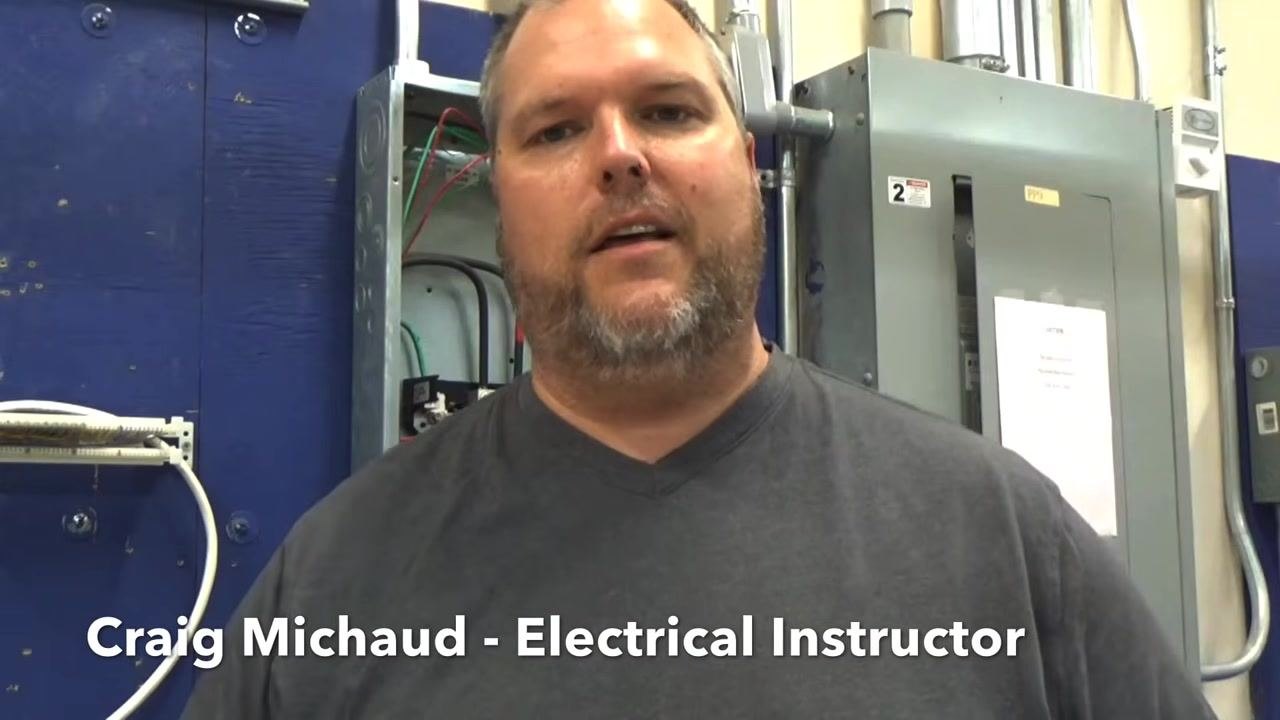
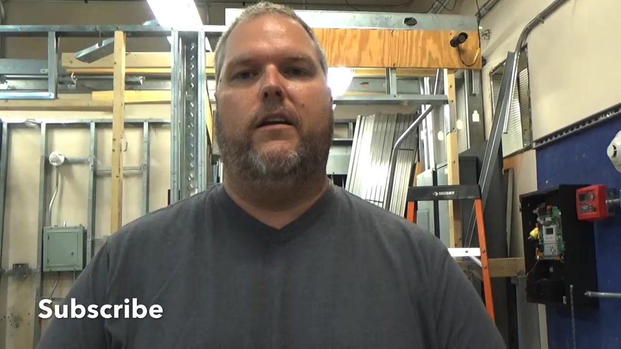
Video: Installing a GFCI Circuit Breaker by Craig Michaud- Electrical Instructor (2019). All credit for the demonstration goes to the creator; watch the original on YouTube. The written guide below was generated from this video by Docsie. Creator? Request a change or removal.
This guide explains how to install a GFCI circuit breaker in an electrical panel, including when this type of breaker is needed, how it differs from a standard breaker, and the wiring steps required to land it safely. Knowing how to install a GFCI circuit breaker correctly protects both equipment and people from ground faults, and in many jurisdictions it also satisfies code requirements for arc fault protection.
Purpose
The purpose of this procedure is to provide a clear, repeatable method for removing a standard breaker, identifying the correct circuit wiring, and installing and wiring a GFCI (or GFCI/Arc Fault combo) breaker in its place.
Scope
This procedure applies to residential and commercial electrical panels where a GFCI breaker is being installed to protect a circuit such as a pool pump or an area with multiple outlets where individual GFCI outlets are impractical. It covers panel safety, breaker identification, wire preparation, and final testing.

When to use a GFCI breaker
A GFCI (Ground Fault Circuit Interrupter) breaker protects circuits where ground faults may occur, such as pool pump circuits or areas with multiple outlets where installing individual GFCI outlets is not practical. GFCI breakers are common in commercial settings but are also used in residential applications for convenience or to meet code requirements.

A GFCI/Arc Fault combo breaker provides both ground fault and arc fault protection in a single device. This is useful where local code requires arc fault protection for new or replacement circuits (as in New England), since it lets you meet both requirements without installing a separate GFCI outlet and a separate arc fault breaker.

Required equipment and PPE
- New GFCI breaker (or GFCI/Arc Fault combo breaker) rated for the circuit
- Screwdriver
- Wire stripper
- Insulated tools
- Appropriate personal protective equipment for working inside an energized or de-energized panel
Safety precautions
Always turn off the main breaker before installing or replacing a breaker, especially if you have little or no experience working inside an electrical panel. Confirm the panel is de-energized before beginning any wiring work.
Experienced, qualified electricians may sometimes work with the main breaker on, but this is not recommended for beginners. If you are not comfortable or experienced with electrical work, always de-energize the main breaker before proceeding.

Understanding the GFCI breaker before you begin
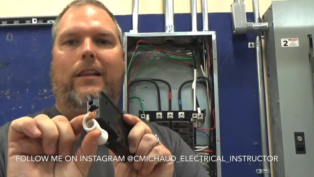
The example breaker used in this procedure is a Square D 20-amp GFCI breaker. Identify the trip button on the breaker (marked purple and labeled "trip"). The longer end of the breaker housing contains the ground fault (and, on combo units, arc fault) protection mechanism.
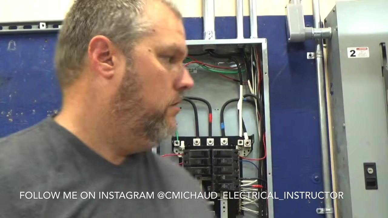
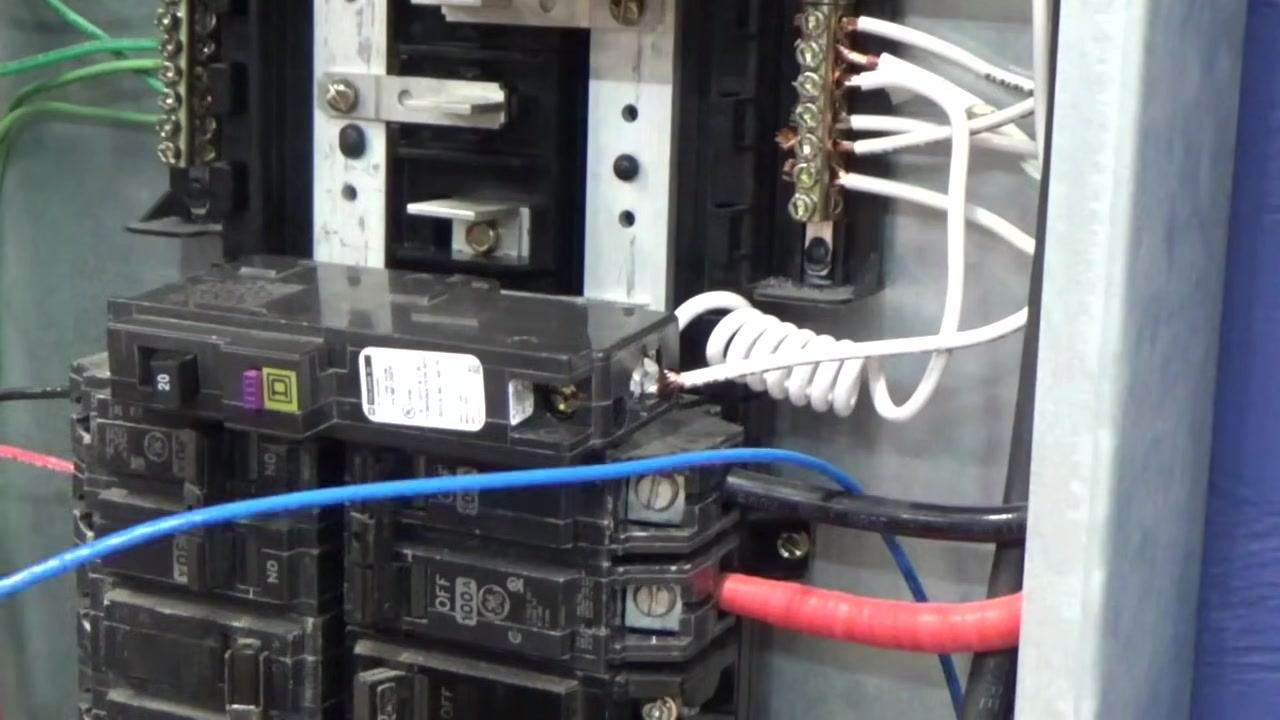
On a GFCI breaker, both the hot conductor (black wire) and the circuit's neutral conductor (white wire) are landed directly on the breaker itself, rather than the neutral being landed on the neutral bar as with a standard breaker.
For comparison: on a standard breaker, the hot wire connects to the breaker and the neutral wire connects to the neutral bar. On a GFCI breaker, both the hot wire and the circuit neutral wire connect to the breaker.
Inside the breaker is a relay and sensing mechanism that detects any difference in electrical potential between the outgoing and returning current. If the outgoing current does not match the returning current, the breaker trips to protect equipment and personnel. This differs from a standard breaker, which trips only when its rated capacity is exceeded.
When replacing a standard breaker with a GFCI breaker, you must locate the specific neutral wire that belongs to the circuit you are protecting, remove it from the neutral bar, and connect it to the GFCI breaker.
Step-by-step installation
1. Identify and remove the circuit neutral wire from the neutral bar. Locate the specific neutral wire that belongs to the circuit you are protecting and carefully disconnect it from the neutral bar. This wire will be connected directly to the GFCI breaker instead.
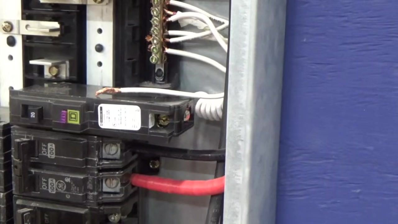
2. Prepare the GFCI breaker's pigtail wire. Locate the white, coiled pigtail wire attached to the GFCI breaker. This wire will be landed on the panel's neutral bar in a later step.
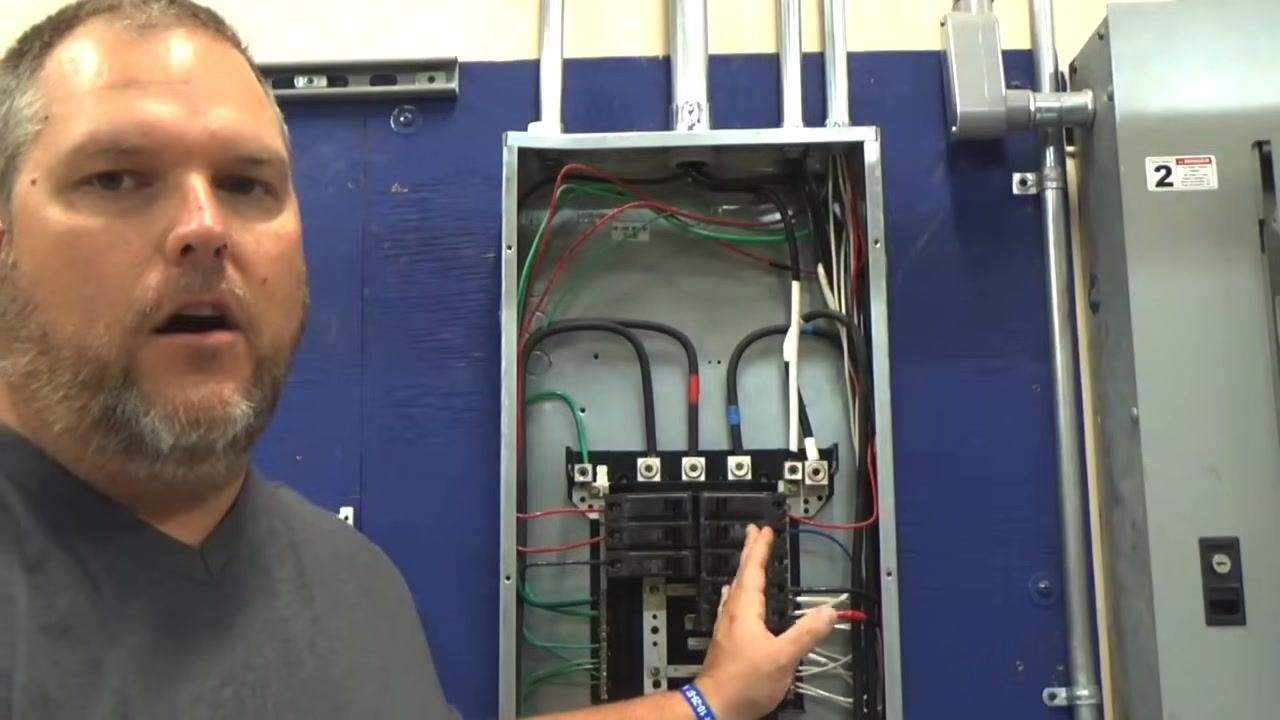
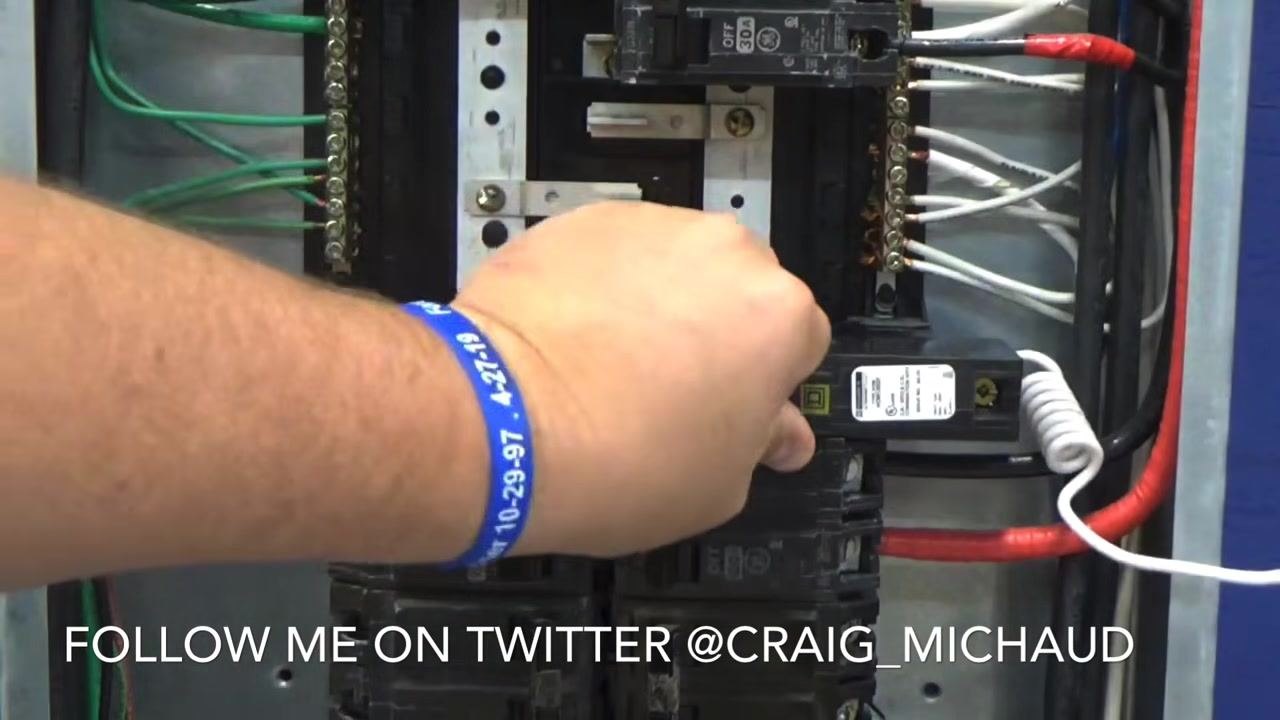
3. Select the installation slot. Identify an open slot in the panel, near the neutral bar, where the new GFCI breaker will be installed.
4. Prepare the wires for connection. Untwist or straighten the wires only as much as needed so they can be easily inserted into the breaker terminals and the neutral bar. Do not untwist more wire than necessary.
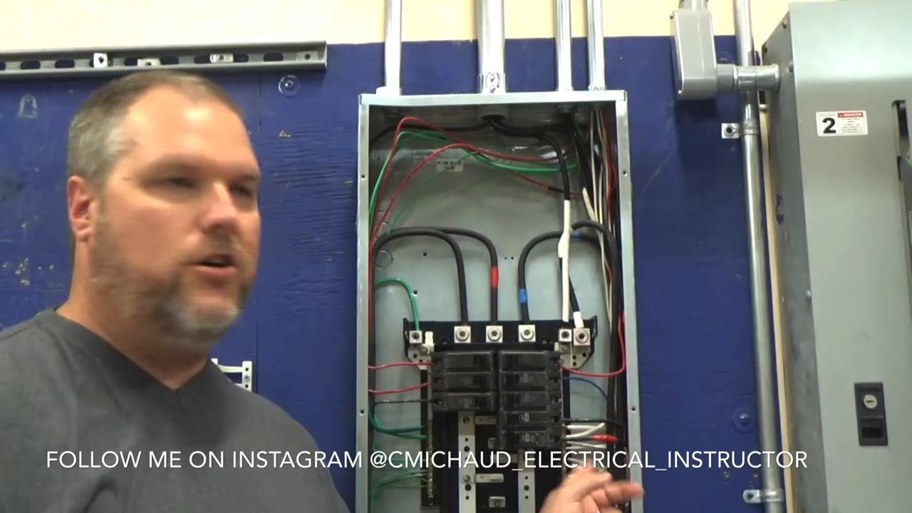
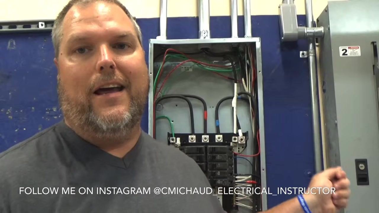
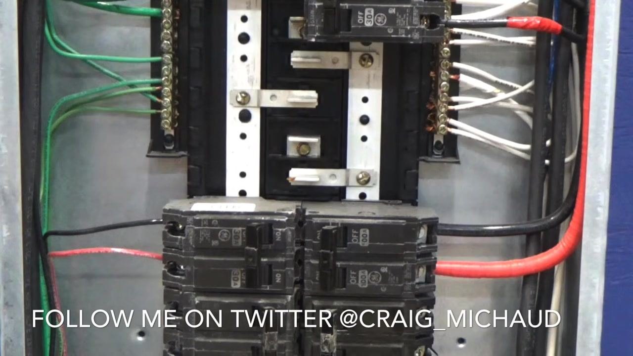
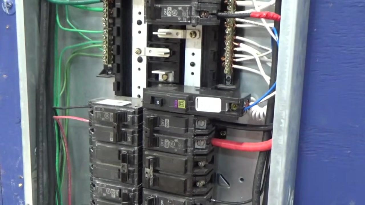
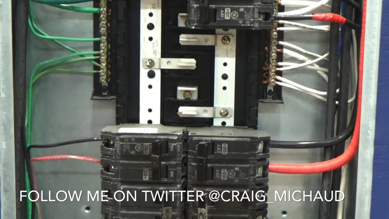
5. Inspect the panel layout before connecting wires. Note the arrangement of the neutral bar (with white wires) and the ground bar (with green wires), along with the black and red hot wires entering the breakers. Confirm the panel is clean and organized before making new connections.
6. Snap the new breaker into the panel. Confirm that the new circuit breaker is securely snapped into place and sits flush with the other breakers, with no looseness.
7. Prepare to land the breaker's neutral wire on the neutral bar. Locate the breaker's white coiled neutral wire and position it near an available terminal on the neutral bar, which already has several white wires connected.
8. Secure the neutral wire to the neutral bar. Insert the stripped end of the white neutral wire into an available slot on the neutral bar and tighten the screw with a screwdriver until the connection is firm and the wire does not move.
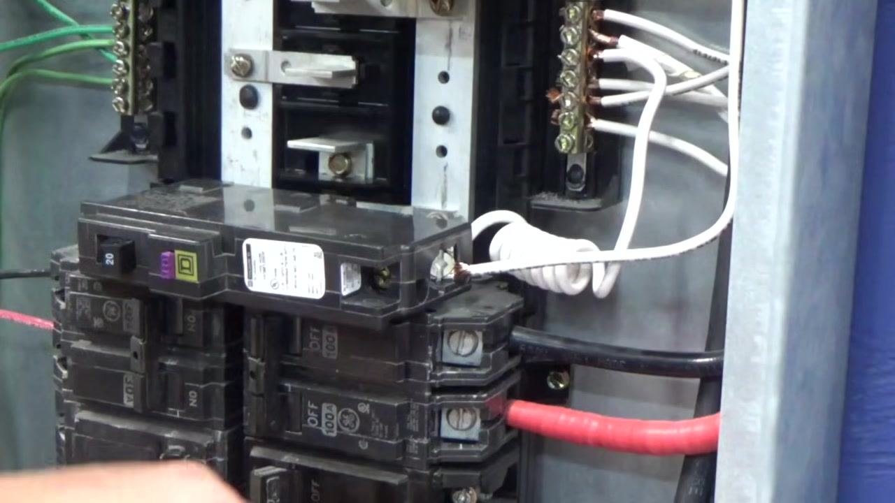
9. Remove the breaker to access its wiring terminal. Carefully take the breaker back out of its panel position so you can access the terminal for wiring. The white coiled wire remains attached, with its stripped end visible.
10. Insert the circuit neutral wire into the breaker terminal. Hold the breaker in one hand and the stripped wire in the other, then insert the stripped end into the terminal slot on the breaker.
11. Tighten the terminal screw to secure the wire. Tighten the terminal screw firmly so the wire is fully inserted and does not pull out when gently tugged.
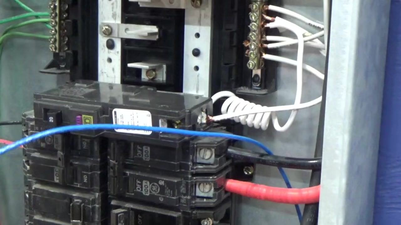
12. Verify the neutral connections before continuing. Confirm the breaker is properly seated in the panel and that the white neutral wire is securely attached to both the neutral bar and the breaker terminal. Inspect for loose wires or exposed copper. Note the blue wire now visible, which will be routed next.
13. Inspect the wired breaker before final placement. Confirm all wires connected so far are secure, and that the blue wire is routed and ready to be landed on the breaker.
14. Connect the hot (blue) wire to the breaker terminal. Insert the stripped end of the blue wire into the terminal slot on the breaker and tighten the screw with a screwdriver until the connection is tight and the wire does not move when gently tugged.
15. Prepare to reinstall the breaker. Confirm that both the white and blue wires are properly landed and secured, then hold the breaker in position, ready to snap it back into the panel.
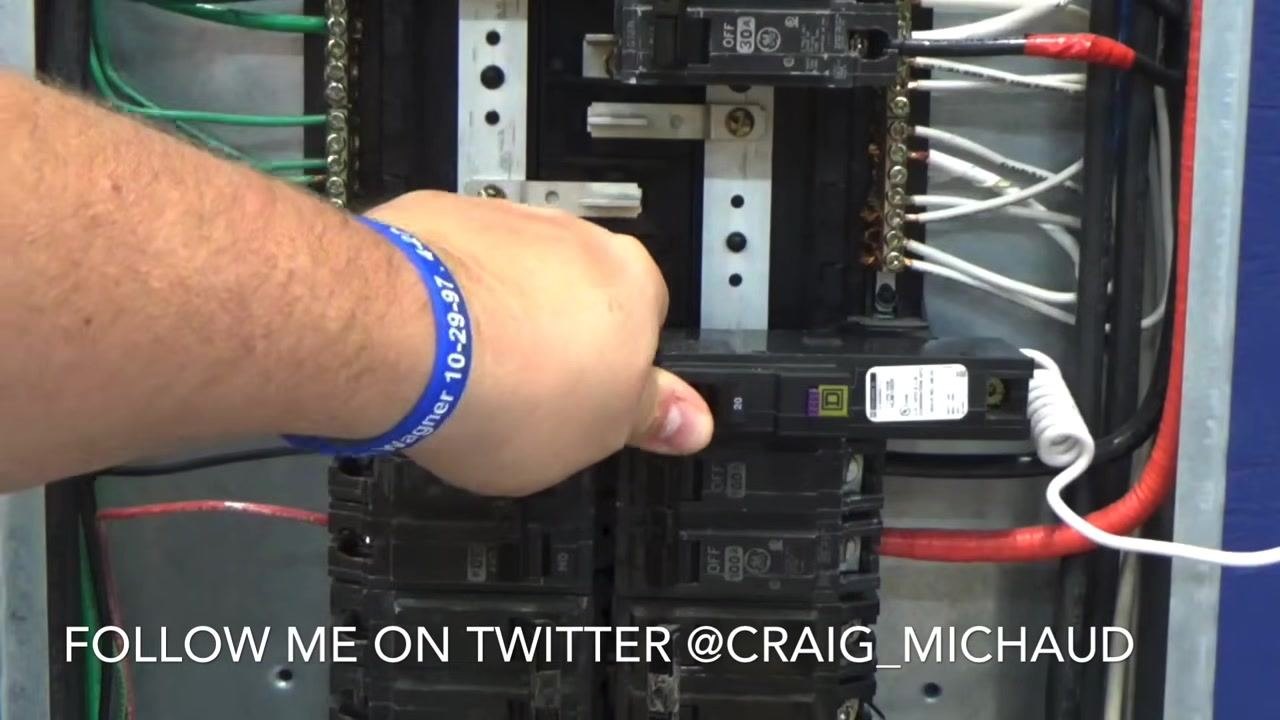
16. Snap the breaker back into place. Align the breaker with the panel's bus bar and mounting slot, then press it firmly into place until it clicks and sits flush with the other breakers.
17. Perform a final visual inspection. Confirm the breaker is properly installed and all wires are neatly routed, with the blue and white wires securely attached and no loose connections.
18. Turn the breaker on. Flip the switch on the newly installed breaker to the ON position and confirm that power is restored to the connected circuit.
Verification and summary
Before considering the installation complete, verify the following:
- The GFCI breaker's pigtail wire is connected to the neutral bar.
- Both the hot wire and the circuit's neutral wire from the protected circuit are connected directly to the breaker itself, not the neutral bar.
- All terminal screws are tight, with no loose wires or exposed copper.
- The breaker is fully seated in the panel and flush with adjacent breakers.
- The panel is free of tools and loose wires before the main power is restored.
- The breaker has been switched to the ON position and the connected circuit has power.
Only install GFCI breakers where required or recommended by applicable electrical code. Always ensure the main power is off before working inside an electrical panel, use insulated tools, and follow all local electrical codes and safety procedures. If you are unsure about any step, consult a licensed electrician.

What's next
Once the GFCI breaker is installed and verified, test the circuit using the breaker's trip/test function to confirm it responds correctly to a ground fault. Periodically re-test GFCI breakers as part of routine electrical maintenance to ensure continued protection.
Generation details: cost, quality tiers
Docsie billed 4,500 credits ($3.15) to analyze this 9-minute video at standard quality. The rewrite, template fill and Word/PDF exports were included. The same video at each quality tier:
| Quality | Frames sampled | Credits | Approx. cost |
|---|---|---|---|
| Draft | every 16-30 s | 2,250 | $1.57 |
| Standard (this guide) | every 8-15 s | 4,500 | $3.15 |
| Detailed | every 4-7 s | 9,000 | $6.30 |
| Ultra | every 1-3 s | 18,000 | $12.60 |
Credits priced at $0.70 per 1,000; plans include a monthly allowance. Enterprise customers on on-premise or bring-your-own-model deployments run this on their own inference and pay no per-video credits.
Generated by Docsie Video-to-Docs on 2026-09-14 from a 8-minute video. Screenshots are frames from the source video and belong to their creator, Craig Michaud- Electrical Instructor, whose original is embedded above. If you own this video and want the guide removed or credited differently, contact us and we will act within one business day.