
How to Do a Generator Load Bank Test
This procedure explains how to do a generator load bank test safely and accurately, from preparing electrical connections through monitoring the generator under load and securing equipment afterward. A load bank test confirms that a generator can deliver its rated power output by applying a controlled electrical load and verifying performance with both panel readings and an independent meter.
Video: Generator Load Bank Testing: The Basics by Woodstock Power Company (2022). All credit for the demonstration goes to the creator; watch the original on YouTube. The written guide below was generated from this video by Docsie. Creator? Request a change or removal.
This procedure explains how to do a generator load bank test safely and accurately, from preparing electrical connections through monitoring the generator under load and securing equipment afterward. A load bank test confirms that a generator can deliver its rated power output by applying a controlled electrical load and verifying performance with both panel readings and an independent meter.
Purpose
The purpose of this procedure is to verify that a generator can supply its rated power under a simulated real-world load. A load bank applies an electrical load to the generator so that its output can be measured and confirmed against expected values.
Scope
This procedure covers preparing the generator and load bank connections, setting up voltage and load steps, verifying readings with an independent meter, running a staged load test, and inspecting and securing equipment after the test is complete.
Required equipment
- Generator under test (example used: 30 kW generator configured for 120/240V output, rated for approximately 125 amps)
- Load bank rated for the test (example used: 55 kW load bank set up for 120/240V operation)
- Heavy-duty connection cables and ground cable
- A reliable electrical meter with test leads (such as a clamp meter)
- Access to the generator's breaker panel and the load bank's control panel
Procedure
Understand the purpose of load bank testing
Load bank testing is performed to ensure a generator can deliver its rated power output. A load bank is a device that applies an electrical load to the generator, simulating real-world usage and verifying the generator's performance.
Review the generator and load bank specifications
Confirm the ratings of both units before starting. In this example, the generator is rated at 30 kW for 120/240V output and can supply approximately 125 amps, while the load bank is rated at 55 kW and is set up for 120/240V operation.
Plan the load test duration and steps
Conduct the load test for approximately 30 minutes, staged as follows:
- Apply 20% load for the first 10 minutes
- Increase to 50% load for the next 10 minutes
- Apply full load for the remaining time
Locate the generator's breaker panel
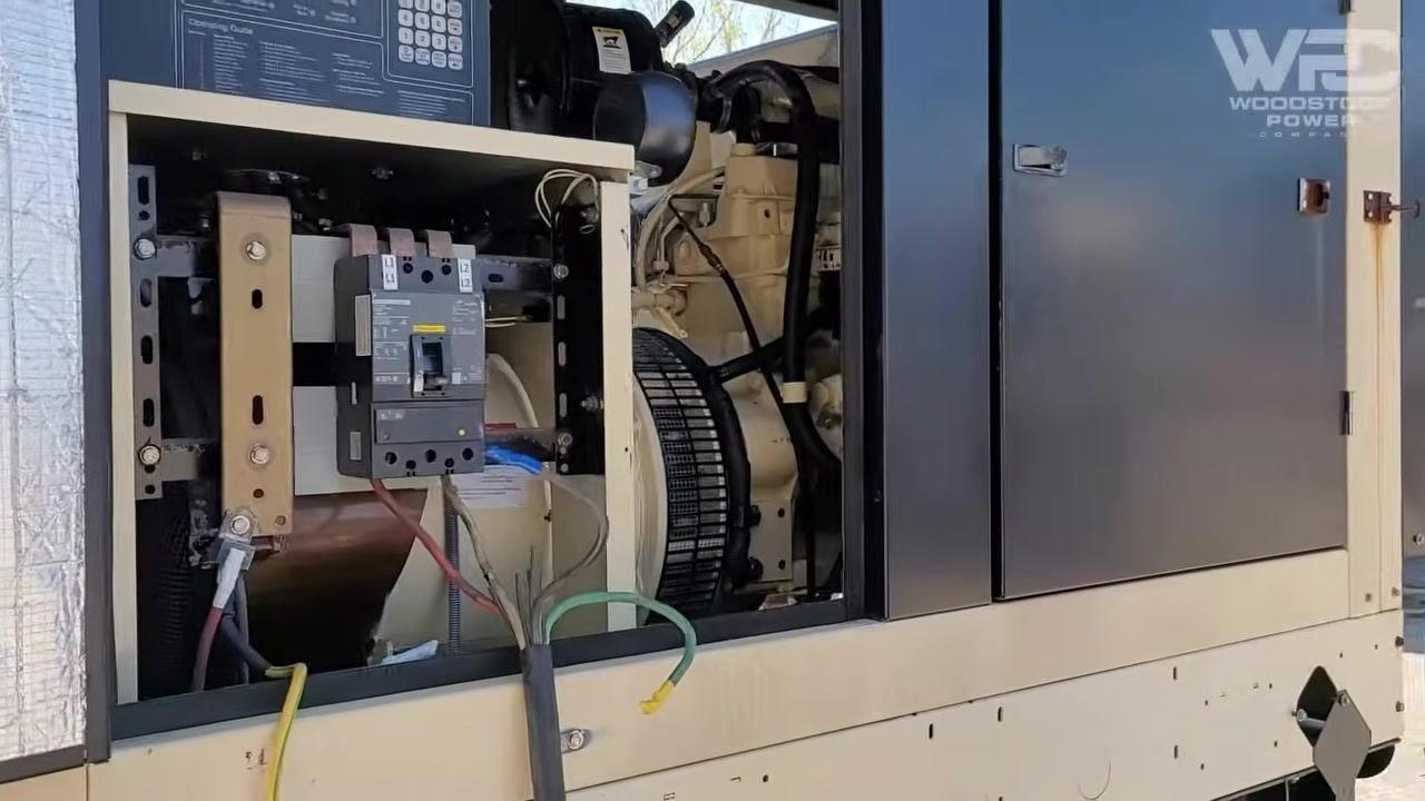
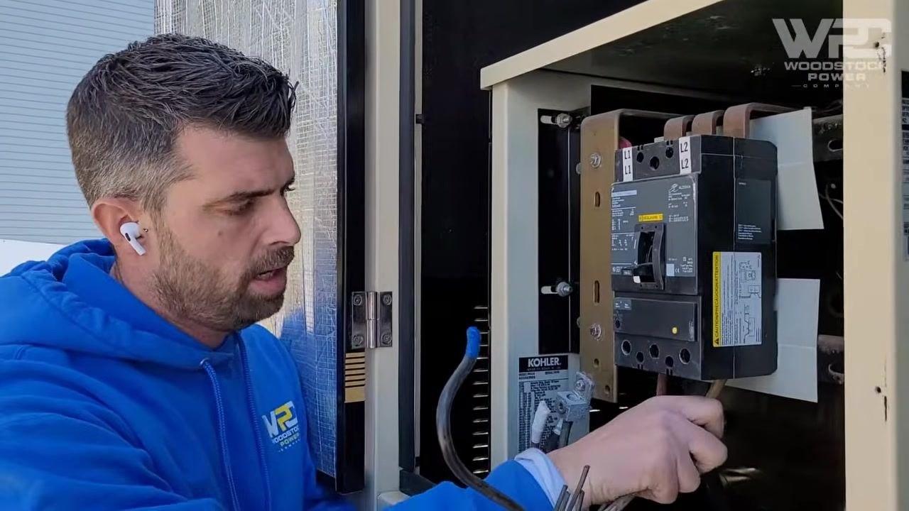
Open the breaker panel to access the connection points. Identify the customer connection terminals at the top and the user connection terminals at the bottom.
Prepare the electrical connections
For 120/240V testing, connect two hot leads to the phase A and phase C terminals on the breaker. Ensure the connections are secure and properly tightened.
Connect the load bank
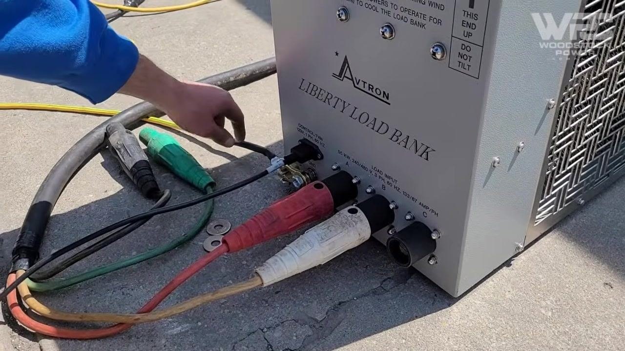
Attach the two hot leads from the generator breaker to the corresponding input terminals on the load bank, typically labeled A and B. Connect the load bank's control fan to a 120V supply to ensure proper cooling during the test, and ground the load bank according to safety requirements.
Double-check all connections
Verify that all cables are securely attached and that the load bank is properly grounded. Confirm that the load bank is set for the correct voltage — 120/240V in this case — before proceeding.
Set the load bank voltage and load steps
Set the voltage selector switch on the load bank to 240V. Use the available load step switches to achieve the desired test loads:
- Use the 20 kW and 10 kW switches to reach a total of 30 kW
- Alternate between the 10 kW and 5 kW switches to achieve 25% and 50% load as needed
Not all load steps may be used; select the combination that matches your test plan.
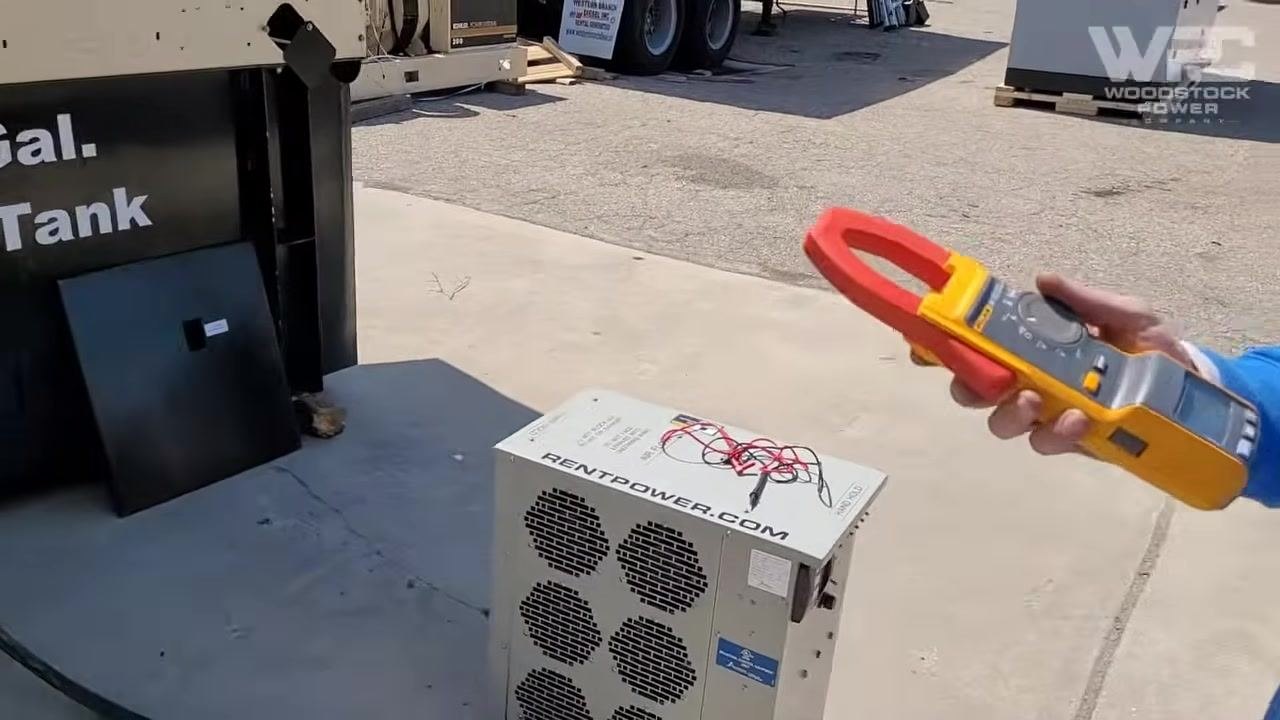
Confirm all connections and grounding
Ensure the cables from the generator breaker are securely connected to the load bank input terminals, and verify the load bank is properly grounded. Confirm that the generator itself is also grounded to prevent electrical hazards.
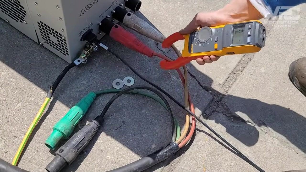
Perform a safety check of the work area
Ensure the work area is clean and free of any foreign objects. Remove any items that could vibrate or move during generator startup, as this could cause shorts or other hazards.
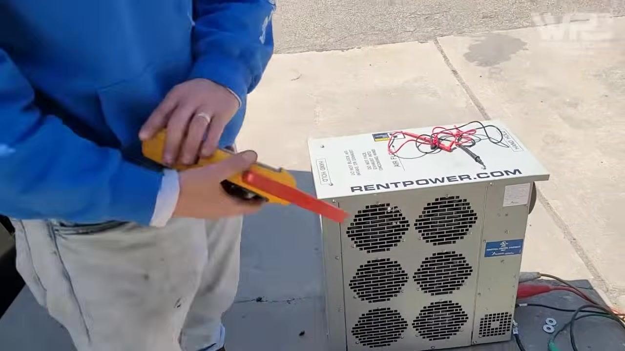
Prepare to measure electrical values
Do not rely solely on the generator panel or load bank panel readings. Use a reliable electrical meter, such as a clamp meter, to independently verify amperage and voltage. Gather your meter and test leads and confirm they are in good working condition.
Test each lead individually
Use the clamp meter to measure the current on each individual lead connected to the load bank. Compare the measured amperage to the values displayed on the load bank and generator panels to ensure consistency.
Verify voltage and polarity
Always check the voltage directly at the leads using your meter, and confirm it matches the expected 120/240V output regardless of what is displayed on the panels. Check both positive and negative leads for correct polarity and voltage.
Check voltage across both phases to ground
Use your electrical meter to measure voltage from phase A to ground and from phase B to ground. Confirm you are reading 120V from each phase to ground and 240V across both phases. Only proceed if these voltage readings are correct.
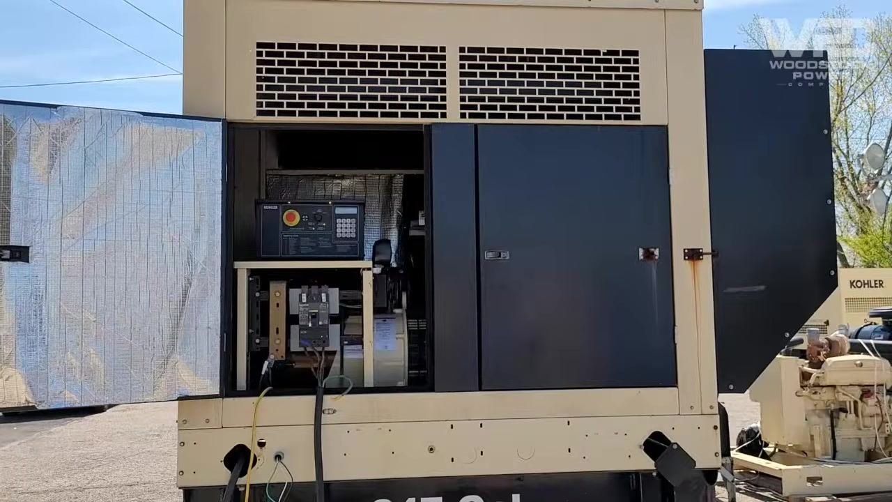
Observe generator and load bank status
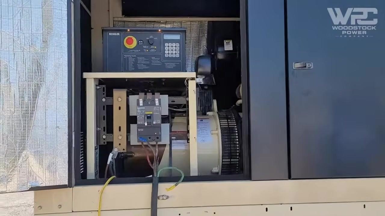
Inspect the generator control panel and ensure all connections remain secure. Confirm the generator is running and the breaker is engaged.
Confirm generator model and identification
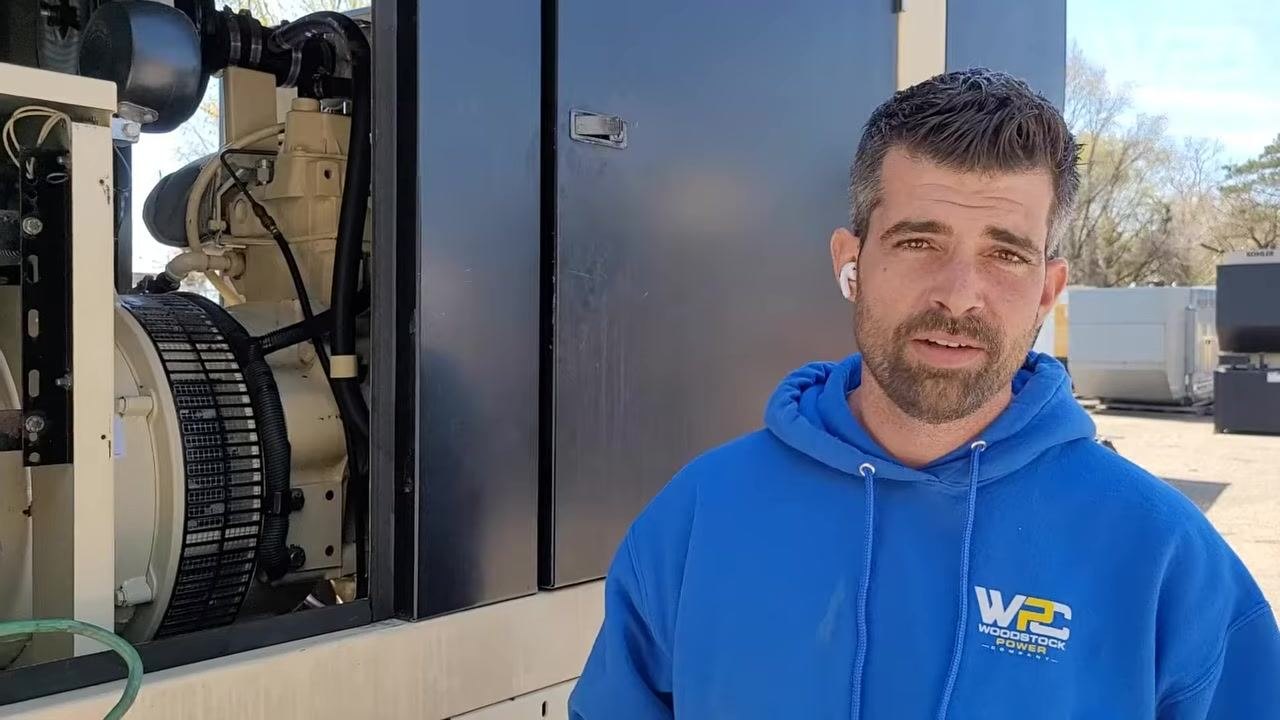
Verify the generator model and serial number for documentation purposes. In this example, the label reads "KOHLER POWER SYSTEMS 30" with serial number "M154XC078".
Inspect load bank cable connections
Ensure all cables, including ground and phase leads, are securely attached to the load bank. Visually check for any loose or disconnected cables.
Read current values on the load bank panel
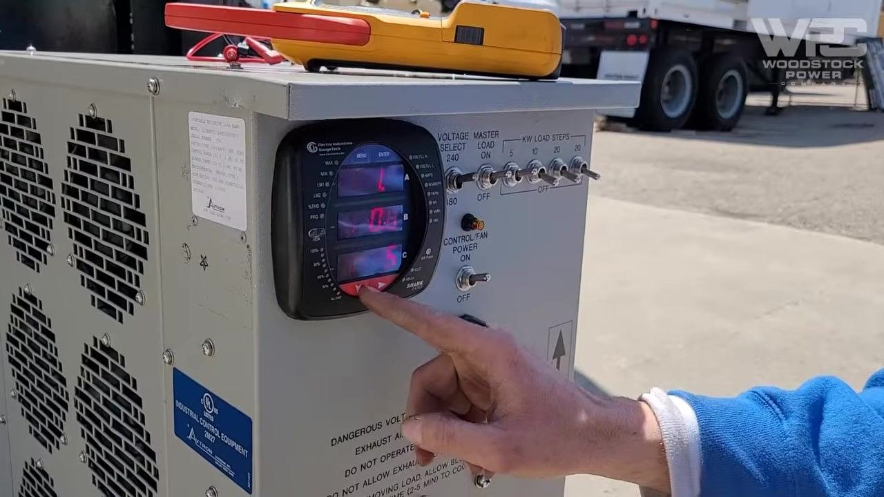
Observe the digital ammeter on the load bank control panel and note the current readings for each phase (A, B, C). In this example, the readings were approximately 31 amps per phase.
Confirm current readings with a clamp meter
Use a clamp meter to independently measure the current on each phase lead, and compare the reading to the load bank panel display. In this example, the clamp meter showed 31.7 amps on one phase.
Adjust load steps as needed
If current readings do not match expected values, adjust the load step switches on the load bank. In this example, the switches were adjusted to achieve a reading of 42 amps on IMD.
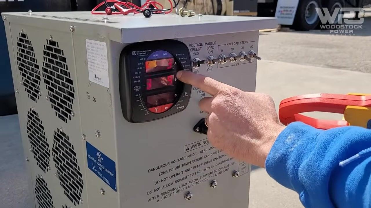
Confirm final load current on generator instrumentation
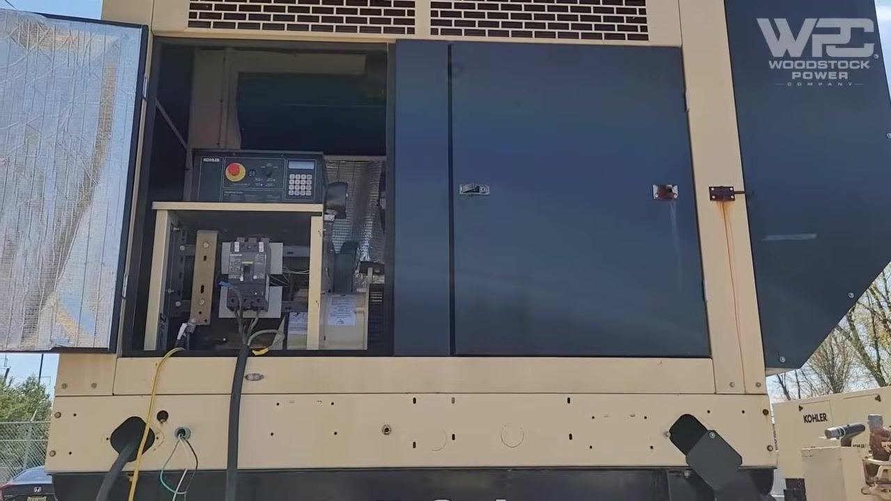
Observe the generator control panel to verify the final load current after adjustments. Ensure the generator is running with the load applied and all access doors are open for monitoring. Confirm that the load current matches the target value — 42 amps on IMD in this example.
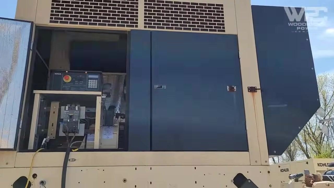
Inspect the load bank control panel
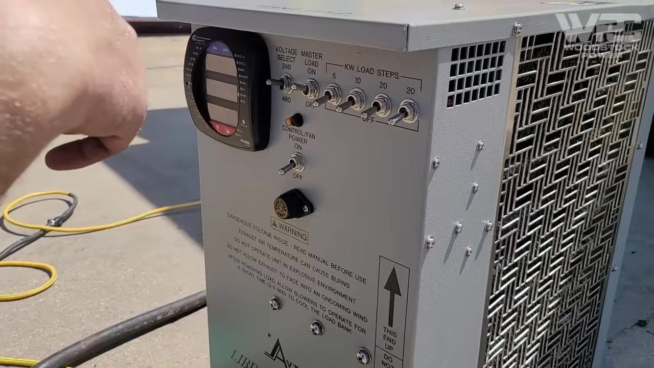
Approach the load bank control panel and observe the digital display along with the array of toggle switches labeled for voltage selection, master load, and kW load steps. Note the control/fan power switch and warning labels regarding voltage and exhaust air temperature. Ensure all switches are in their correct positions for your test setup and confirm the digital display is active and reading values.
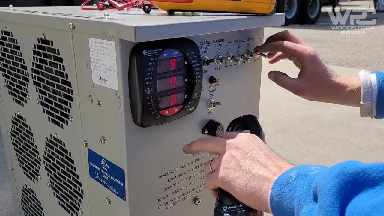
Monitor frequency during the load test
Observe the digital display for frequency readings and confirm the frequency is stable at 60 Hz with no drop detected. Ensure the control/fan power switch remains ON throughout the test.
Verify system status
Check the digital display for any abnormal readings, and press the navigation or confirmation button on the display panel to cycle through system parameters. Confirm that all readings are within expected ranges and the system is operating normally.
Check oil pressure
Continue monitoring the digital display for oil pressure and other critical engine parameters. Ensure oil pressure remains within safe limits throughout the test.
Look for abnormalities
Inspect the control panel and digital display for any warning indicators or values that are out of place, and confirm that no unexpected readings or issues are present.
Conclude the load bank test
Once the display and panel checks are complete with no abnormalities, the load bank test procedure is finished.
Review the test duration
Confirm that a 30-minute load bank test was performed on the generator and that all test steps were completed within the specified time frame.
Inspect generator connections post-test
Visually inspect the generator's internal components and wiring after the test. Check that all cables, breakers, and connections are secure and undamaged, and ensure the generator is in a safe state before closing any access panels.
Finalize and secure equipment
Confirm all equipment is powered down and safe to handle. Close and secure all access panels on the generator, and ensure the area is clean with all tools accounted for.
Verification and summary
A successful generator load bank test confirms the following:
- All electrical connections were secure and properly grounded before the test began
- Voltage, polarity, and current readings on the panels matched independent clamp meter measurements
- The generator maintained stable frequency at 60 Hz and safe oil pressure throughout the 30-minute test
- No abnormal readings or warning indicators appeared on the load bank or generator control panels
- The load current reached the target value specified in the test plan
- All connections and internal components were inspected and found secure after the test, and equipment was safely powered down and secured
By following these steps, you ensure the generator and load bank are set up correctly, that all measurements are independently verified, and that safety protocols are followed throughout the entire load bank testing procedure.
Generation details: cost, quality tiers
Docsie billed 3,500 credits ($2.45) to analyze this 7-minute video at standard quality. The rewrite, template fill and Word/PDF exports were included. The same video at each quality tier:
| Quality | Frames sampled | Credits | Approx. cost |
|---|---|---|---|
| Draft | every 16-30 s | 1,750 | $1.22 |
| Standard (this guide) | every 8-15 s | 3,500 | $2.45 |
| Detailed | every 4-7 s | 7,000 | $4.90 |
| Ultra | every 1-3 s | 14,000 | $9.80 |
Credits priced at $0.70 per 1,000; plans include a monthly allowance. Enterprise customers on on-premise or bring-your-own-model deployments run this on their own inference and pay no per-video credits.
Generated by Docsie Video-to-Docs on 2026-09-14 from a 6-minute video. Screenshots are frames from the source video and belong to their creator, Woodstock Power Company, whose original is embedded above. If you own this video and want the guide removed or credited differently, contact us and we will act within one business day.