
How to Read Aircraft Blueprints
Learning how to read aircraft blueprints starts with recognizing the different line types used in technical drawings and understanding what each one communicates. This standard operating procedure walks Aircraft Maintenance Technicians (AMTs) through the standard line types found in aircraft drawings, a foundational skill for anyone preparing for the FAA Airframe and Powerplant (A&P) Certificate.
Video: Aircraft Drawings: Lines and Their Meaning by ETAPro Airframe and Powerplant Refresher Courses (2020). All credit for the demonstration goes to the creator; watch the original on YouTube. The written guide below was generated from this video by Docsie. Creator? Request a change or removal.
Learning how to read aircraft blueprints starts with recognizing the different line types used in technical drawings and understanding what each one communicates. This standard operating procedure walks Aircraft Maintenance Technicians (AMTs) through the standard line types found in aircraft drawings, a foundational skill for anyone preparing for the FAA Airframe and Powerplant (A&P) Certificate.
Purpose
This procedure explains how to identify and interpret the various line types used in aircraft technical drawings, including phantom lines, center lines, outline lines, dimension lines, hidden lines, cutting plane lines, break lines, extension lines, and section lines.
Scope
This procedure applies to AMTs and candidates preparing for the FAA A&P certification exams who need to interpret aircraft drawings as part of their training or on-the-job responsibilities.
Prerequisites
- A basic understanding of technical drawing conventions.
- Confirmation of your eligibility to sit for the FAA A&P certification exams (see Step 12).
Required materials
- Sample aircraft drawings or blueprints for reference and practice.
- A note-taking method to record line types and their meanings as you review each drawing.
Step-by-step procedure
Step 1: Identify phantom lines
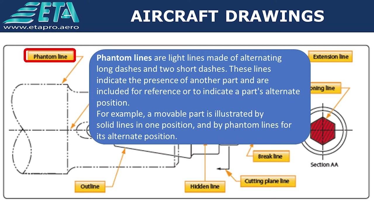
Phantom lines are light lines made of alternating long dashes and two short dashes. They indicate the presence of another part for reference, or they show a part's alternate position. For example, a movable part may be shown with solid lines in one position and phantom lines marking its alternate position.
Step 2: Recognize center lines
Center lines consist of alternating long and short dashes. You use them to show the middle of a symmetrical part, such as the center of a hole. The exact center is marked by the intersection of two short dashes.
Step 3: Identify outline or visible lines
Outline or visible lines illustrate the visible parts of an object. These are medium-weight solid lines and are the most common line type you will encounter in aircraft drawings.
Step 4: Understand dimension lines
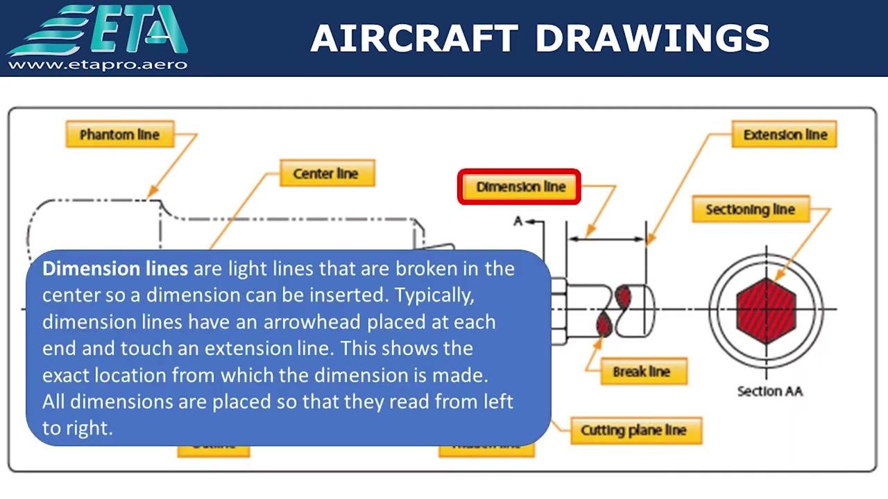
Dimension lines are light lines broken in the center to allow for the insertion of a dimension value. Each end typically carries an arrowhead and touches an extension line, showing the exact location from which the dimension is measured. All dimensions are placed so that they read from left to right.
Step 5: Identify hidden lines
Hidden lines indicate invisible edges or contours of an object. You recognize them as medium-weight dashed lines.
Step 6: Recognize cutting plane lines
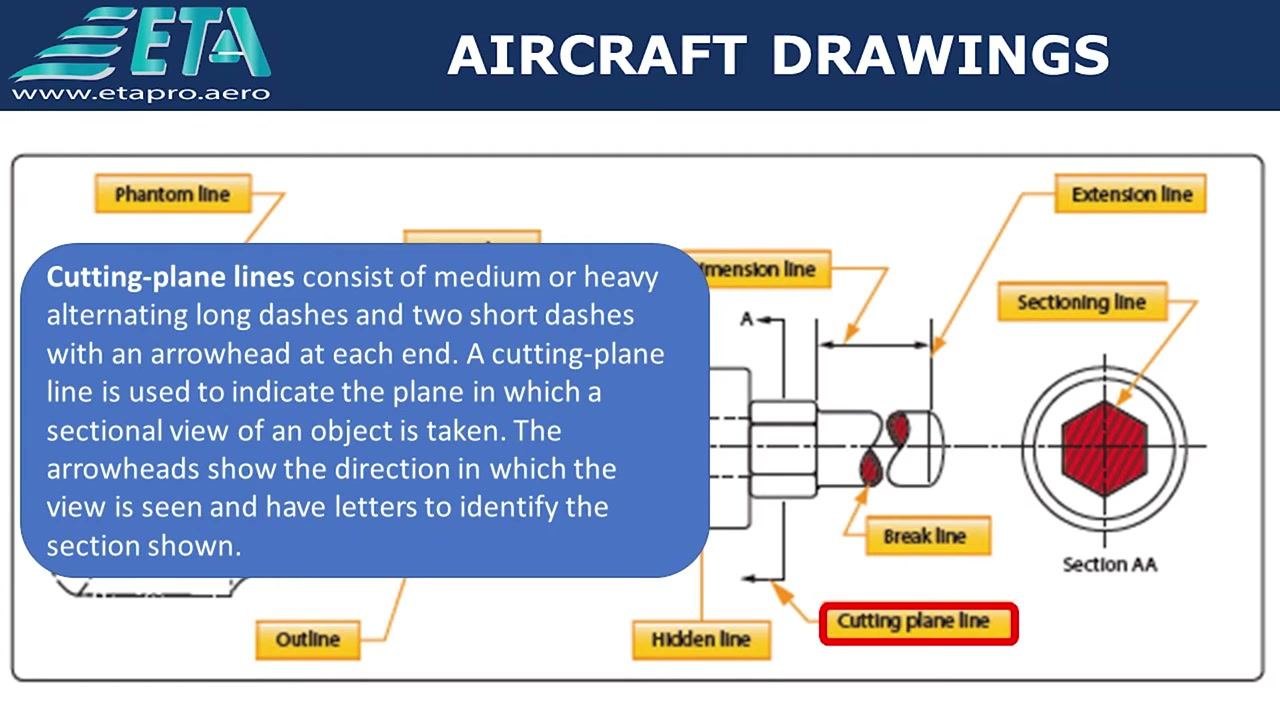
Cutting plane lines consist of medium or heavy alternating long dashes and two short dashes, with an arrowhead at each end. These lines indicate the plane in which a sectional view of an object is taken, and the arrowheads show the direction from which the view is seen. Letters on the cutting plane line identify the corresponding section — for example, a line labeled "AA" corresponds to "Section AA."
Step 7: Understand break lines
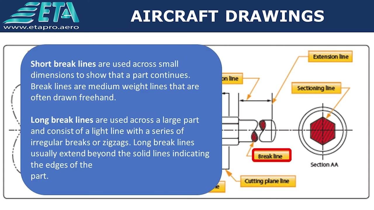
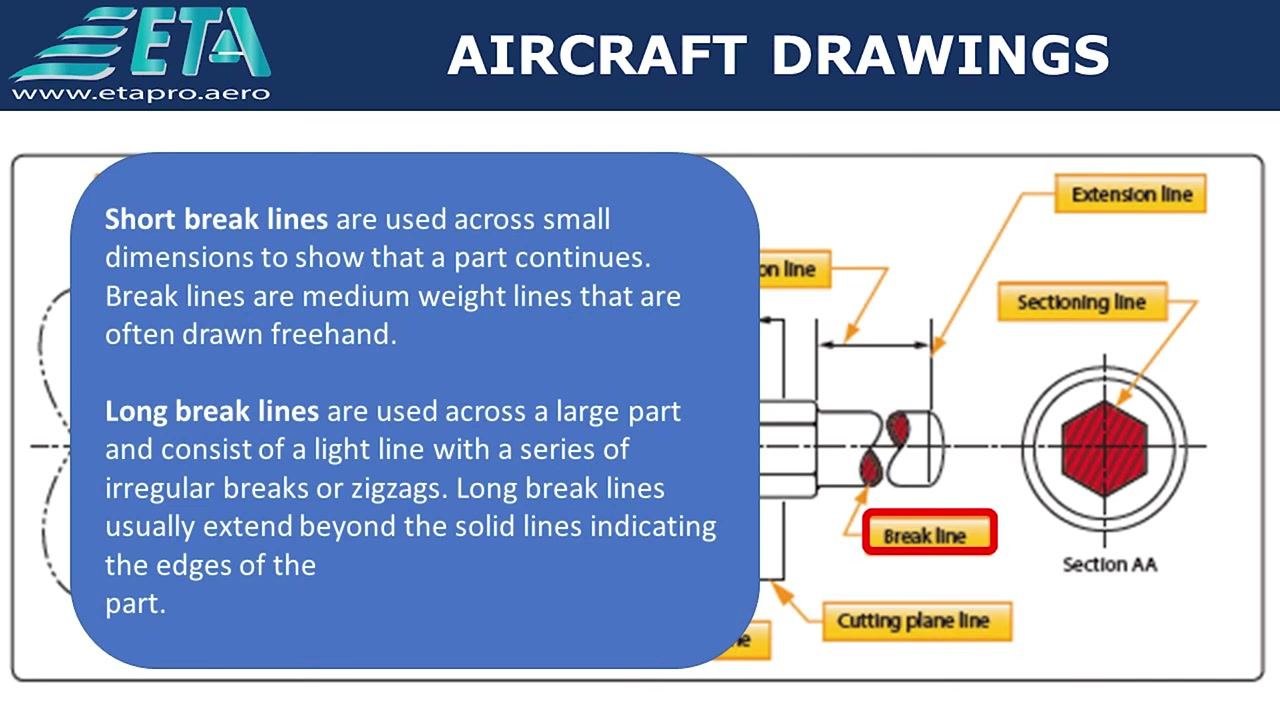
Short break lines, used across small dimensions, show that a part continues; these are medium-weight lines, often drawn freehand. Long break lines, used across large parts, are light lines with a series of irregular breaks or zigzags, and they usually extend beyond the solid lines that indicate the edges of the part.
Step 8: Recognize extension lines
Extension lines are light lines that extend from the point where a measurement is made. These lines do not touch the visible lines of an object; they sit approximately 1/16 inch from a part's edge.
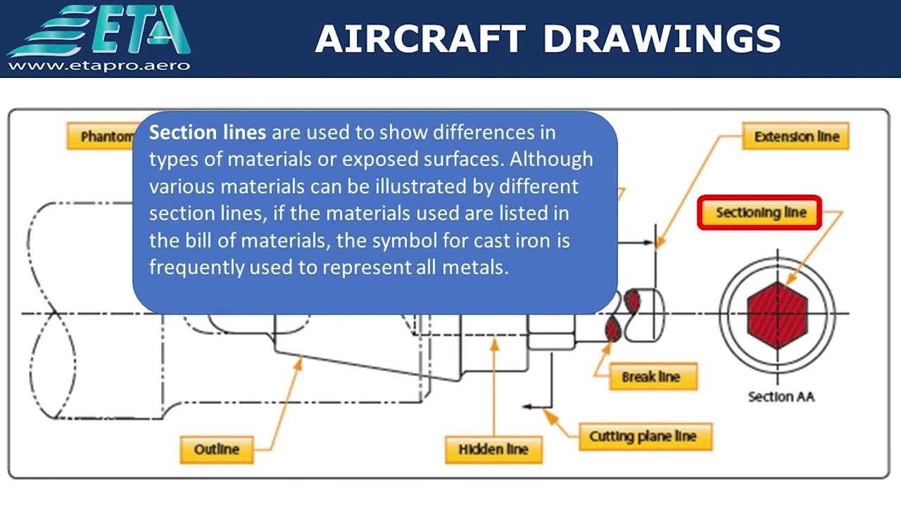
Step 9: Identify section lines
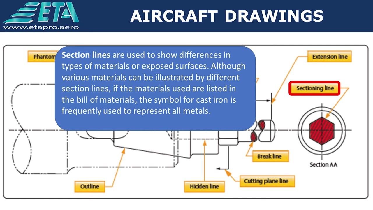
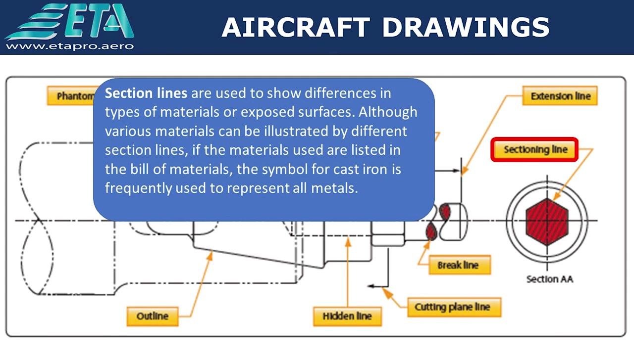
Section lines show differences in types of materials or exposed surfaces, with different materials illustrated by different section line patterns. If the materials are listed in the bill of materials, the cast iron symbol is frequently used to represent all metals for simplicity.
Step 10: Review section lines in context
Review a full drawing to see how section lines relate to the other line types you have learned. Confirm you can distinguish the outline, hidden line, break line, extension line, cutting plane line, and sectioning line together in one drawing.
Step 11: Recognize the cast iron symbol
When reviewing sectioned areas in a drawing, look for the cast iron symbol if the bill of materials lists the materials used. Remember that this symbol may represent all metals, not just cast iron, since it is used for simplicity in technical documentation.
Step 12: Verify your certification eligibility
Before applying for the FAA A&P certification exams, confirm you meet the experience requirements: 18 months of practical experience for either airframe or powerplant, or 30 months of combined experience covering both. This experience is a prerequisite for taking the exams.
Verification and summary
After completing this procedure, you should be able to:
- Accurately interpret phantom, center, outline, dimension, hidden, cutting plane, break, extension, and section lines in aircraft technical drawings.
- Recognize how standardized symbols, such as the cast iron symbol, simplify material representation in technical documentation.
- Assess your own readiness for the FAA A&P certification exams based on the 18-month or 30-month experience requirements.
What's next
With line types confirmed, practice applying this knowledge by reviewing full aircraft drawings and identifying each line type in context. If you have not yet met the 18-month or 30-month experience requirement, continue accumulating qualifying experience before scheduling your FAA A&P certification exams.
Generation details: cost, quality tiers
Docsie billed 2,000 credits ($1.40) to analyze this 4-minute video at standard quality. The rewrite, template fill and Word/PDF exports were included. The same video at each quality tier:
| Quality | Frames sampled | Credits | Approx. cost |
|---|---|---|---|
| Draft | every 16-30 s | 1,000 | $0.70 |
| Standard (this guide) | every 8-15 s | 2,000 | $1.40 |
| Detailed | every 4-7 s | 4,000 | $2.80 |
| Ultra | every 1-3 s | 8,000 | $5.60 |
Credits priced at $0.70 per 1,000; plans include a monthly allowance. Enterprise customers on on-premise or bring-your-own-model deployments run this on their own inference and pay no per-video credits.
Generated by Docsie Video-to-Docs on 2026-09-14 from a 3-minute video. Screenshots are frames from the source video and belong to their creator, ETAPro Airframe and Powerplant Refresher Courses, whose original is embedded above. If you own this video and want the guide removed or credited differently, contact us and we will act within one business day.