
How to Do a Borescope Inspection on a Jet Engine
A borescope inspection lets you examine turbine and compressor blades inside a jet engine without disassembling the unit. This procedure explains how to perform a borescope inspection on a jet engine step by step, from positioning the camera at the inspection port to scanning each blade, identifying surface defects, and documenting your findings for maintenance records.
Video: ENGINE BORESCOPE INSPECTION AFTER BIRD STRIKE - AIRBUS A330 by Aircraft Maintenance Engineer (2019). All credit for the demonstration goes to the creator; watch the original on YouTube. The written guide below was generated from this video by Docsie. Creator? Request a change or removal.
A borescope inspection lets you examine turbine and compressor blades inside a jet engine without disassembling the unit. This procedure explains how to perform a borescope inspection on a jet engine step by step, from positioning the camera at the inspection port to scanning each blade, identifying surface defects, and documenting your findings for maintenance records.
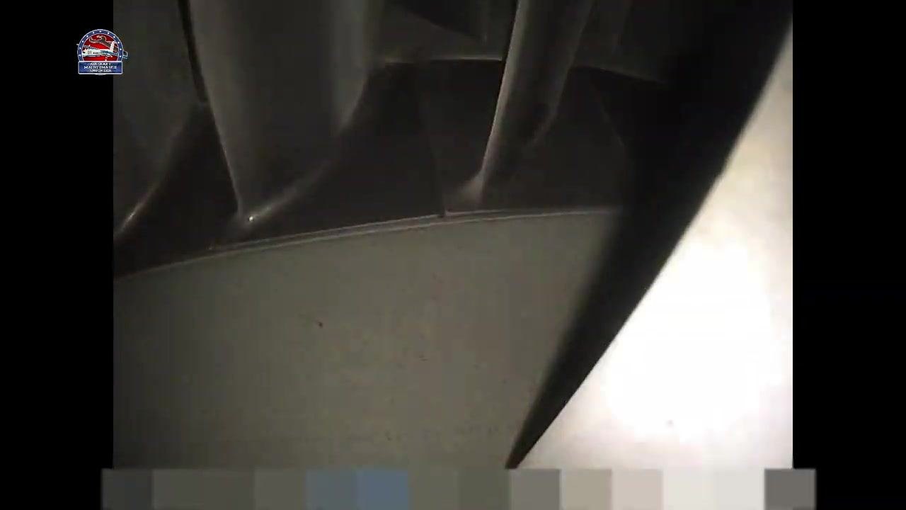
Purpose
This procedure describes how to visually inspect turbine and compressor blades inside a jet engine using an inspection camera or borescope, in order to detect surface defects, structural damage, corrosion, and abnormal wear before they affect engine performance.
Scope
This procedure applies to the visual inspection of turbine blades, compressor blades, blade roots, blade platforms, and associated fasteners using an inspection camera inserted through an engine inspection port.
Required equipment
- Inspection camera or borescope with integrated lighting
- Sufficient lighting to reveal surface detail on metallic components
- A documentation tool (camera capture or recording function) to record findings for maintenance records
Part 1: Inspect turbine blades for surface defects
-
Position the borescope on the first blade
- Position the inspection camera to obtain a close-up view of the first turbine blade or cylindrical component.
- Confirm the lighting is sufficient to reveal surface detail.
- Observe the surface for any visible defects or irregularities.
-
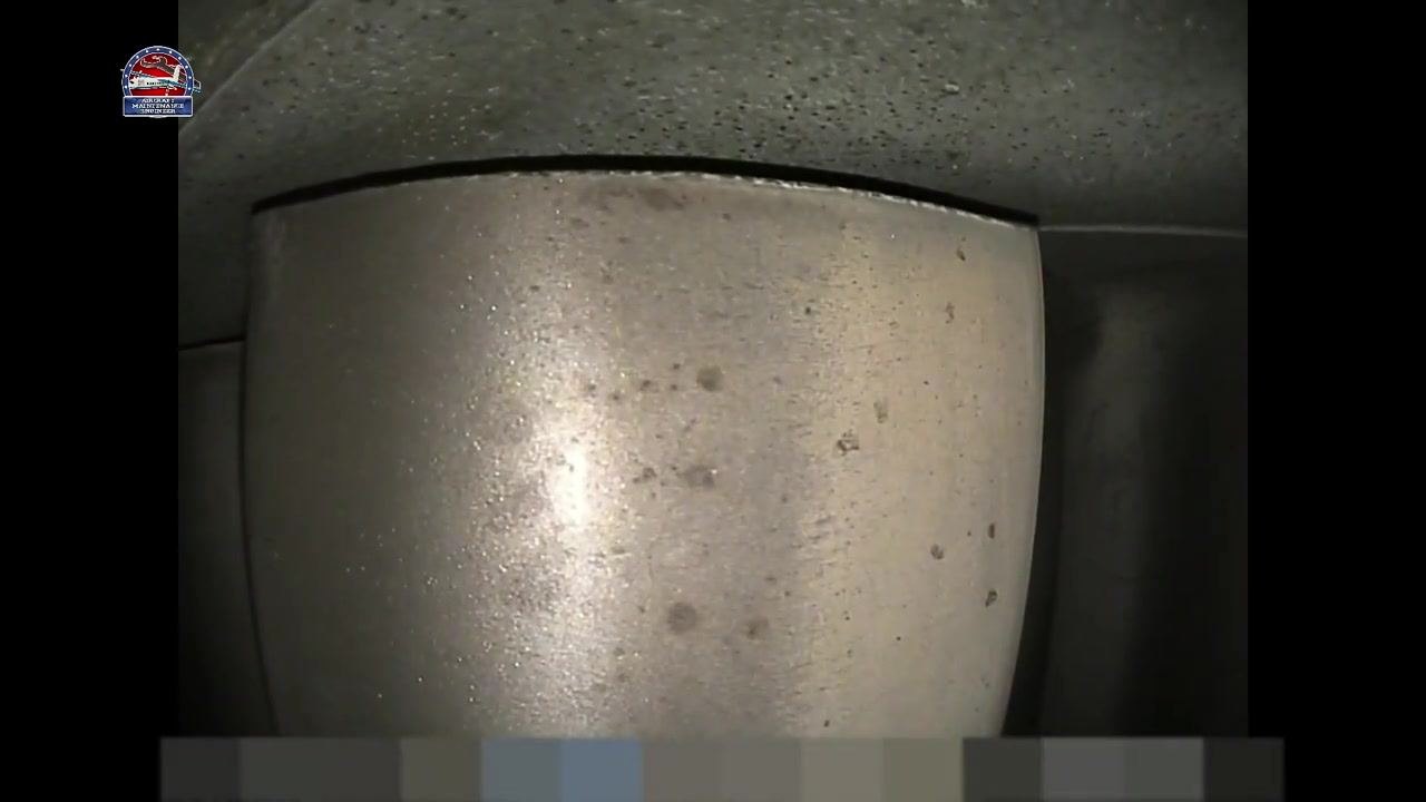
Scan the blade surface for pitting or contamination
- Slowly move the camera along the surface of the component.
- Watch for changes in texture, color, or the appearance of spots or marks.
- Small dark spots on the surface indicate possible pitting or contamination.
-
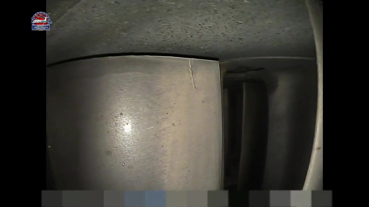
Identify surface cracks at the blade edge
- Adjust the camera angle to reveal the top edge of the component.
- Inspect carefully for cracks or fractures along the edge.
- A visible crack at the top edge is a critical defect; document its location and extent for maintenance records.
-
Inspect the adjacent blade
- Move the camera to the right to inspect the next blade or component.
- Continue checking for cracks, chips, or other surface defects.
- The crack remains visible while the adjacent blade comes partially into view.
-
Detect major deformations on the next blade
- Progress the camera further to inspect the next section.
- Look for major deformations such as dents, chips, or missing material.
- A significant chip or missing section on the left edge indicates severe damage; record it for urgent maintenance action.
-
Re-examine the damaged area
- Move the camera back to the previously damaged area to confirm the extent of the defect.
- Document the defect from multiple angles to ensure it is clearly recorded.
-
Verify no additional nearby defects
- Continue scanning the surface to confirm no additional defects are present.
- The chip and crack remain visible; no new defects appear in this view.
-
Inspect the next blade for additional cracks
- Move the camera to inspect the next blade or component in the sequence.
- Look for cracks, chips, or other surface irregularities.
- A long crack along the top edge indicates another area of concern; document its location and extent.
-
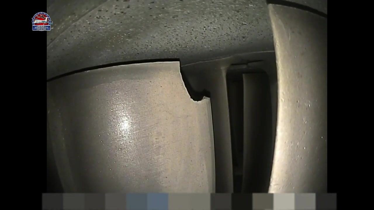
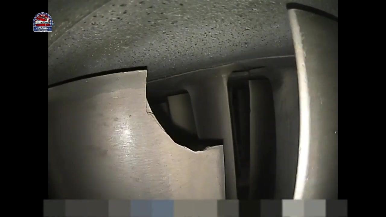
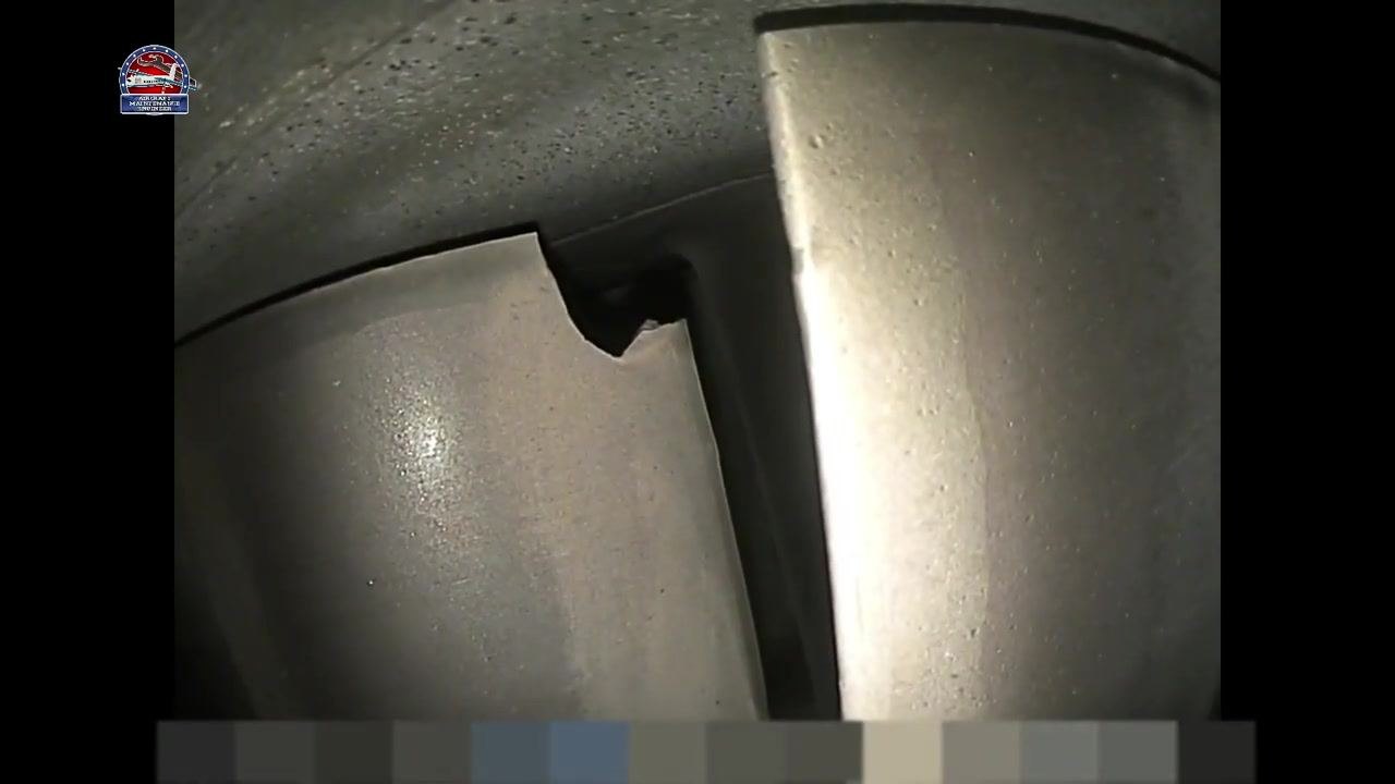
Examine the full extent of blade damage
- Focus the camera on the top edge of the blade.
- A large, irregular chip or missing section with a sharp, clear outline is visible.
- Document the size and shape of the missing section for maintenance records.
-
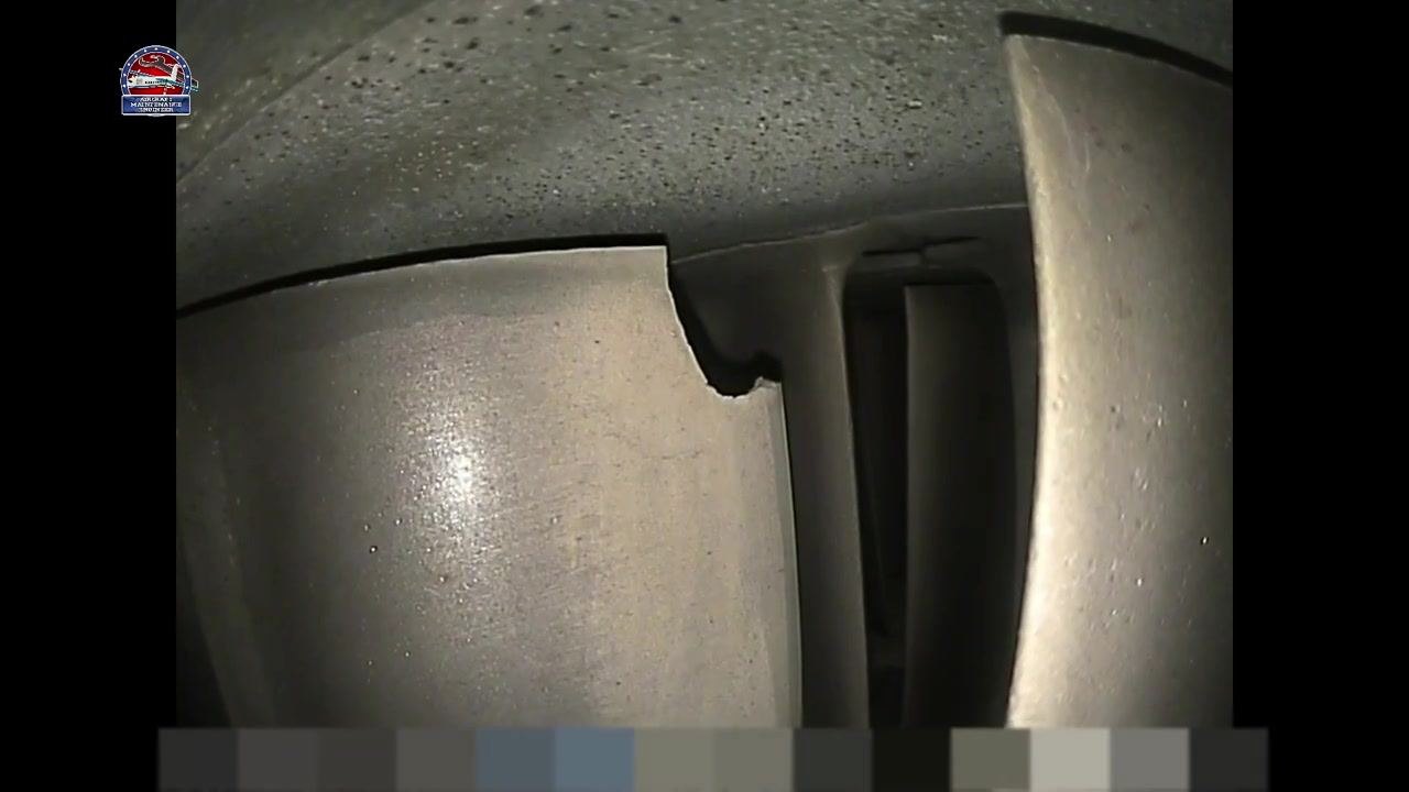
Confirm damage consistency
- Keep the camera steady so the defect remains clearly visible.
- Confirm the damage is consistent across multiple frames, indicating a significant and persistent defect.
-
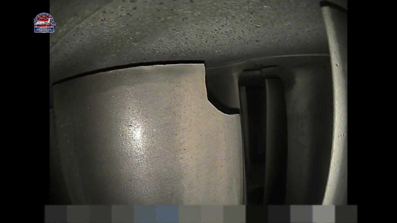
Adjust the angle for an additional perspective
- Slightly shift the camera to view the damaged area from a different angle.
- Note that the depth and width of the missing section are more apparent from this position.
- Ensure the lighting highlights the contours of the damage for accurate documentation.
-
Inspect the blade from a side angle
- Move the camera to the right to capture the side profile of the damaged blade.
- The missing section, viewed from the side, gives a better understanding of the defect's extent.
- Document this perspective for a comprehensive maintenance report.
-
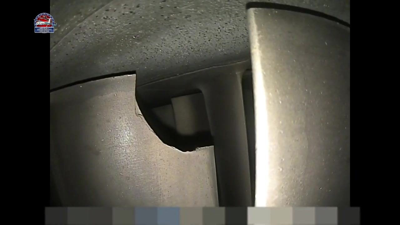
Capture the full extent of the damage
- Continue moving the camera to reveal the entire damaged area.
- The missing section appears even larger and more severe from this angle.
- Include this view in the inspection documentation to support urgent maintenance action.
-
Confirm the next blade is intact
- Move the camera past the damaged blade to inspect the next one in the sequence.
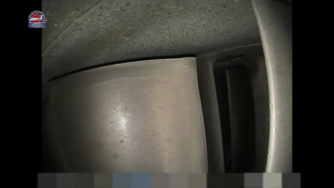
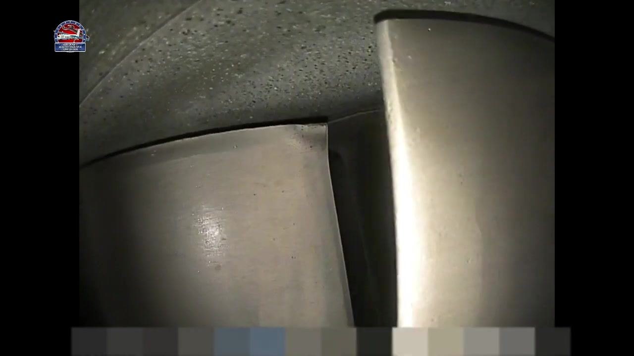
- The next blade appears intact, with a smooth surface and no visible chips or cracks.
-
Continue inspecting adjacent intact blades
- Shift the camera further to inspect another adjacent blade.
- The blade surface remains smooth, with no visible defects or irregularities.
- Document the absence of damage for maintenance records.
-
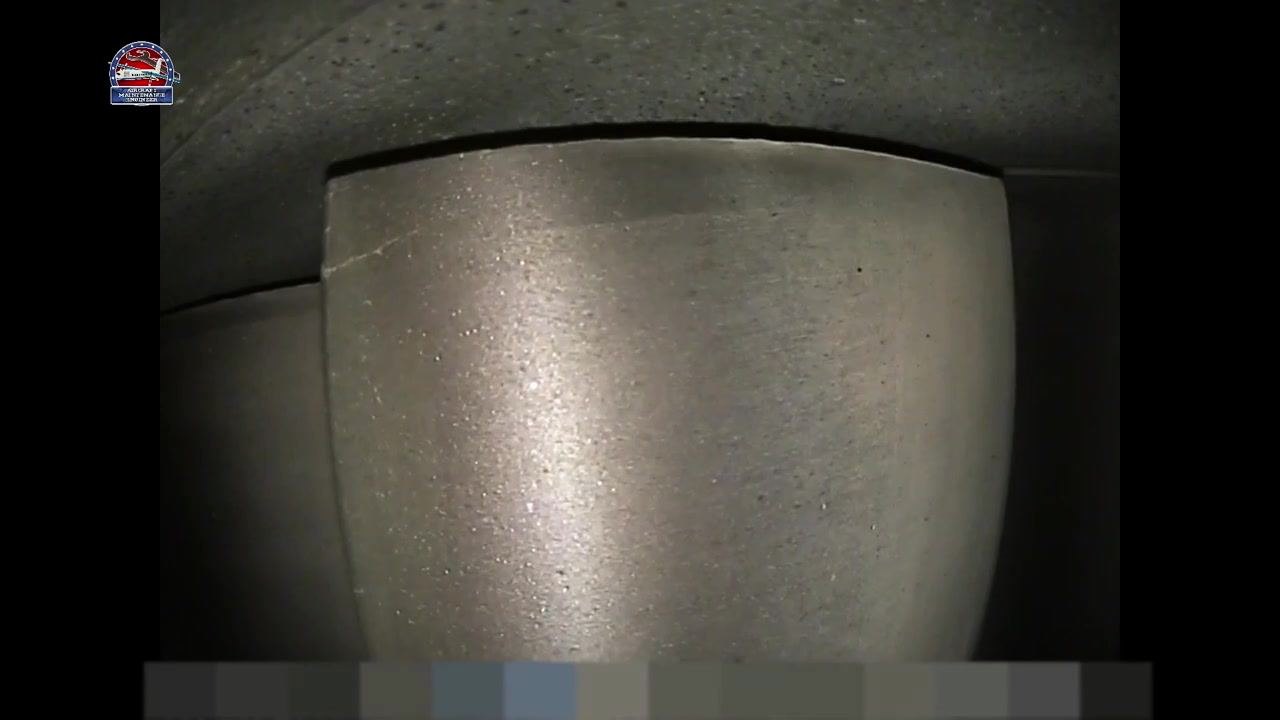
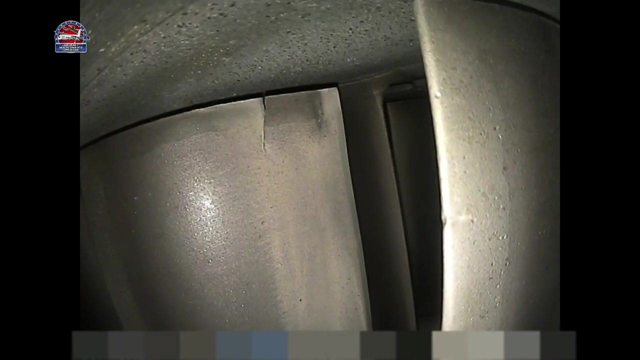
Identify minor surface cracks on the next blade
- Move the camera to focus on the top edge of the next blade.
- A small surface crack or indentation is visible near the top edge.
- Document the location and size of the crack for further evaluation.
-
Revisit the previously damaged blade to confirm findings
- Return the camera to the previously damaged blade to confirm the defect.
- The large, irregular chip or missing section is still visible, confirming the severity of the damage.
- Ensure all documentation is complete and clear before moving to maintenance action.
Part 2: Continue surface inspection across remaining blades
-
Inspect the next set of blades for surface condition
- Position the camera to focus on the next set of turbine blades.
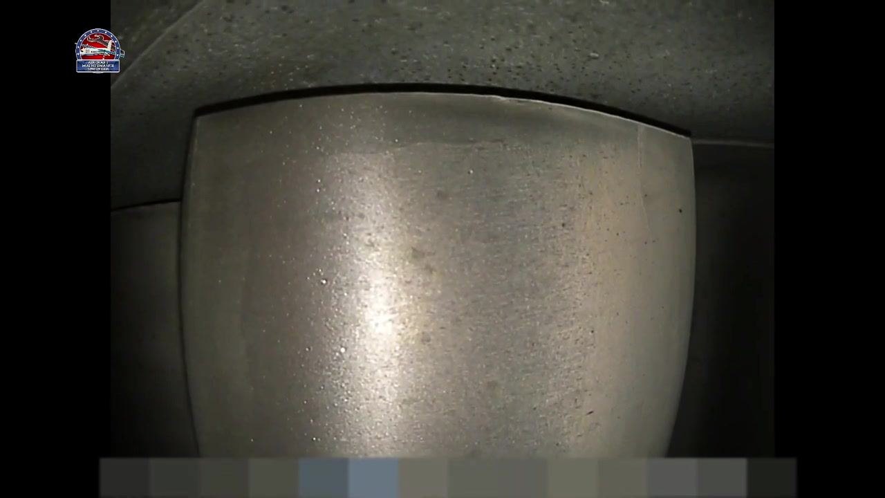
- Two adjacent blades show smooth, metallic surfaces with minor speckling but no cracks, chips, or major defects.
-
Confirm the absence of defects with a steady camera
- Keep the camera steady on the same set of blades to confirm the absence of defects.
- Verify that both blades remain free of cracks, chips, or irregularities across multiple frames.
- Document the clean condition for maintenance records.
-
Confirm blade integrity from a different angle
- Slightly adjust the camera angle to re-examine the same blades.
- The lighting continues to reveal a smooth, undamaged surface, with no new defects visible.
-
Shift the camera to inspect additional blades
- Move the camera to the right to bring a new blade into view.
- Check the surface of the new blade for cracks, chips, or surface irregularities.
- The blade appears smooth, with no significant defects visible.
-
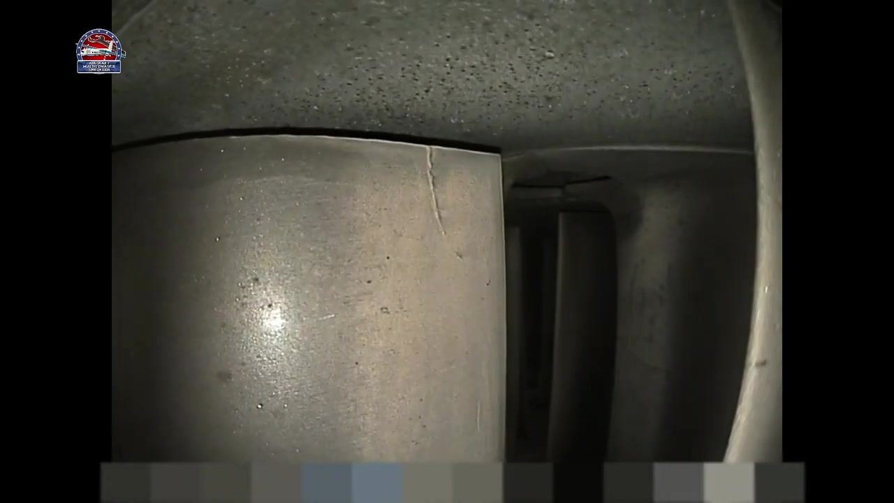
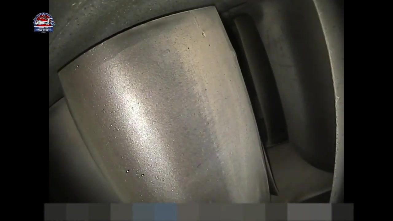
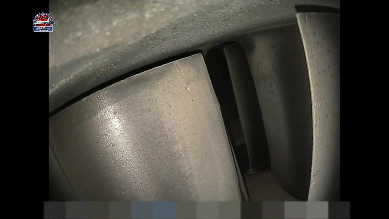
Identify and document a minor surface crack
- Focus the camera on the top edge of the blade now centered in the frame.
- A small, visible surface crack or indentation is present near the top edge.
- Document the precise location and appearance of the crack for further evaluation and maintenance planning.
-
Confirm the crack from a wider angle
- Pull the camera back slightly to capture a wider view of the blade with the crack.
- Confirm the crack remains visible and is clearly documented.
- Note the relative position of the crack to adjacent blades.
-
Re-examine previous blades for consistency
- Move the camera back to the previously inspected blades to confirm their condition.
- Verify that the surfaces remain smooth and free of defects.
- Document the continued absence of damage for maintenance records.
-
Inspect for surface discoloration or deposits
- Focus the camera on a blade with visible surface discoloration or minor deposits.
- Dark spots or stains are present on the blade surface, but no structural damage is evident.
- Record the location and extent of the discoloration for cleaning or further analysis.
-
Capture a wide-angle view of multiple blades
- Pull the camera back to provide a wide-angle view of several turbine blades.
- Most blades appear smooth, with minor surface speckling but no significant damage.
- Include this comprehensive view in the inspection documentation for reference.
-
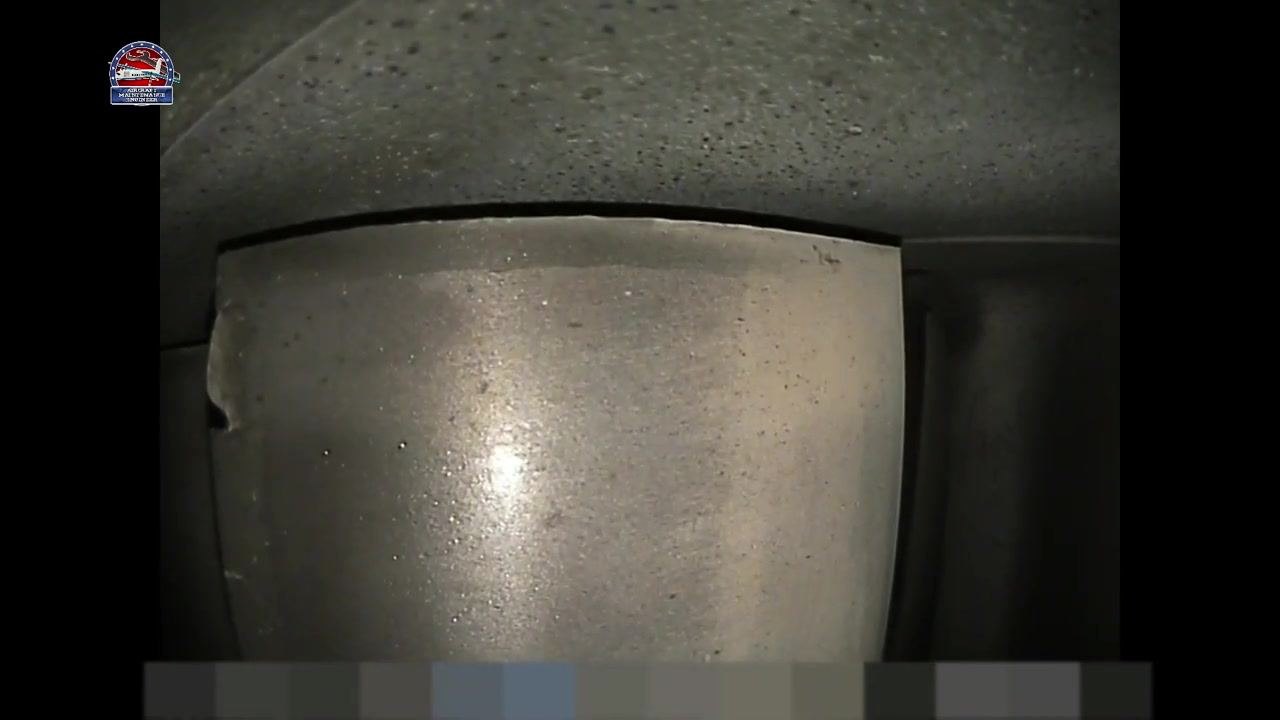
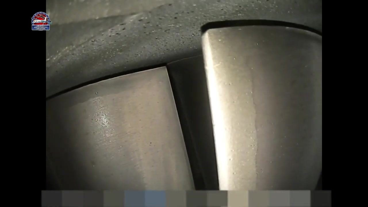
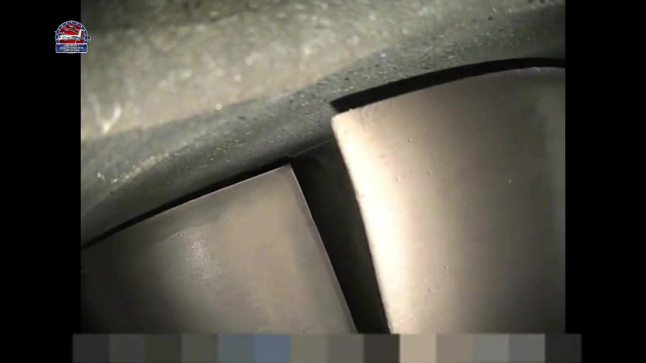
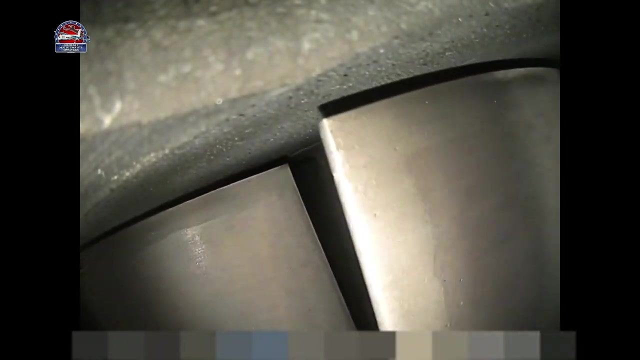
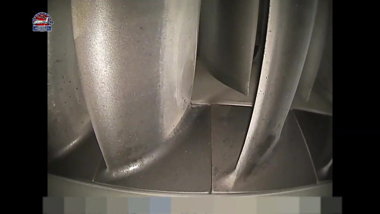
Inspect the blade root and platform area closely
- Position the camera to focus closely on the root and platform area of the turbine blades.
- The surfaces appear smooth and metallic, with minor specks but no visible cracks, chips, or major defects.
- Lighting directed at the platform provides clear visibility of the area.
- Examine the blade root and platform for any signs of wear, pitting, or structural issues.
- Document the clean condition and any minor marks for maintenance records.
Part 3: Inspect internal turbine or compressor blades with the borescope
-
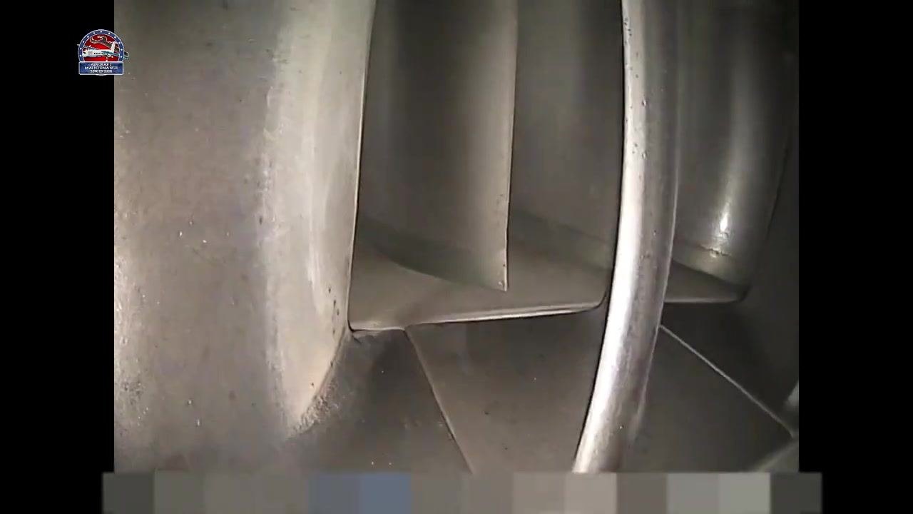
Insert the borescope into the inspection port
- Insert the inspection camera or borescope into the inspection port of the turbine or compressor.
- Orient the camera to provide a clear, close-up view of the blade surfaces.
-
Begin inspecting the first internal blade surface
- Observe the first visible blade surface for signs of wear, pitting, corrosion, or foreign object damage.
- Note the overall surface texture and cleanliness.
-
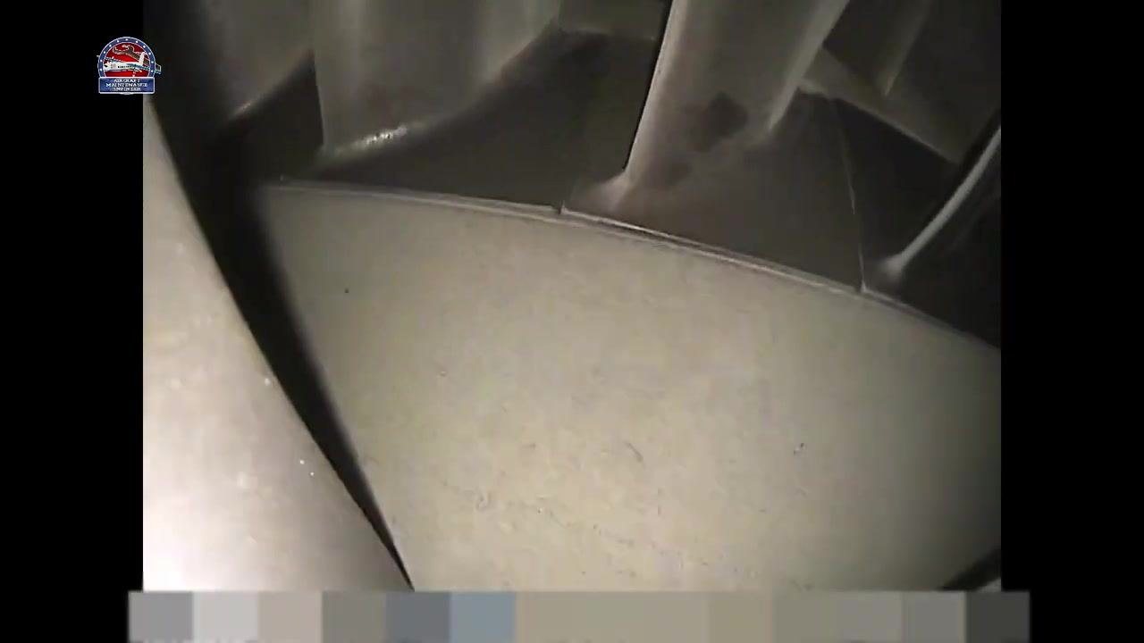
Adjust the camera angle for a broader view of the blade base
- Slowly rotate or tilt the camera to reveal the base and root area of the blades.
- Inspect the junction between the blade and the disk for cracks, discoloration, or debris.
-
Continue systematic inspection of adjacent blades
- Progressively move the camera to inspect adjacent blades, ensuring each blade's surface and root are clearly visible.
- Look for uniformity in blade appearance and check for any anomalies.
-
Repeat the inspection for all remaining blades
- Continue rotating or advancing the camera to inspect each blade in sequence.
- Maintain focus on both the leading and trailing edges of the blades.
-
Document any irregularities found
- If pitting, cracks, or discoloration is observed, pause and capture detailed images for documentation.
- Ensure all areas of interest are well-lit and in focus.
-
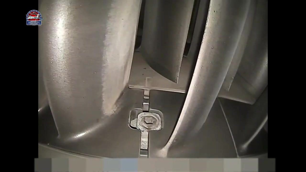
Inspect fasteners and special features at the blade base
- As the camera advances, look for fasteners, locking mechanisms, or unique features at the base of the blades.
- A metallic fastener or locking mechanism visible at the base indicates a structural or assembly feature.
-
Withdraw the camera once this pass is complete
- Once all blades and relevant features have been inspected, slowly withdraw the camera, ensuring no areas are missed.
- Review captured images or video for any overlooked details.
Part 4: Document staining, deposits, and fasteners
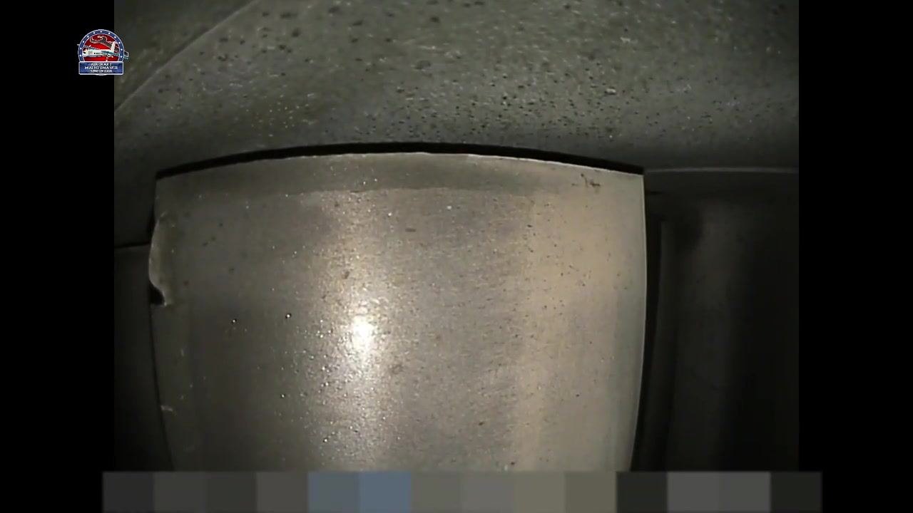
- Inspect blade surfaces for localized staining or deposits
- Closely examine the visible blade surfaces for any localized discoloration, staining, or deposits.
- Darkened spots or patches on the lower portion of the blade may indicate minor staining or residue.
- Keep the camera steady and ensure the lighting is sufficient to clearly observe these surface features.

- Widen the field of view to assess multiple blades
- Adjust the camera position to provide a broader view, capturing several adjacent blades and their bases.
- Continue checking for uniformity in blade appearance, wear, pitting, or surface irregularities.
- Confirm that the base of each blade is securely seated and free from visible cracks or damage.
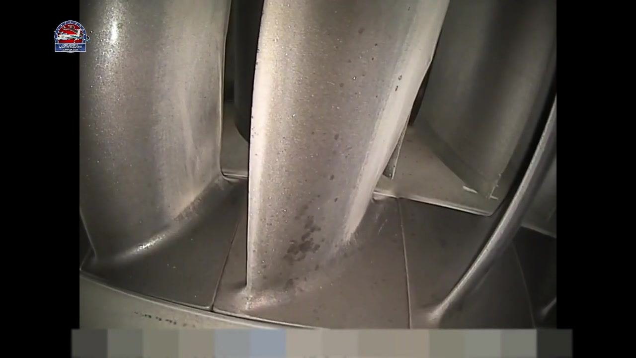
- Identify and inspect fasteners or locking mechanisms between blades
- Move the camera to focus on the area between the blades at their base.
- Identify any fasteners, locking mechanisms, or unique assembly features present.
- Carefully inspect the fastener for signs of wear, corrosion, or improper installation.
- Document the condition of the fastener with a clear image if any irregularities are observed.
- Complete the inspection and withdraw the camera
- Once all blades and fasteners have been inspected, slowly withdraw the inspection camera from the port.
- Ensure that no areas have been missed and that all relevant features have been documented.
- Review all captured images or video for completeness and clarity.
Post-inspection review and reporting
-
Review captured media
- Examine all images and video recorded during the inspection for any overlooked defects or features.
- Organize and label images, especially those showing irregularities or special features.
-
Prepare the inspection report
- Document all findings, including the condition of blade surfaces, bases, and fasteners.
- Note any areas requiring further investigation or maintenance.
-
Proceed to the next maintenance steps
- If no issues are found, proceed with reassembly or the next scheduled maintenance task.
- If defects are identified, follow your organization's procedures for reporting and corrective action.
Verification and summary
- Always document the location and extent of any cracks, chips, or surface defects found during the inspection.
- Use multiple camera angles to confirm and record each defect before closing out the inspection.
- Prioritize urgent maintenance for components with severe damage, such as large chips or long cracks.
- Record both the presence and absence of defects for every blade inspected.
- Combine close-up and wide-angle views to ensure comprehensive documentation of blade condition.
- Inspect blade roots, platforms, and fasteners for wear, pitting, corrosion, or improper installation.
- Maintain steady, well-lit camera positioning throughout to support accurate inspection records.
- Review all captured media and complete the inspection report before proceeding to reassembly or corrective action.
What's next
Once the inspection report is complete, follow your organization's maintenance protocol: proceed with reassembly or the next scheduled maintenance task if no issues were found, or follow your reporting and corrective action procedures if defects were identified during the inspection.
Generation details: cost, quality tiers
Docsie billed 4,000 credits ($2.80) to analyze this 8-minute video at standard quality. The rewrite, template fill and Word/PDF exports were included. The same video at each quality tier:
| Quality | Frames sampled | Credits | Approx. cost |
|---|---|---|---|
| Draft | every 16-30 s | 2,000 | $1.40 |
| Standard (this guide) | every 8-15 s | 4,000 | $2.80 |
| Detailed | every 4-7 s | 8,000 | $5.60 |
| Ultra | every 1-3 s | 16,000 | $11.20 |
Credits priced at $0.70 per 1,000; plans include a monthly allowance. Enterprise customers on on-premise or bring-your-own-model deployments run this on their own inference and pay no per-video credits.
Generated by Docsie Video-to-Docs on 2026-09-14 from a 7-minute video. Screenshots are frames from the source video and belong to their creator, Aircraft Maintenance Engineer, whose original is embedded above. If you own this video and want the guide removed or credited differently, contact us and we will act within one business day.