
How to Create a Control Plan
A control plan is the reference document that ties every manufacturing step to its inspection method, sampling rule, and reaction plan. This guide walks through how to create a control plan for an electronic product assembly line, following the manufacturing flow from incoming goods inspection through pre-assembly, final assembly, packing, and outgoing inspection. Use it as a reference when building or reviewing a control plan for your own assembly process.
Video: Process Control Plan Example: Electronic Product (Walkthrough) | CMC by China Manufacturing Consultants (2020). All credit for the demonstration goes to the creator; watch the original on YouTube. The written guide below was generated from this video by Docsie. Creator? Request a change or removal.
A control plan is the reference document that ties every manufacturing step to its inspection method, sampling rule, and reaction plan. This guide walks through how to create a control plan for an electronic product assembly line, following the manufacturing flow from incoming goods inspection through pre-assembly, final assembly, packing, and outgoing inspection. Use it as a reference when building or reviewing a control plan for your own assembly process.
Prerequisites
Before you build the control plan, have the following ready:
- Product specifications for each critical component (battery, PCBA, motor, etc.)
- A list of equipment and tools used at each process step
- Applicable sampling standards (for example, AQL tables)
- Inspection record forms: IQC report, first piece inspection record, inline inspection record, PQC inspection record, and OQC inspection record
Header
The control plan header identifies the plant, customer, program, part number, revision level, plan type, and approval status. The source material for this guide shows only the revision-level fields (revision "A1," authored by AlexChen, dated Dec. 17, 2019, with a description of changes). Plant, customer, program name, part number, plan type, and approval status are not shown and must be filled in with your project's actual details when you create the plan.
Process flow
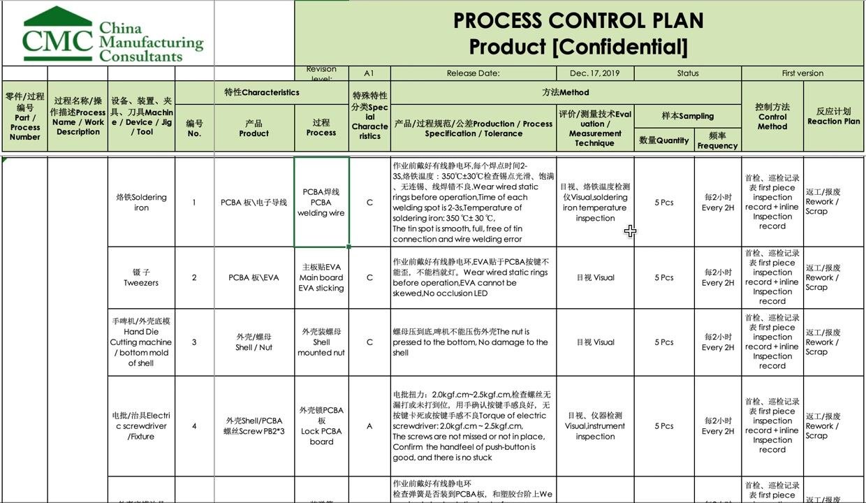
Start by reviewing the overall structure of the control plan. Each row corresponds to a specific process step and is organized by process step, characteristic, method, sampling, and control/reaction plan. The columns typically include process number, description, equipment/tool, product, process, special characteristics, production specification/tolerance, evaluation/measurement technique, sampling quantity, frequency, control method, and reaction plan.
The assembly flow covered in this example includes the following operations, in sequence:
| Operation | Process name | Equipment/tool | Linked PFMEA row |
|---|---|---|---|
| 1 | Incoming goods inspection | Manual visual check, multimeter, comprehensive tester, calipers | Not specified in source |
| 2 | Soldering on PCBA | Soldering iron | Not specified in source |
| 3 | Main board EVA sticking | Tweezers | Not specified in source |
| 4 | Shell/nut mounting | Hand die cutting machine / bottom mold of shell | Not specified in source |
| 5 | Lock PCBA board | Electric screwdriver/fixture | Not specified in source |
| 6 | Pre-final assembly sub-assembly check | Manual comparison against reference samples | Not specified in source |
| 7 | Semi-finished product inspection | Visual and instrument inspection | Not specified in source |
| 8 | Glue application | Glue equipment (air pressure/speed control) | Not specified in source |
| 9 | Battery cover assembly | Electric screwdriver | Not specified in source |
| 10 | Finished product inspection | Visual and functional check, air gun | Not specified in source |
| 11 | Packing | Blister box, color box | Not specified in source |
| 12 | Outgoing inspection | Random sampling per checklist | Not specified in source |
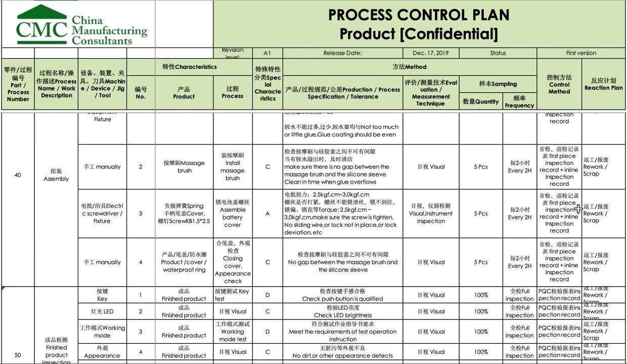
Before starting final assembly, stop the line and check key sub-assemblies. For example, test the push-button for correct hand feel by comparing it against a known good sample, and, where available, reference samples that are too hard or too soft.
During packing, the flow moves from final inspection into packing steps, covering appearance inspection, blister box/battery placement, cleaning, and folding of the color box.
Product characteristics
The following characteristics are checked at incoming inspection and carried through the control plan. Special characteristics are classified using letters:
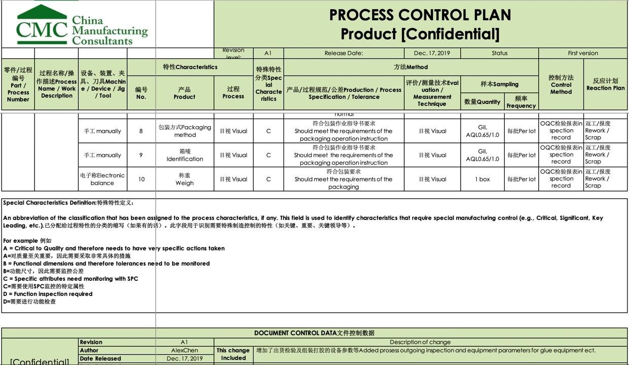
- A – Critical to quality, requiring very specific actions
- B – Functional dimension that needs monitoring
- C – Attribute requiring monitoring with Statistical Process Control (SPC)
- D – Function inspection required
| Characteristic | Specification/tolerance | Classification | Measurement method |
|---|---|---|---|
| General appearance | No dirt, shrinkage, or glue shortage | Not specified | Manual visual inspection |
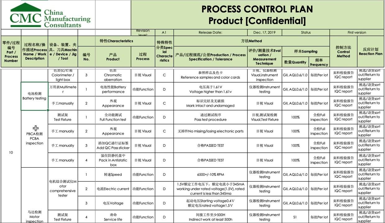
| Battery voltage | Higher than 1.61V | Not specified | Multimeter (instrument testing) |
| Battery appearance | Mark intact and undamaged | Not specified | Visual |
| PCBA parts | No missing or losing electronic parts | Not specified | Visual (100% inspection) |
| PCBA QC pass sticker | Passed test | Not specified | Visual (100% inspection) |
| PCBA packaging | Packed in antistatic box | Not specified | Visual (100% inspection) |
| Motor speed | 6500 ± 10% RPM | Not specified | Instrument testing |
| Motor current | 1.5V working voltage, current < 345mA | Not specified | Instrument testing |
| Motor voltage | Starting voltage 0.4V, rated voltage 1.5V | Not specified | Instrument testing |
| Motor service life | At least 500h | Not specified | Instrument testing |
| Motor noise | < 60dB under rated voltage | Not specified | Instrument testing |
| Motor size | 30 × 15.2 × 11.8 mm | Not specified | Calipers |
| Motor appearance | No oxidation/dirt, mark intact | Not specified | Visual |
| Battery cover screw | Tightened, no sliding wire, lock not deviated | A/D (special characteristic) | Visual, instrument (torque) |
Process characteristics
Process-level parameters are set for each pre-assembly and assembly operation, with defined limits and inspection frequency.
| Process parameter | Target setting | Limit | Monitoring frequency | Responsible role |
|---|---|---|---|---|
| Soldering iron temperature | 350°C | ± 30°C | 5 pieces every 2 hours | Line leader or quality inspector |
| Welding spot time | 2–3 seconds | N/A | 5 pieces every 2 hours | Line leader or quality inspector |
| Main board EVA sticking | No skew, no LED occlusion | N/A | 5 pieces every 2 hours | Line leader or quality inspector |
| Shell/nut mounting | Nut pressed to bottom, no shell damage | N/A | 5 pieces every 2 hours | Line leader or quality inspector |
| PCBA screw torque | 2.0–2.5 kgf.cm | No damage to screw or PCBA | 5 pieces every 2 hours | Line leader or quality inspector |
| Glue application (setting 1) | Air pressure 0.15–0.2 MPa | Speed 20–25 | 5 pieces every 2 hours | Line leader or quality inspector |
| Glue application (setting 2) | Air pressure 0.18–0.25 MPa | Speed 26–30 | 5 pieces every 2 hours | Line leader or quality inspector |
| Glue application (setting 3) | Air pressure 0.22–0.35 MPa | Speed 31–35 | 5 pieces every 2 hours | Line leader or quality inspector |
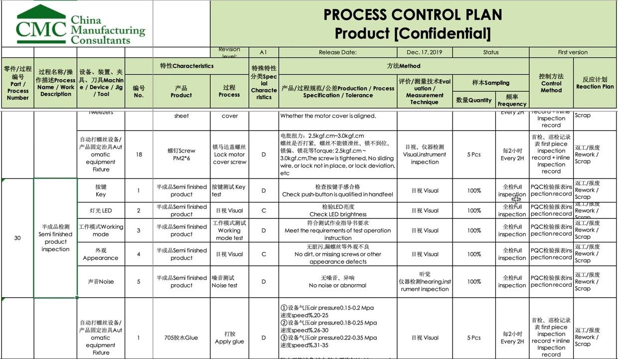
| Battery cover screw torque | 2.5–3.0 kgf.cm | No sliding wire, lock deviation | 5 pieces every 2 hours | Line leader or quality inspector |
Operators must wear static rings before soldering and EVA sticking operations. Torque values and known failure modes (missed screws, non-functioning push-button, stuck parts) should be included in operator work instructions so that operators understand the process specifications and inspection criteria they are working to.
Methods
Inspections use a mix of visual checks, instrument testing, and full or sampled inspection, depending on the process step.
- Incoming goods: Sampling GII, AQL 0.6/1.0, each lot; method is manual visual inspection or instrument testing (multimeter, comprehensive tester, calipers); results recorded in the IQC report.
- PCBA inspection: 100% full inspection; visual method; results recorded in the IQC report.
- Pre-assembly and assembly steps (soldering, EVA sticking, shell/nut mounting, PCBA locking, glue application, battery cover assembly): Sample 5 pieces every 2 hours; visual or instrument method; results recorded in the first piece inspection record and inline inspection record.
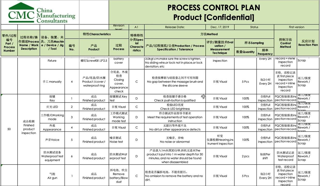
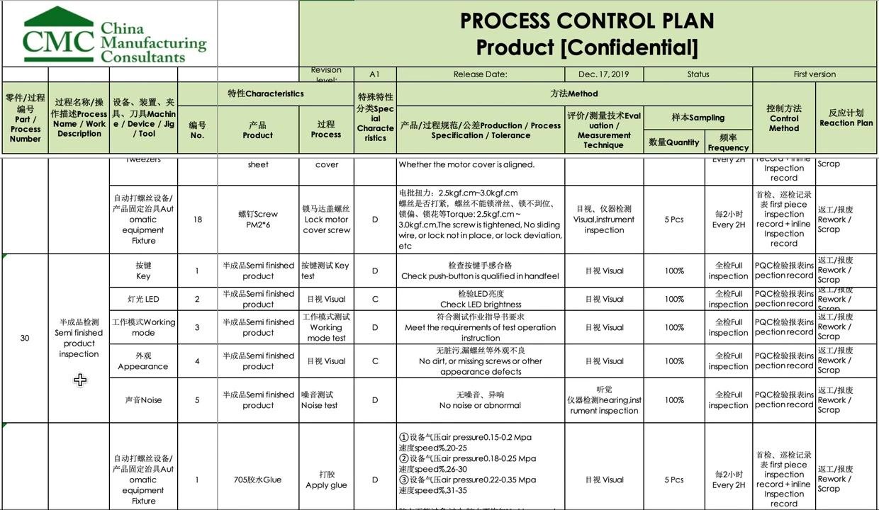
- Semi-finished product inspection: 100% full inspection covering key test, LED test, working mode test, appearance, and noise test; results recorded in the PQC inspection record.
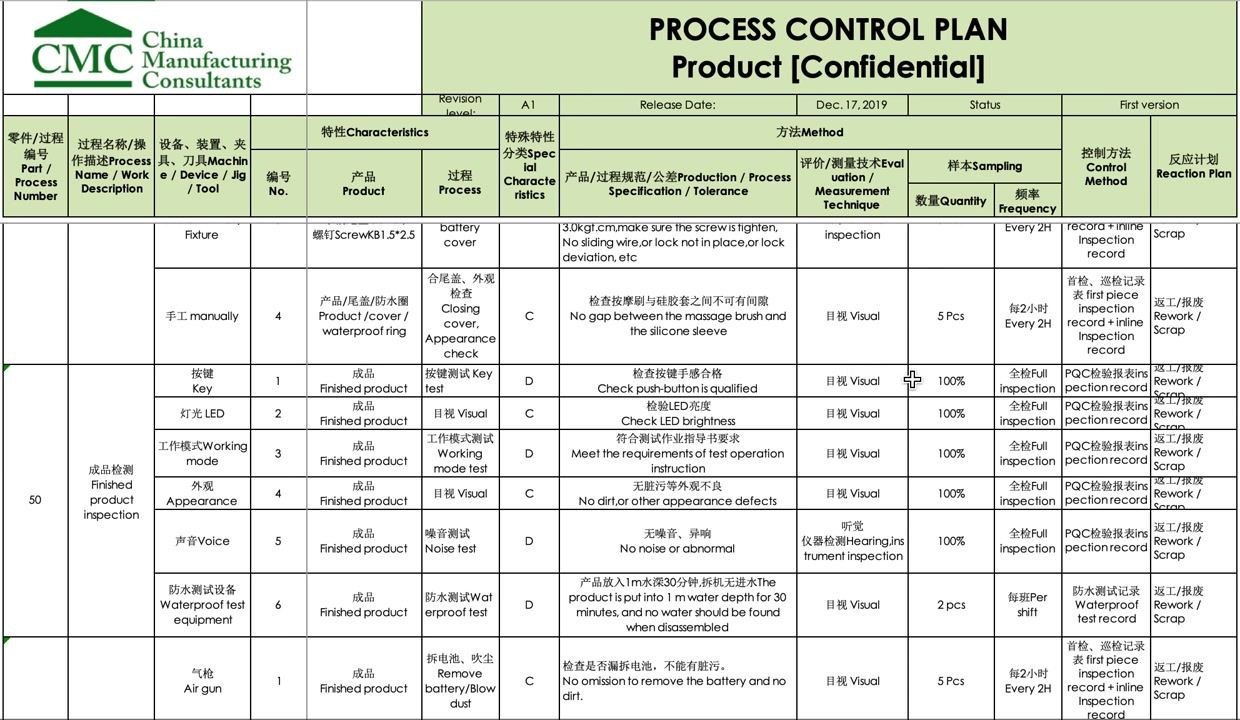
- Finished product inspection: 100% inspection by a dedicated inspector, covering key test, LED brightness, working mode, appearance, noise, waterproofing, and removal of battery/dust; results recorded in the PQC inspection record.
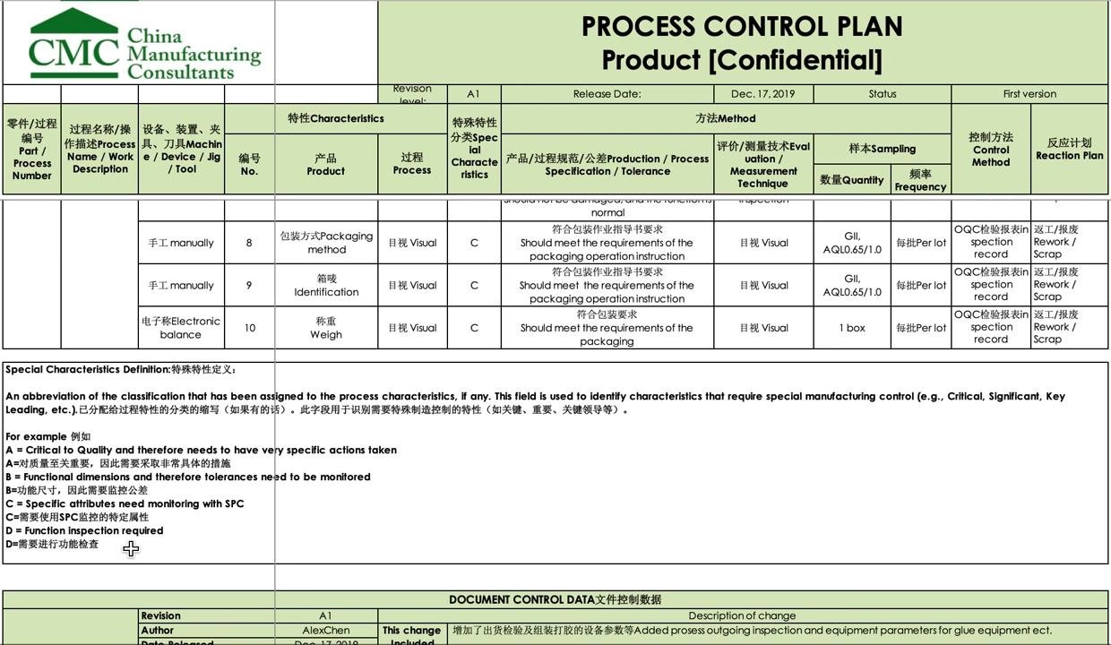
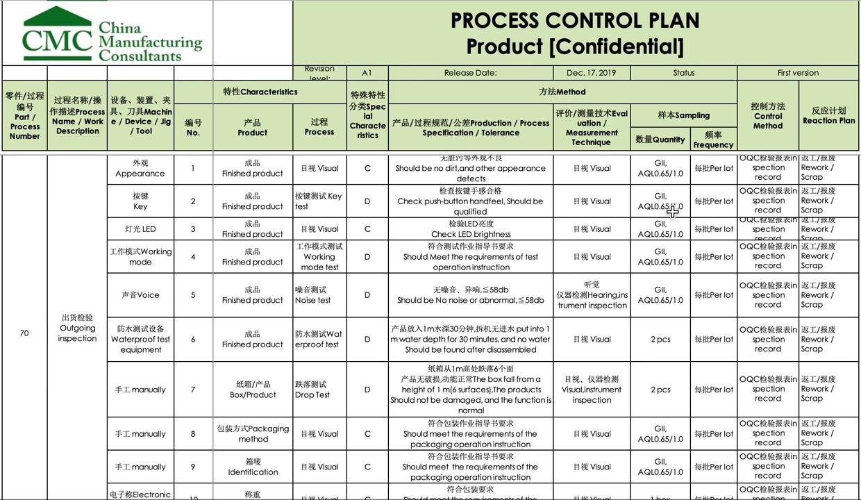
- Outgoing inspection: Random sampling, GII, AQL 0.65/1.0, 2 pieces per lot for product checks and 1 box per lot for packaging; results recorded in the OQC inspection record.
Calibration requirements for gauges and instruments (multimeter, comprehensive tester, calipers) are not detailed in the source material and should be defined separately in your gauge management procedure.
During packing, additional checks are performed: inspect the appearance of the finished product for cleanliness, confirm the blister box and batteries are free from damage and foreign matter, clean the product surface with an air gun, and inspect the color box for damage, dirt, or dust before sealing.
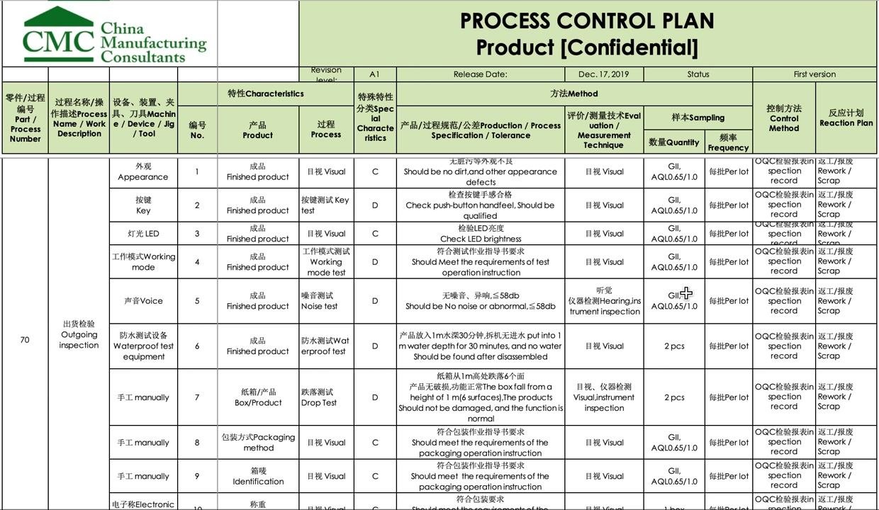
Outgoing inspection goes beyond the 100% in-line checks, applying random sampling for a deeper review of appearance, key function, LED brightness, working mode, noise, waterproofing, drop test, packaging method, identification, and weight.
The outgoing inspection checklist specifies exact criteria for each attribute, such as "no dirt or other appearance defects," "check push-button hand feel," "LED brightness," "no noise or abnormal noise, ≤ 58dB," "waterproof test for 30 minutes," and "drop test from 1m," along with the applicable sampling quantity and frequency.
Reaction plan
The reaction plan defines what happens when a check fails at any stage.
- Immediate containment: For incoming goods, sort out the non-conforming item and return it to the supplier. For in-process defects (soldering, EVA sticking, shell/nut mounting, PCBA locking, glue application, battery cover assembly), rework or scrap the item.
- Escalation: Inspections are performed by the production line leader or by an external inspector from the quality department; either role can raise a non-conformity for action.
- Disposition: Place defective finished products in a designated red box (or similar container) so they are not mixed with conforming products, pending rework or scrap decision.
- Restart criteria: Perform a first piece inspection immediately after starting assembly. If problems are found, stop and correct them before continuing mass production. Routine in-process inspection of 5 pieces every 2 hours then continues for all critical assembly steps.
Special characteristics marked "A" or "D" are treated as critical to product quality — for example, the battery cover screw torque — and any deviation follows the same rework-or-scrap reaction path documented in the first piece inspection record and inline inspection record.
Revision history
Document control ensures only the latest, approved version of the control plan is used in production and inspection, and it provides traceability for changes.
| Revision | Reason for change | Approver | Effective date |
|---|---|---|---|
| A1 | Added process for outgoing inspection and equipment parameters for glue equipment, etc. | AlexChen | Dec. 17, 2019 |
Keep documents stored securely and organized to prevent loss or unauthorized changes, and review them regularly as processes or requirements change. Always refer to the current version of the control plan and its associated checklists during operations.
What's next
Once your control plan is drafted, link each process row to its corresponding PFMEA entry, confirm gauge calibration schedules with your quality team, and train operators and inspectors on the sampling frequency and reaction plan for each step before releasing the plan for production use.
Generation details: cost, quality tiers, downloads
Docsie billed 3,500 credits ($2.45) to analyze this 7-minute video at standard quality. The rewrite, template fill and Word/PDF exports were included. The same video at each quality tier:
| Quality | Frames sampled | Credits | Approx. cost |
|---|---|---|---|
| Draft | every 16-30 s | 1,750 | $1.22 |
| Standard (this guide) | every 8-15 s | 3,500 | $2.45 |
| Detailed | every 4-7 s | 7,000 | $4.90 |
| Ultra | every 1-3 s | 14,000 | $9.80 |
Credits priced at $0.70 per 1,000; plans include a monthly allowance. Enterprise customers on on-premise or bring-your-own-model deployments run this on their own inference and pay no per-video credits.
Generated by Docsie Video-to-Docs on 2026-09-10 from a 6-minute video. It was generated straight into Docsie's Control Plan template, so every section of that template is filled from the video. Screenshots are frames from the source video and belong to their creator, China Manufacturing Consultants, whose original is embedded above. If you own this video and want the guide removed or credited differently, contact us and we will act within one business day.