
How to PLC How to Program
This SOP explains, step by step, PLC how to program a Delta DVP-series controller for a Direct-On-Line (DOL) dual starter application. You will see how the electrical panel is wired, how the input and output devices are connected to the PLC, and how to build, compile, download, and test a ladder logic program using WPLSoft.
Video: PLC Training : Learn PLC Wiring and Programming from Today @ElectricalTechnician by Electrical Technician (2024). All credit for the demonstration goes to the creator; watch the original on YouTube. The written guide below was generated from this video by Docsie. Creator? Request a change or removal.
This SOP explains, step by step, PLC how to program a Delta DVP-series controller for a Direct-On-Line (DOL) dual starter application. You will see how the electrical panel is wired, how the input and output devices are connected to the PLC, and how to build, compile, download, and test a ladder logic program using WPLSoft.
Purpose
This document guides you through the complete process of wiring a Delta PLC panel and writing the ladder logic needed to control a motor with START and STOP push buttons through a contactor. It also shows how to verify your program on a physical training panel.
Scope
This procedure applies to anyone setting up a Delta DVP-12SA (or similar) PLC for a basic dual starter control circuit, using WPLSoft as the programming software. It covers panel wiring, PLC programming, compiling, downloading, and testing.
Required equipment and materials
- Delta DVP-12SA PLC (or compatible Delta DVP model)
- WPLSoft programming software installed on a computer
- 24V DC power supply
- Two MCBs (Miniature Circuit Breakers): one rated for 24V DC, one rated for 230 VAC
- Two push buttons (green Start, red Stop)
- One contactor for motor control
- Red, black, and green wires for +Ve, -Ve, and earth connections
- A PLC training panel with push buttons, indicator lights, and a communication cable (e.g., RS232)
Procedure
1. Review the electrical panel and basic operation
Before wiring or programming, observe the electrical panel connected to the PLC. The panel contains circuit breakers (MCB), a Delta PLC, an HMI screen, push buttons, selector switches, limit switches, a fan, and a stack light with labeled indicators (Y0, Y1, Y2). All wiring is routed and labeled clearly for easy identification.
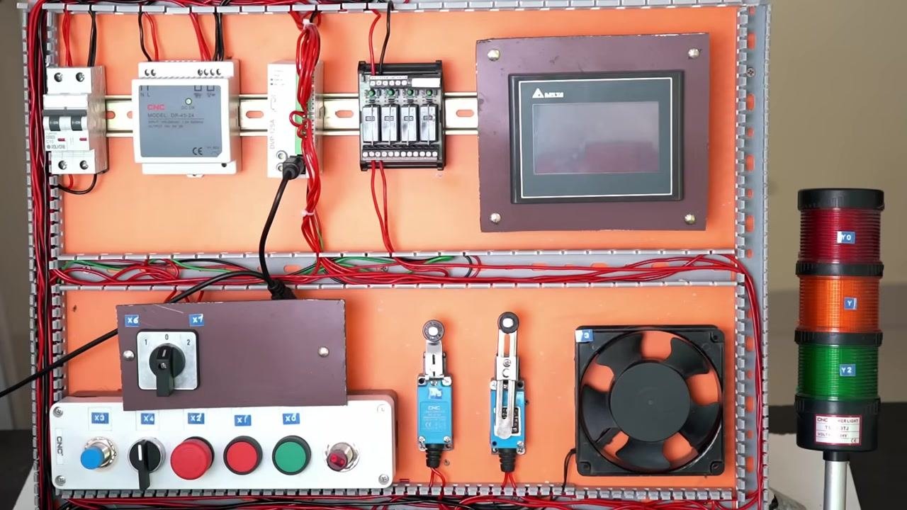
To start the motor, press the green Start push button on the control panel. The control panel includes a rotary selector switch, an emergency stop, red and green push buttons, and indicator lights. The green button is used to start the motor.
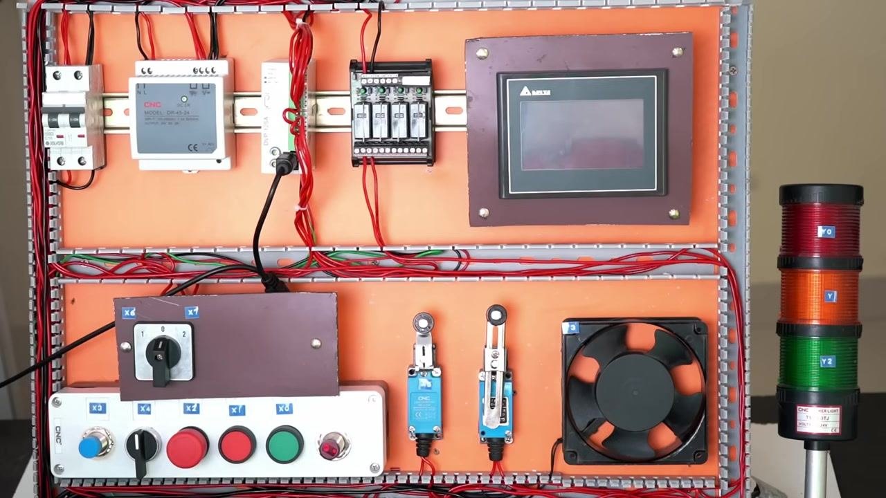
To stop the motor, press the red Stop push button. The red button is used for stopping the motor, and the motor turns off as soon as this button is pressed.
2. Prepare for PLC wiring and programming
This procedure covers both wiring the PLC and programming the steps required to control the motor. The PLC used is a Delta model, and the programming is done using WPLSoft software.
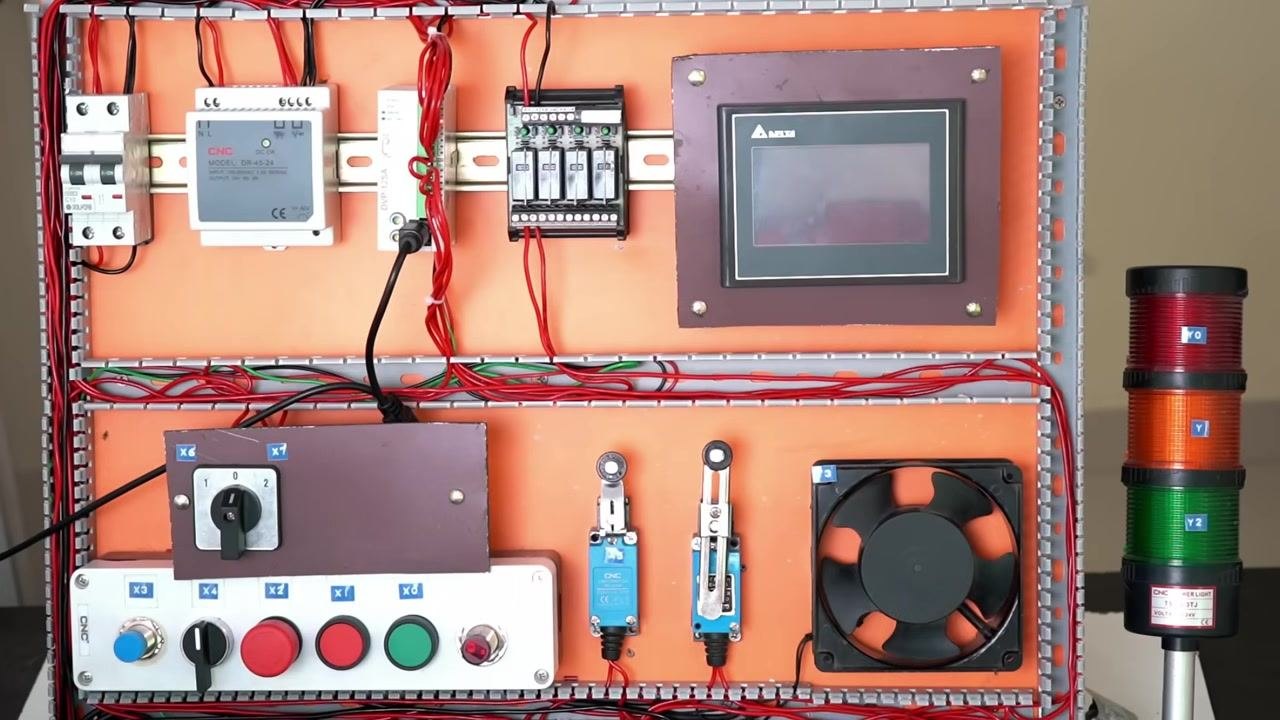
Install and open the WPLSoft programming software for Delta PLCs. Locate and launch the WPLSoft application on your computer. This software is specifically designed for Delta DVP Programmable Logic Controllers.
3. Wire the DC power supply to the PLC
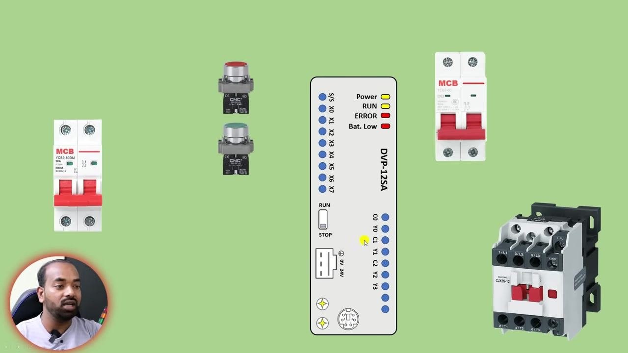
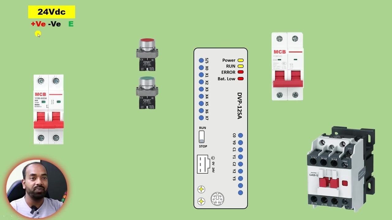
Prepare to provide a DC power supply to the PLC. Use a 24V DC power supply and identify the positive (+Ve), negative (-Ve), and earth (E) terminals. Gather two MCBs, two push buttons (Start and Stop), a Delta DVP-12SA PLC, and a contactor.
Connect the positive and negative power supply wires to the MCB. Use a red wire for +Ve (positive) and a black wire for -Ve (negative). Ensure the MCB is rated for 24V DC and properly installed. Safety note: Confirm the MCB rating matches your supply voltage before energizing the circuit.
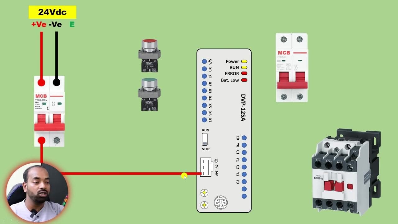
Connect the positive power supply from the MCB to the PLC terminal labeled 24V. Locate the "24V" terminal on the PLC (DVP-12SA) and connect the red wire from the MCB output to it.
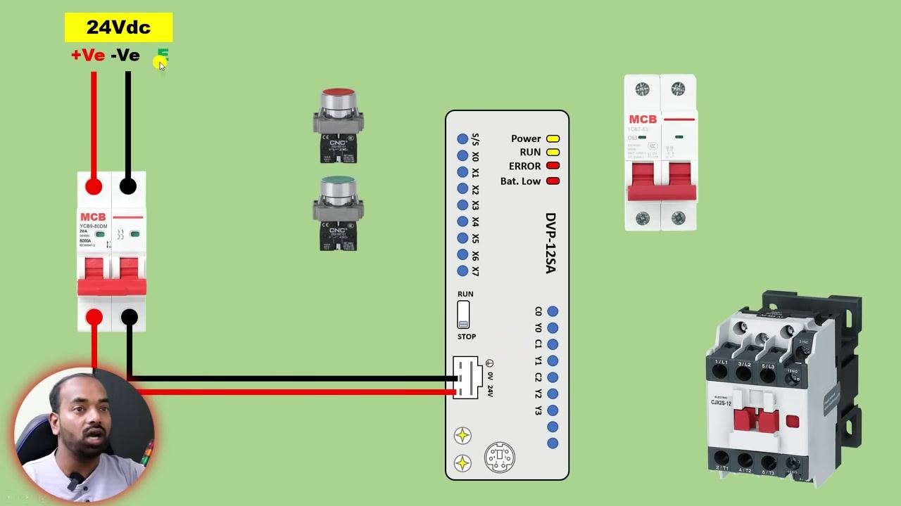
Connect the negative power supply from the MCB to the PLC terminal labeled 0V. Locate the "0V" terminal next to the "24V" terminal on the PLC and connect the black wire from the MCB output to it.
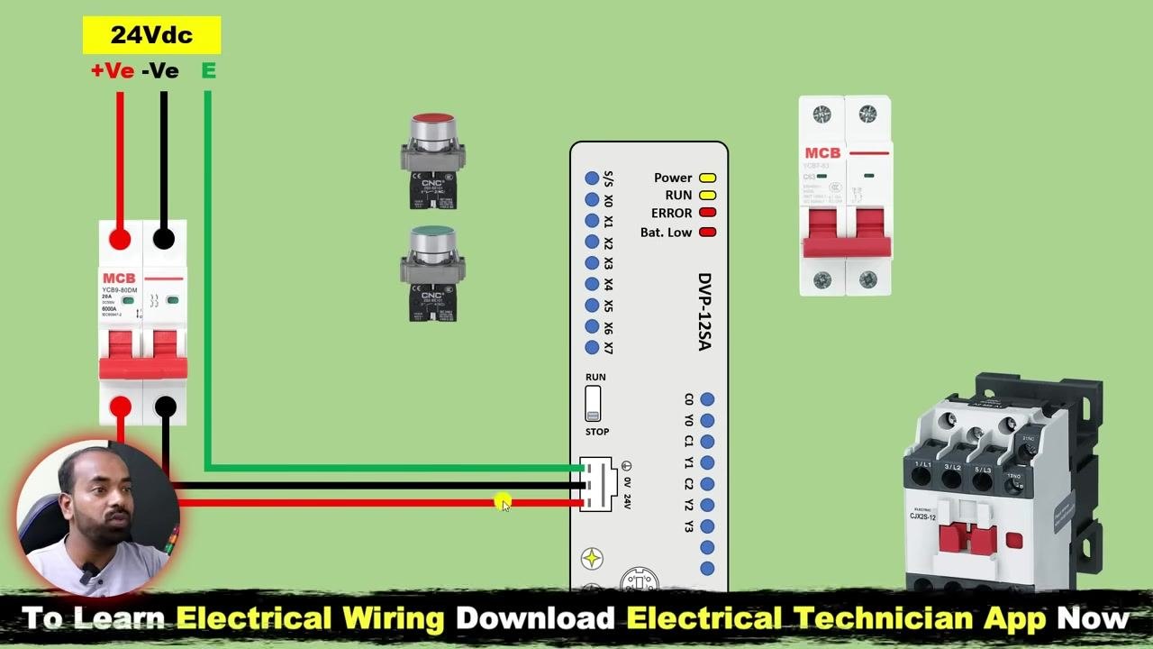
Connect the earth (E) wire to the PLC's ground terminal. Locate the ground symbol on the PLC and connect the green earth wire from the power supply to it.
4. Wire the start and stop push buttons to the PLC inputs
Gather the required components for dual starter wiring: a green Start push button, a red Stop push button, a contactor, a Delta DVP-12SA PLC, a 24V DC power supply, and an MCB. Ensure all components are present and correctly rated.
Understand the control logic before wiring: the Start push button sends a command to the PLC to start the motor via the contactor, and the Stop push button sends a command to stop it. The contactor switches the motor on and off based on the PLC output.
Review the wiring diagram for the dual starter. It shows the connections between the Start and Stop push buttons, the contactor, and the PLC. The control circuit is designed to energize the contactor coil when the Start button is pressed and de-energize it when the Stop button is pressed.
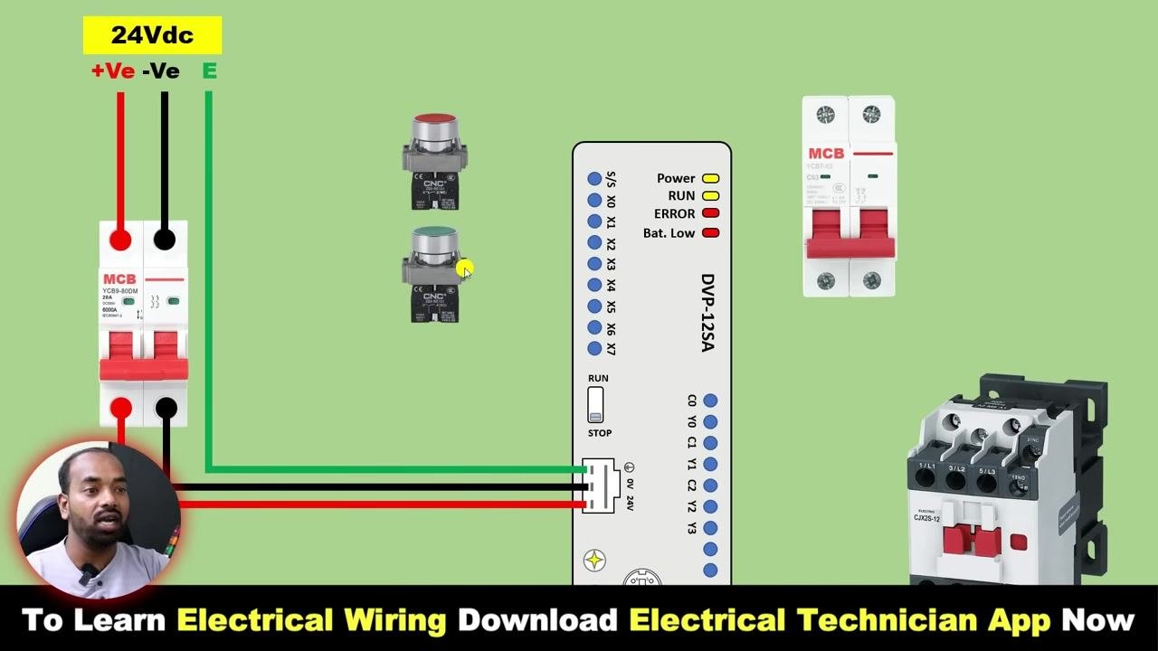
Connect the positive (+Ve) 24V DC power supply to both push buttons. Loop a red wire from the +Ve terminal of the power supply to the common terminal of the Stop push button, then loop another red wire from the Stop push button to the common terminal of the Start push button.
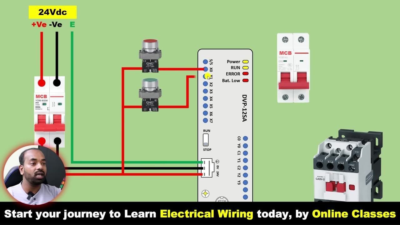
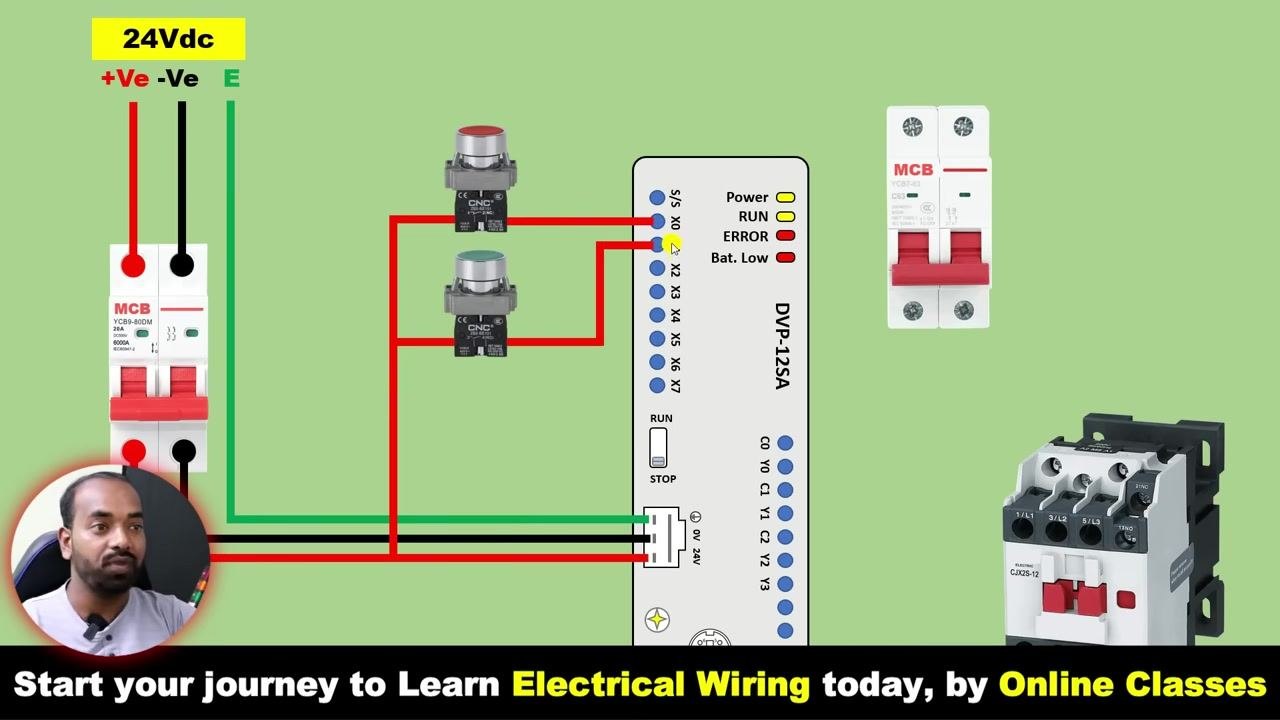
Connect the output of the Stop push button to the PLC input terminal X0. Use a red wire to connect the normally closed (NC) terminal of the Stop push button to the X0 input, allowing the PLC to detect when the Stop button is pressed or released.
Connect the output of the Start push button to the PLC input terminal X1. Use a red wire to connect the normally open (NO) terminal of the Start push button to the X1 input, allowing the PLC to detect when the Start button is pressed.
Ensure the negative (-Ve) power supply is connected to the PLC's source/sink terminal. Use a black wire to connect the -Ve terminal of the power supply to the PLC's S/S (source/sink) terminal. This completes the input circuit for the PLC.
Verify all input power supply connections are complete. Double-check that all wiring matches the diagram, and confirm all connections are secure and terminals properly tightened.
5. Wire the PLC output to the contactor
Connect the negative (-Ve) terminal of the 24V DC power supply to the S/S (Source/Sink) terminal of the PLC. This completes the input power supply circuit for the PLC.
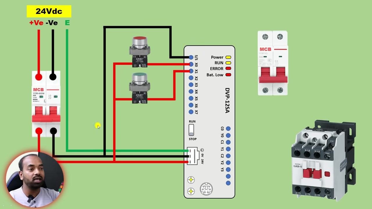
Prepare to connect the contactor for start/stop control. Identify the single-phase MCB for the contactor's power supply and use a single-phase (230 VAC) supply for the contactor, as shown in the diagram. Safety note: If your contactor operates on DC, use a DC power supply instead of AC.
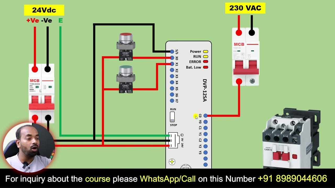
Connect the phase (live) wire from the 230 VAC MCB to the PLC output common terminal (C0). Take a red wire from the phase terminal of the 230 VAC MCB and connect it to the C0 terminal on the PLC.
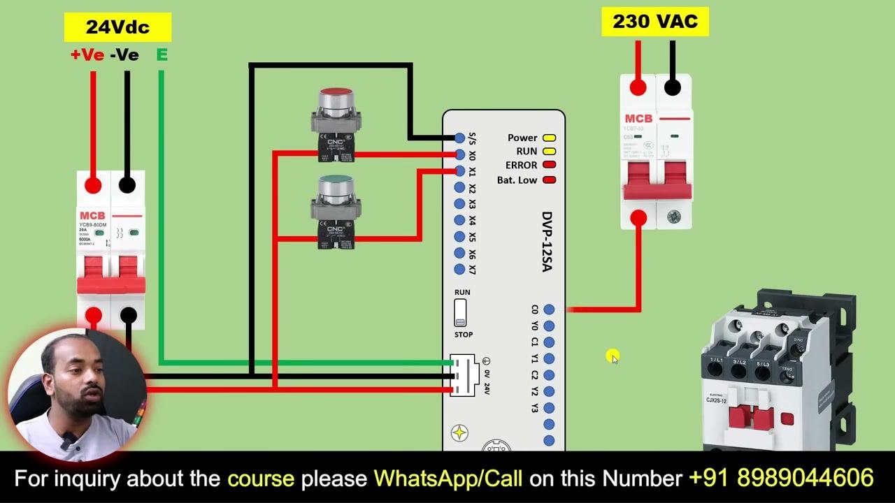
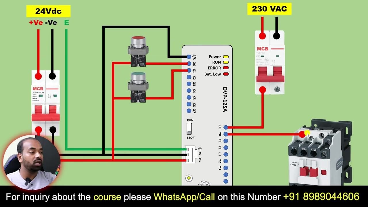
Connect the PLC output (Y0) to the contactor coil terminal (A1). Take a wire from the Y0 output terminal of the PLC and connect it to the A1 terminal of the contactor. This allows the PLC to energize the contactor when the output command is given.
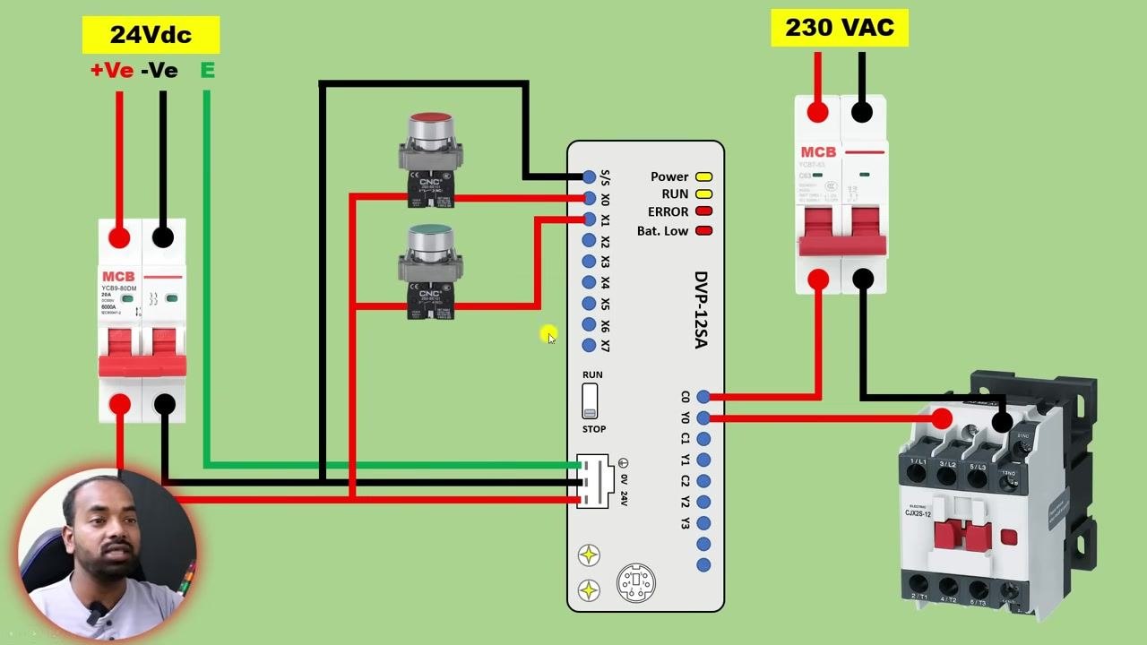
Connect the neutral wire from the 230 VAC MCB directly to the A2 terminal of the contactor. This completes the circuit for the contactor coil.
Double-check all wiring before energizing the panel. Ensure all connections match the wiring diagram, verify that phase and neutral are correctly routed to the contactor and PLC output terminals, and confirm that all terminals are securely tightened with no loose wires.
6. Create a new project in WPL Editor
Open the PLC programming software (WPL Editor or equivalent) and launch it on your computer. The main interface and communication settings will be displayed.
Create a new PLC program by clicking File and selecting New to start a new project. In the "Select a PLC Model" dialog: - Enter the program title as DOL. - Set the Model Type to PLC. - Select the appropriate PLC model (for example, SV2). - Set the Communication Setting to RS232 (COM5), or as required for your hardware. - Enter the file name as DOL. - Click OK to create the new program.
7. Assign the PLC model and open the ladder diagram editor
Open the WPL Editor software on your computer and wait for the main interface to load. The screen displays a blank workspace with a toolbar at the top and a navigation panel on the left.
Select the PLC model for your project. A dialog box titled "Select a PLC Model" appears. Under Model Type, select PLC from the dropdown menu. In the "Select" dropdown you will see options such as PLC, VFD, and TP — choose PLC. Confirm that the "Program Title" and "File Name" fields are set to DOL (or your project name), and ensure "Communication" is set to RS232 (COM5) or as required.
Select the PLC model number. After choosing PLC, a new dropdown appears under "Select" with model numbers such as ES2C, EX, SS, SA, SX, SC, EH, EH2. Choose the model number matching your hardware (for example, SA for DVP-12SA).
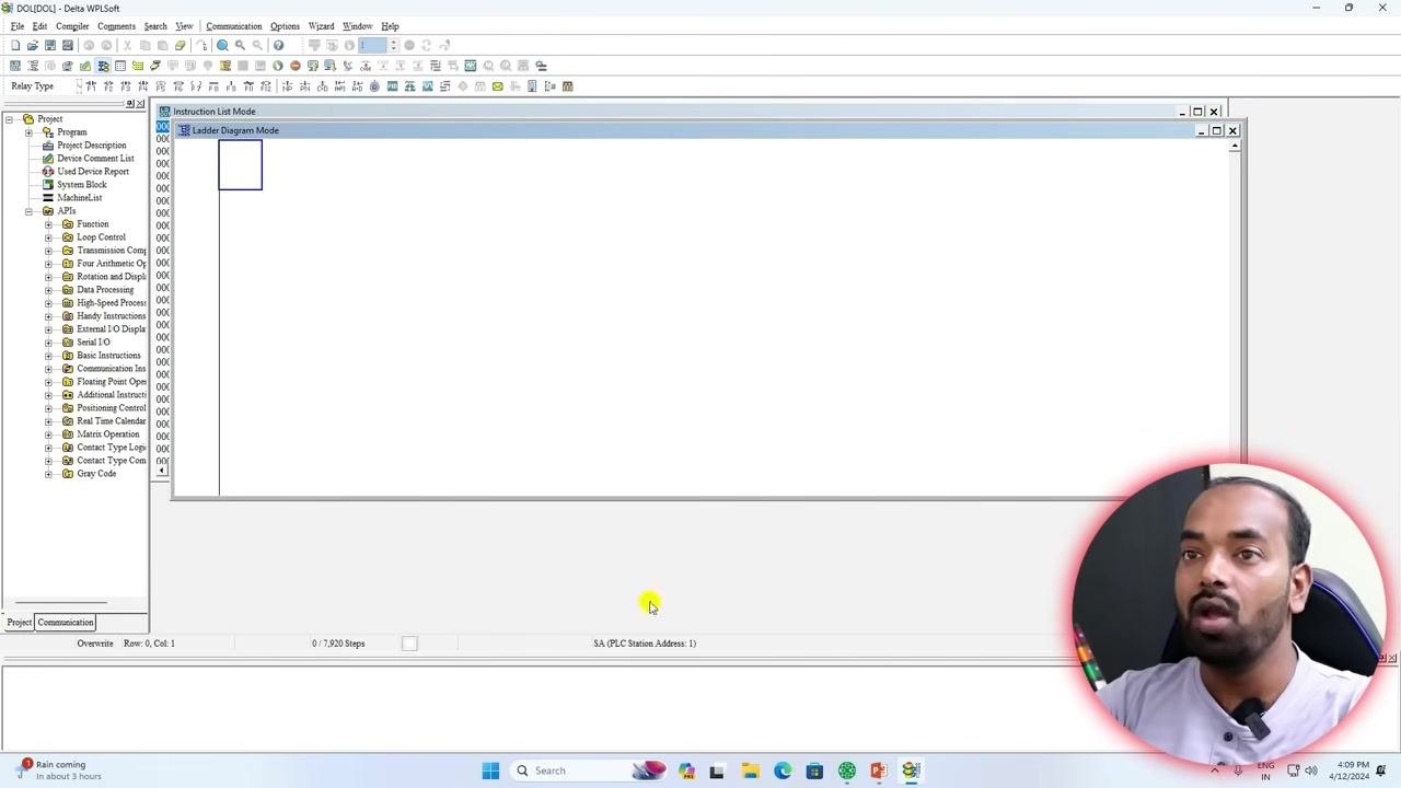
Click OK to confirm your selections and close the dialog box. The main workspace now displays the ladder diagram editor in "Instruction List Mode." The left panel shows your project structure, including sections such as Program, Project Description, Device Comment List, and various APIs.
8. Insert the STOP input contact
Prepare to assign addresses for input devices. Refer to your wiring diagram to identify which terminal each push button is connected to. For example, if your STOP push button is connected to terminal X0 on the PLC, you will use address X0 in your program.
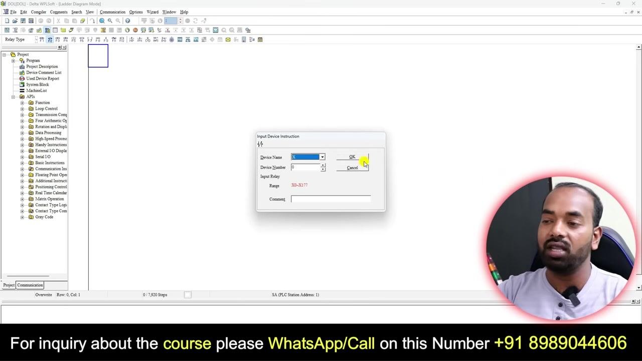
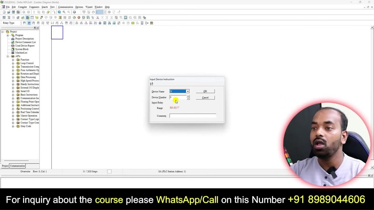
Insert a Normally Closed (NC) contact in the ladder diagram by clicking the contact symbol in the workspace. A window titled "Input Device Instruction" pops up. Configure it as follows: - Set Device Name to X (for input). - Set Device Number to the terminal number (for example, 0 for X0). - The "Input Relay" range displays as X0–X177. - In the "Comment" field, enter a description such as Stop. - Click OK to insert the contact.
Verify that the contact appears in the ladder diagram, labeled as X0 with the comment Stop next to it. This confirms that the STOP push button is correctly assigned in your program.
9. Insert the START input contact
Understand that "LD" stands for a normally open contact ("Anno Contact") in the ladder diagram editor. The workspace displays the first rung containing the STOP (X0) and START (X1) contacts, with the "Input Instruction" dialog box open and ready for the next input.
Enter the address for the START push button. In the "Input Instruction" dialog box, type ld x0 to specify the address, then press Enter to confirm.
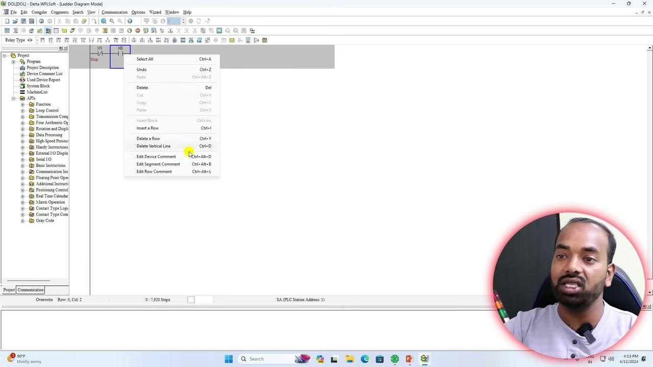
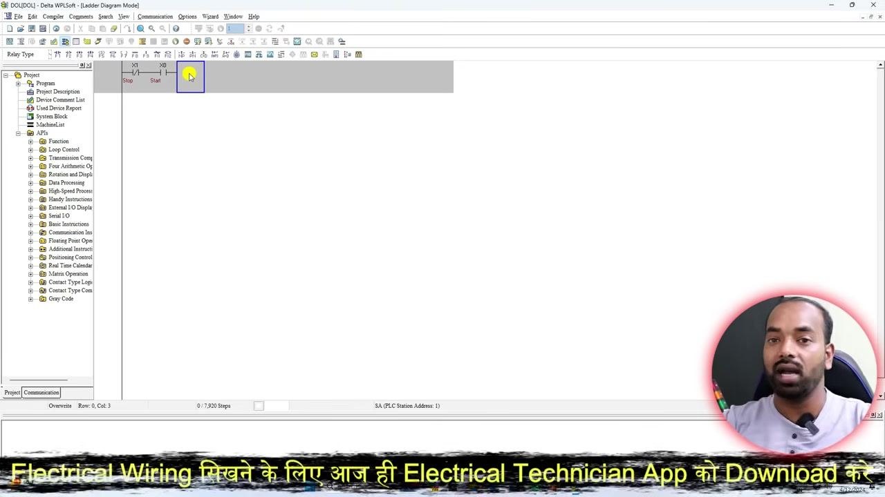
Add the START push button to the ladder diagram. The START button (X1) is now visible next to the STOP button (X0). Right-click on the workspace to open the context menu, then select Edit Device Comment (or use the shortcut Ctrl+Alt+D) to add or modify comments for the device.
10. Insert the output coil for the motor
Insert the output coil for the motor by clicking in the workspace after the START contact. The "Input Instruction" dialog box appears again. Configure it as follows: - Set Device Name to Y (for output). - Set Device Number to the appropriate output terminal (for example, 0 for Y0). - The "Output Relay" range displays as Y0–Y177. - In the "Comment" field, enter Motor. - Click OK to insert the output coil.
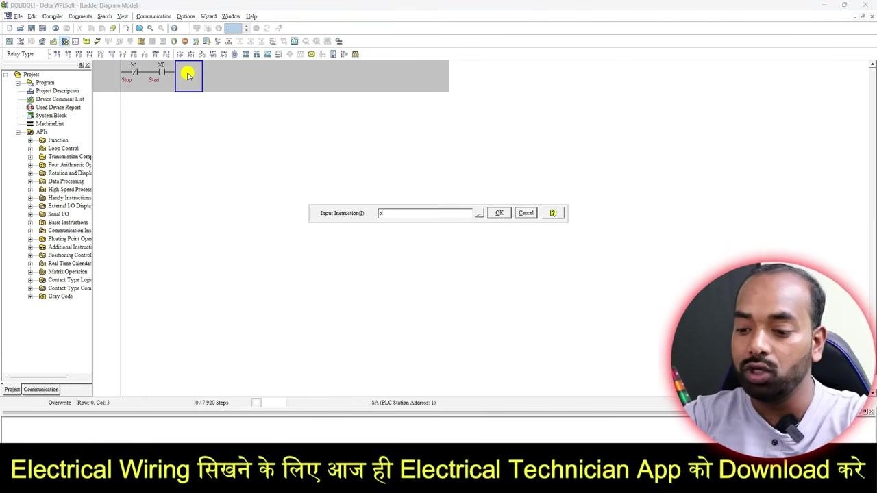
Verify the output coil in the ladder diagram. The output coil, labeled Y3 (or your selected output) with the comment Motor, appears at the end of the rung. The rung now shows the STOP (X0), START (X1), and Motor (Y3) elements connected.
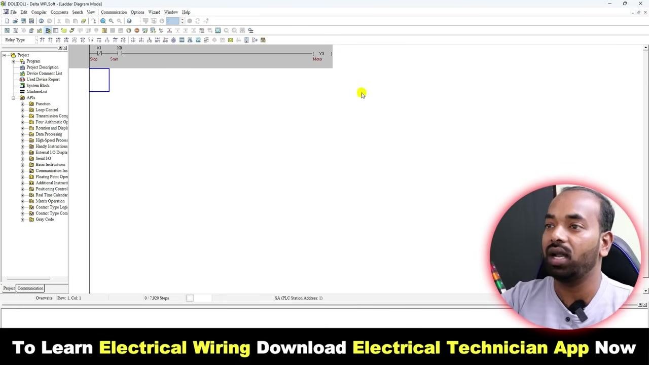
If you make a mistake or do not want a particular instruction, select the element and press Delete to remove it from the ladder diagram. You can further edit the output coil by clicking on it and updating its address or comment as required.
11. Add a holding contact (self-hold circuit)
Before proceeding, be aware that additional PLC courses and an "Electrical Wiring Master Course" are recommended as prerequisites for building foundational wiring knowledge. The Electrical Wiring Master Course is designed for electricians and electrical engineers and covers practical wiring and motor starters.
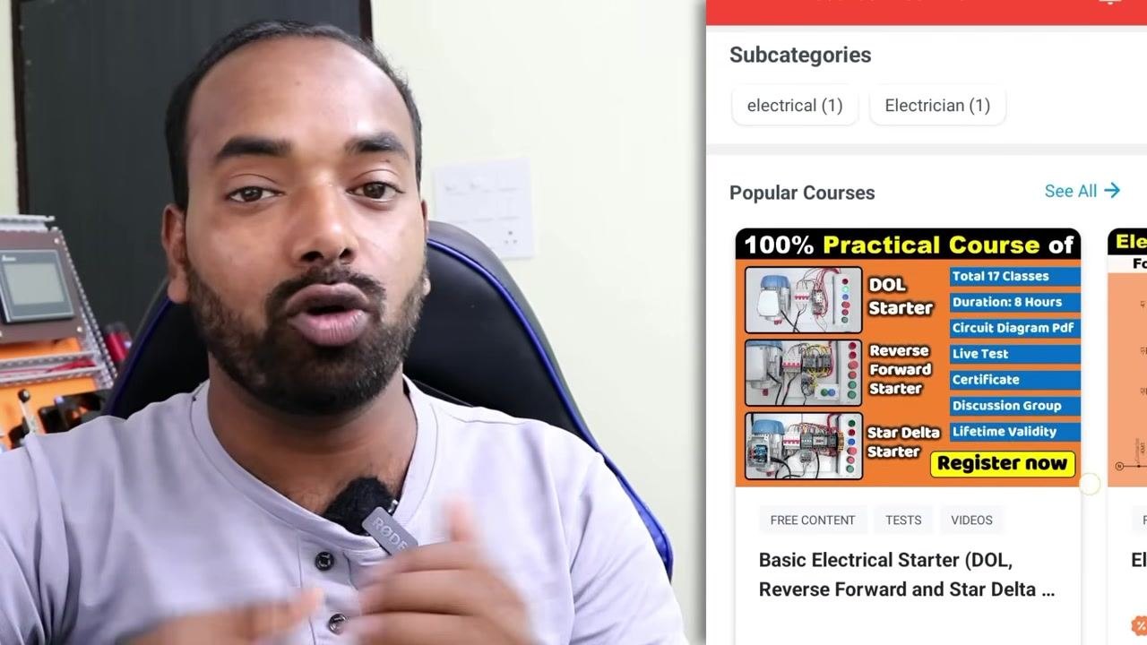
You can also install the "Electrical Technician" app from the Play Store to access additional learning materials on PLC programming and electrical wiring. The installation process is verified by Play Protect.
The app features practical courses, including DOL Starter (17 classes, 8 hours, circuit diagram PDF, live test, certificate, discussion group, lifetime validity), Reverse Forward Starter, and Star Delta Starter. You can register for these courses for hands-on experience.
Additional courses are available covering electrical wiring, motor starters, and ceiling fan winding, suitable for both beginners and professionals.
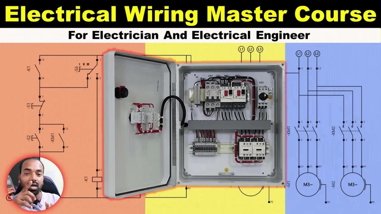
For course inquiries or enrollment, contact via WhatsApp or call +91 8989044606, as displayed at the bottom of the screen.
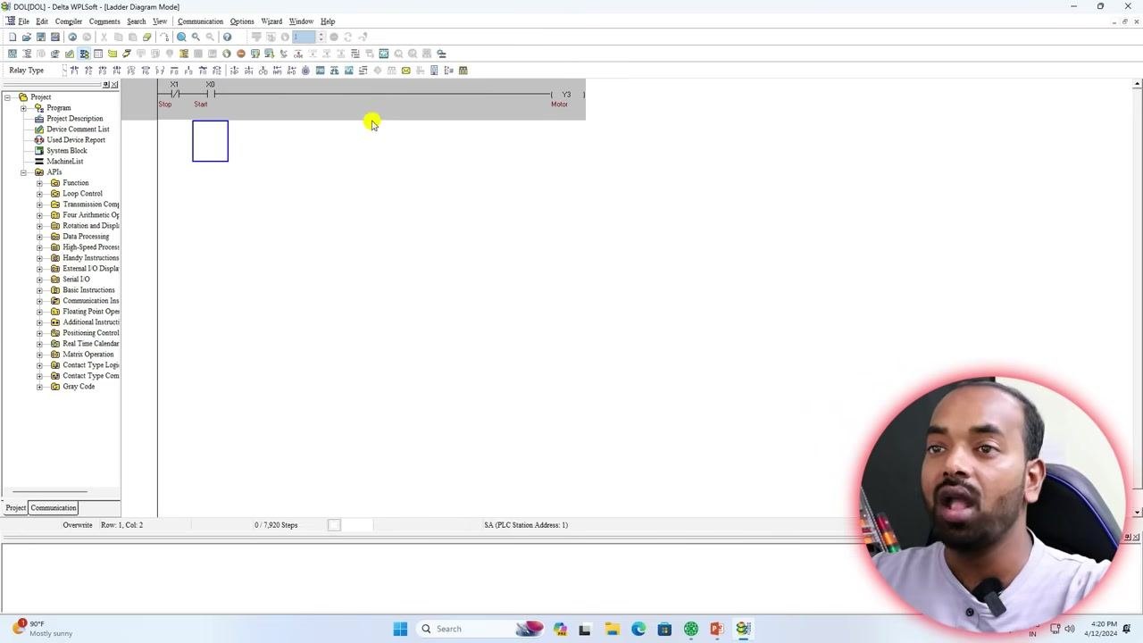
Now, prepare to add a holding circuit. In the Delta WPLSoft ladder diagram editor, ensure your rung includes STOP (X0), START (X1), and Motor (Y3) elements, and the workspace is ready for the next instruction.
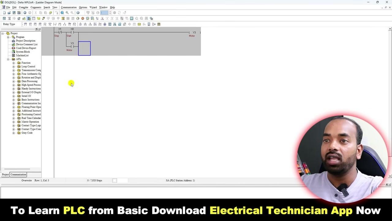
Insert the holding contact by clicking to add a new contact in parallel with the START button. The "Input Instruction" dialog box appears. Enter Y3 as the device address for the holding contact (since Y3 is the output coil for the motor), then click OK to confirm and insert it.
Verify the holding circuit. The holding contact (Y3) now appears in parallel with the START button in the ladder diagram. This ensures the motor remains energized after the START button is released, as long as the STOP button is not pressed.
12. Compile and download the program
Select the PLC device type in the device selection dialog. Choose PLC from the available options (other options may include VFD, TP, etc., but select PLC for this project). Select the PLC model number in the dropdown that matches your hardware — for example, choose the SS series model if that is your Delta hardware. Click OK to confirm your selection and open the programming window.
After confirming the PLC model, the ladder diagram editor opens, ready for programming. If needed, insert the STOP push button as a normally closed (NC) contact: click to add a new contact, select NC contact in the "Input Instruction" dialog, set the address to X1 (or the address corresponding to your STOP push button terminal), label it Stop, and click OK. Verify the STOP contact (X1) appears in the ladder diagram, labeled "Stop".
Compile the program by clicking the compile button or selecting the compile option from the menu. Wait for the software to check the program — a message such as "Compiling is complete!" appears at the bottom of the screen.
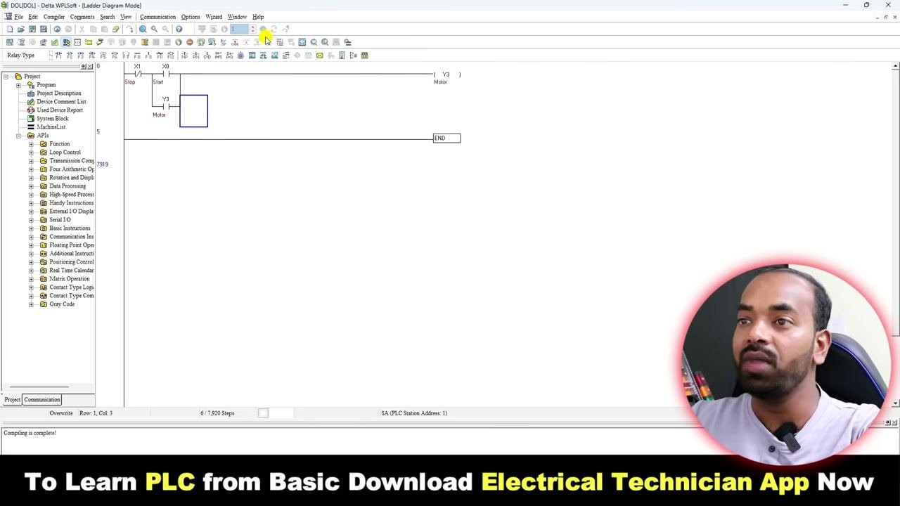
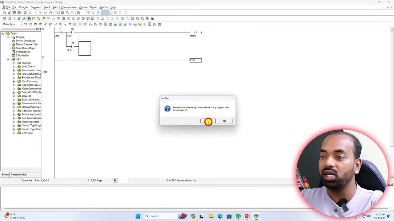
Download the program to the PLC by initiating the download process to transfer the program. A confirmation dialog appears asking, "Recover the executing status before the program was downloaded?" Click No to proceed without recovering the previous status.
13. Test the ladder logic on the PLC
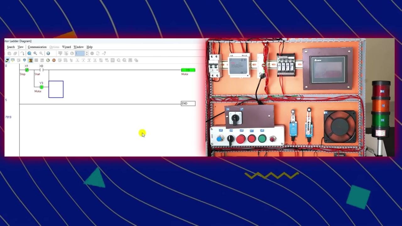
After downloading, observe the initial state by checking the status of the motor output (Y3) in the ladder diagram. The motor should be in the off condition initially.
Test the STOP and START buttons using the physical training panel. Press the START button (X0) to energize the motor (Y3); the output coil and corresponding indicator should turn green. Press the STOP button (X1) to de-energize the motor (Y3); the output coil and indicator should turn off. Observe the real-time status in both the ladder diagram and the hardware panel.
Additional learning resources
At the end of the session, review the course recommendations. A banner announces the upcoming PLC course and the prerequisite Electrical Wiring Master Course, which is compulsory before starting the PLC course and is designed for electricians and electrical engineers.
Verification and summary
By completing this procedure you have: - Reviewed the electrical panel components and their basic operation. - Wired the 24V DC power supply, push buttons, and earth connections to the PLC. - Wired the PLC output to the contactor using a 230 VAC supply. - Created a new project in WPL Editor and selected the correct PLC model. - Added STOP (X0) and START (X1) input contacts and a Motor (Y3) output coil to the ladder diagram. - Added a holding contact (Y3) in parallel with the START button to complete the self-hold (DOL starter) logic. - Compiled the program and downloaded it to the PLC. - Tested the STOP and START buttons on a physical training panel and confirmed correct motor operation in both the ladder diagram and the hardware.
What's next
Continue practicing with more advanced ladder logic and explore the recommended Electrical Wiring Master Course and PLC course for a deeper understanding of PLC how to program techniques and electrical wiring fundamentals.